ECU RENAULT DUSTER 2016 Owners Manual
[x] Cancel search | Manufacturer: RENAULT, Model Year: 2016, Model line: DUSTER, Model: RENAULT DUSTER 2016Pages: 256, PDF Size: 6.49 MB
Page 11 of 256
1.5
LOCKING AND UNLOCKING THE DOORS (1/2)
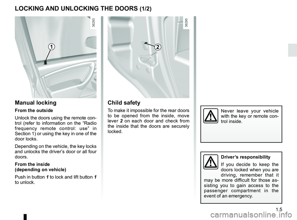
Manual locking
From the outside
Unlock the doors using the remote con-
trol (refer to information on the “Radio
frequency remote control: use” in
Section 1) or using the key in one of the
door locks.
Depending on the vehicle, the key locks
and unlocks the driver’s door or all four
doors.
From the inside
(depending on vehicle)
Push in button 1 to lock and lift button 1
to unlock.
Child safety
To make it impossible for the rear doors
to be opened from the inside, move
lever 2 on each door and check from
the inside that the doors are securely
locked.
12
Never leave your vehicle
with the key or remote con-
trol inside.
Driver’s responsibility
If you decide to keep the
doors locked when you are
driving, remember that it
may be more difficult for those as-
sisting you to gain access to the
passenger compartment in the
event of an emergency.
Page 23 of 256
1.17
METHODS OF RESTRAINT IN ADDITION TO THE FRONT SEAT BELTS (1/3)
– Have the entire restraint
system checked following
an accident.
– No operation whatsoever
is permitted on any part of the
system (air bags, electronic con-
trol units, wiring) and the system
components must not be reused
on any other vehicle, even if iden-
tical.
– To avoid premature triggering of the system which may cause
injury, only qualified Network per-
sonnel are authorisedto work on
the methods of restraint in addi-
tion to the front seat belt.
– The electric trigger system may only be tested by a specially
trained technician using special
equipment.
– When the vehicle is scrapped, contact an approved dealer for
disposal of the pretensioner and
airbag gas generators.
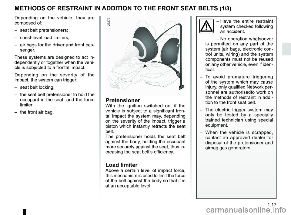
PretensionerWith the ignition switched on, if the
vehicle is subject to a significant fron-
tal impact the system may, depending
on the severity of the impact, trigger a
piston which instantly retracts the seat
belt.
The pretensioner holds the seat belt
against the body, holding the occupant
more securely against the seat, thus in-
creasing the seat belt’s efficiency.
Load limiterAbove a certain level of impact force,
this mechanism is used to limit the force
of the belt against the body so that it is
at an acceptable level.
Depending on the vehicle, they are
composed of:
– seat belt pretensioners;
– chest-level load limiters;
– air bags for the driver and front pas-
senger.
These systems are designed to act in-
dependently or together when the vehi-
cle is subjected to a frontal impact.
Depending on the severity of the
impact, the system can trigger:
– seat belt locking;
– the seat belt pretensioner to hold the occupant in the seat, and the force
limiter;
– the front air bag.
Page 93 of 256
2.17
DRIVING ADVICE, ECO-DRIVING (3/5)
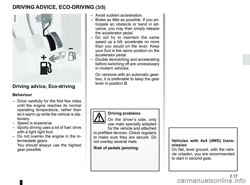
– Avoid sudden acceleration.
– Brake as little as possible. If you an-ticipate an obstacle or bend in ad-
vance, you may then simply release
the accelerator pedal.
– Do not try to maintain the same speed up a hill, accelerate no more
than you would on the level. Keep
your foot in the same position on the
accelerator pedal.
– Double declutching and accelerating before switching off are unnecessary
in modern vehicles.
On versions with an automatic gear-
box, it is preferable to keep the gear
lever in position D.
Vehicles with 4x4 (4WD) trans-
mission
On flat, level ground, with the vehi-
cle unladen, you are recommended
to start in second gear.
Driving advice, Eco-driving
Behaviour
– Drive carefully for the first few miles
until the engine reaches its normal
operating temperature, rather than
let it warm up while the vehicle is sta-
tionary.
– Speed is expensive.
– Sporty driving uses a lot of fuel: drive with a light right foot.
– Do not overrev the engine in the in- termediate gears.
You should always use the highest gear possible.
Driving problems
On the driver’s side, only
use mats specially adapted
for the vehicle and attached
to prefitted devices. Check regularly
to make sure they are secure. Do
not overlay several mats.
Risk of pedals jamming .
Page 143 of 256
3.15
REAR HEADRESTS
The headrest is a safety
component. Ensure that it is
fitted and in the correct po-
sition: the top of your head
should be in line with the top of the
headrest.
C
1
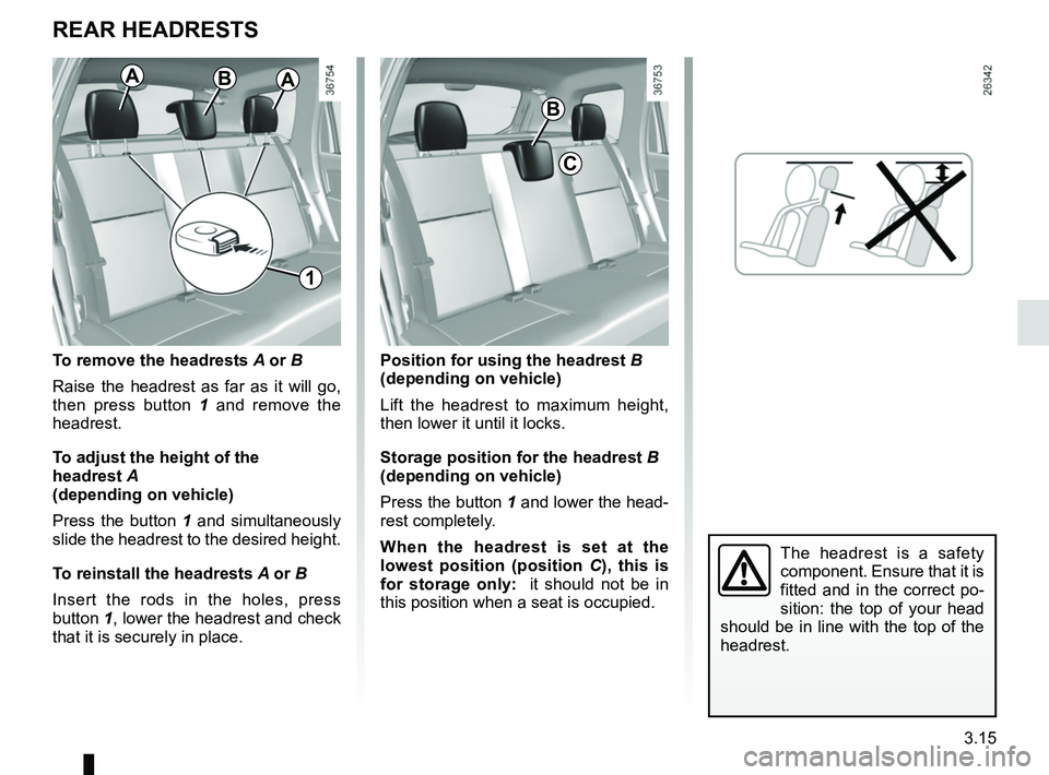
To remove the headrests A or B
Raise the headrest as far as it will go,
then press button 1 and remove the
headrest.
To adjust the height of the
headrest A
(depending on vehicle)
Press the button 1 and simultaneously
slide the headrest to the desired height.
To reinstall the headrests A or B
Insert the rods in the holes, press
button 1, lower the headrest and check
that it is securely in place. Position for using the headrest
B
(depending on vehicle)
Lift the headrest to maximum height,
then lower it until it locks.
Storage position for the headrest B
(depending on vehicle)
Press the button 1 and lower the head-
rest completely.
When the headrest is set at the
lowest position (position C ), this is
for storage only: it should not be in
this position when a seat is occupied.
BAA
B
Page 164 of 256
4.6
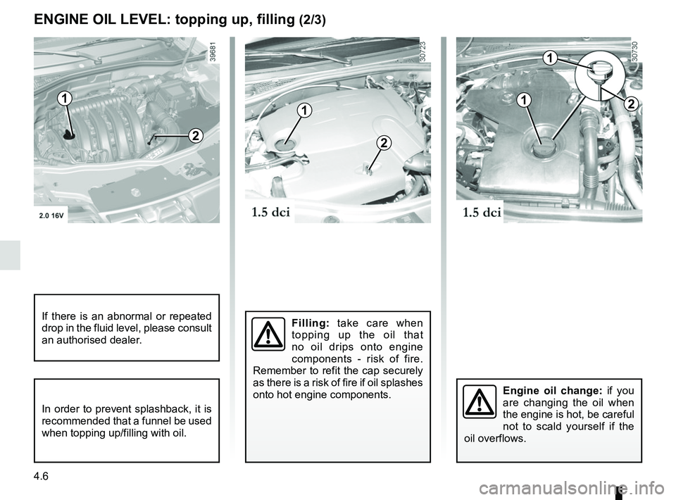
ENGINE OIL LEVEL: topping up, filling (2/3)
Filling: take care when
topping up the oil that
no oil drips onto engine
components - risk of fire.
Remember to refit the cap securely
as there is a risk of fire if oil splashes
onto hot engine components.If there is an abnormal or repeated
drop in the fluid level, please consult
an authorised dealer.
Engine oil change: if you
are changing the oil when
the engine is hot, be careful
not to scald yourself if the
oil overflows.
1
2
1
1
2
In order to prevent splashback, it is
recommended that a funnel be used
when topping up/filling with oil.
1
2
Page 175 of 256
4.17
Respect local regulations about wash-
ing vehicles (e.g. do not wash your ve-
hicle on a public highway).
Observe the vehicle stopping distances
when driving on gravelled surfaces to
prevent paint damage.
Repair, or have repaired quickly, areas
where the paint has been damaged, to
prevent corrosion spreading.
Remember to visit the body shop pe-
riodically in order to maintain your
anti-corrosion warranty. Refer to the
Maintenance Document.
If it is necessary to clean mechani-
cal components, hinges, etc., spray
them with products approved by our
Technical Department to protect them
after they have been cleaned.
BODYWORK MAINTENANCE (2/2)
We have selected special products
to care for your vehicle and you can
obtain these from the manufactur-
er’s accessory outlets.
Using a roller type car wash
Return the windscreen wiper stalk to
the Park position (refer to the informa-
tion on the “Windscreen washer, wiper”
in Section 1). Check the mounting of
external accessories, additional lights
and mirrors, and ensure that the wiper
blades are secured with adhesive tape.
Remove the radio aerial mast if your
vehicle is fitted with this equipment.
Remember to remove the tape and refit
the antenna after washing.
Cleaning the headlights
As the headlights are made of plastic
“glass”, use a soft cloth or cotton wool
to clean them. If this does not clean
them properly, moisten the cloth with
soapy water, then wipe clean with a soft
damp cloth or cotton wool.
Finally, carefully dry off with a soft dry
cloth.
Cleaning products containing alco-
hol must not be used.
Vehicles with a matte paint
finish
This type of paint requires certain pre-
cautions.
Do not do the following
– use wax-based products (polishing);
– rub hard;
– wash the vehicle in a roller-type car
wash;
– wash the vehicle using a high-pres-
sure device;
– attach stickers to the paintwork (risk
of leaving marks).
You should do the following
Wash the vehicle by hand using plenty
of water, using a soft cloth or a gentle
sponge.
Page 180 of 256
5.2
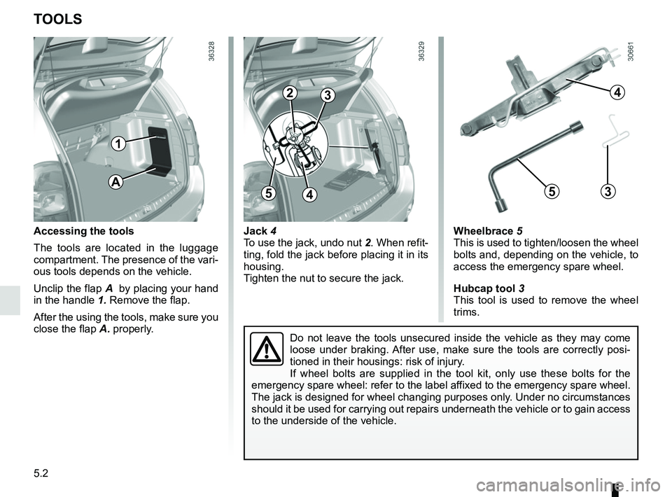
Jack 4
To use the jack, undo nut 2. When refit-
ting, fold the jack before placing it in its
housing.
Tighten the nut to secure the jack.
TOOLS
Accessing the tools
The tools are located in the luggage
compartment. The presence of the vari-
ous tools depends on the vehicle.
Unclip the flap A by placing your hand
in the handle 1. Remove the flap.
After the using the tools, make sure you
close the flap A. properly. Wheelbrace 5
This is used to tighten/loosen the wheel
bolts and, depending on the vehicle, to
access the emergency spare wheel.
Hubcap tool
3
This tool is used to remove the wheel
trims.
4
35
Do not leave the tools unsecured inside the vehicle as they may come
loose under braking. After use, make sure the tools are correctly posi-
tioned in their housings: risk of injury.
If wheel bolts are supplied in the tool kit, only use these bolts for th\
e
emergency spare wheel: refer to the label affixed to the emergency spare wheel.
The jack is designed for wheel changing purposes only. Under no circumstances
should it be used for carrying out repairs underneath the vehicle or to \
gain access
to the underside of the vehicle.
23
45A
1
Page 186 of 256
5.8
TYRE INFLATION KIT (4/4)
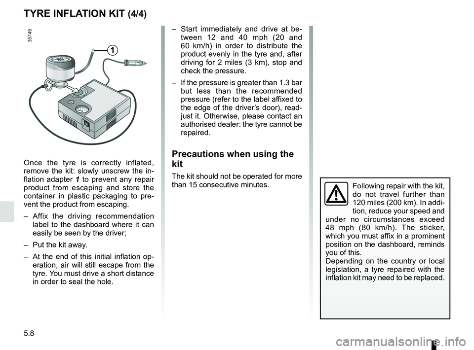
Once the tyre is correctly inflated,
remove the kit: slowly unscrew the in-
flation adapter 1 to prevent any repair
product from escaping and store the
container in plastic packaging to pre-
vent the product from escaping.
– Affix the driving recommendation label to the dashboard where it can
easily be seen by the driver;
– Put the kit away.
– At the end of this initial inflation op- eration, air will still escape from the
tyre. You must drive a short distance
in order to seal the hole.
– Start immediately and drive at be-tween 12 and 40 mph (20 and
60 km/h) in order to distribute the
product evenly in the tyre and, after
driving for 2 miles (3 km), stop and
check the pressure.
– If the pressure is greater than 1.3 bar but less than the recommended
pressure (refer to the label affixed to
the edge of the driver’s door), read-
just it. Otherwise, please contact an
authorised dealer: the tyre cannot be
repaired.
Precautions when using the
kit
The kit should not be operated for more
than 15 consecutive minutes.
1
Following repair with the kit,
do not travel further than
120 miles (200 km). In addi-
tion, reduce your speed and
under no circumstances exceed
48 mph (80 km/h). The sticker,
which you must affix in a prominent
position on the dashboard, reminds
you of this.
Depending on the country or local
legislation, a tyre repaired with the
inflation kit may need to be replaced.
Page 209 of 256
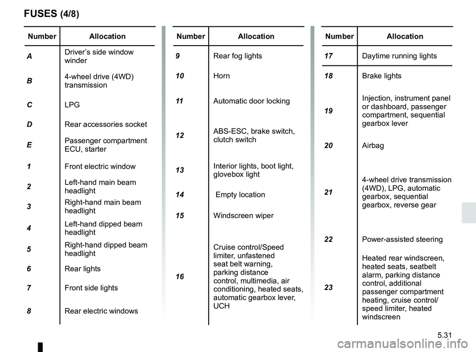
5.31
Number Allocation
A Driver’s side window
winder
B 4-wheel drive (4WD)
transmission
C LPG
D Rear accessories socket
E Passenger compartment
ECU, starter
1 Front electric window
2 Left-hand main beam
headlight
3 Right-hand main beam
headlight
4 Left-hand dipped beam
headlight
5 Right-hand dipped beam
headlight
6 Rear lights
7 Front side lights
8 Rear electric windowsNumber Allocation
9 Rear fog lights
10 Horn
11 Automatic door locking
12 ABS-ESC, brake switch,
clutch switch
13 Interior lights, boot light,
glovebox light
14 Empty location
15 Windscreen wiper
16 Cruise control/Speed
limiter, unfastened
seat belt warning,
parking distance
control, multimedia, air
conditioning, heated seats,
automatic gearbox lever,
UCHNumber Allocation
17 Daytime running lights
18 Brake lights
19 Injection, instrument panel
or dashboard, passenger
compartment, sequential
gearbox lever
20 Airbag
21 4-wheel drive transmission
(4WD), LPG, automatic
gearbox, sequential
gearbox, reverse gear
22 Power-assisted steering
23 Heated rear windscreen,
heated seats, seatbelt
alarm, parking distance
control, additional
passenger compartment
heating, cruise control/
speed limiter, heated
windscreen
FUSES (4/8)
Page 210 of 256
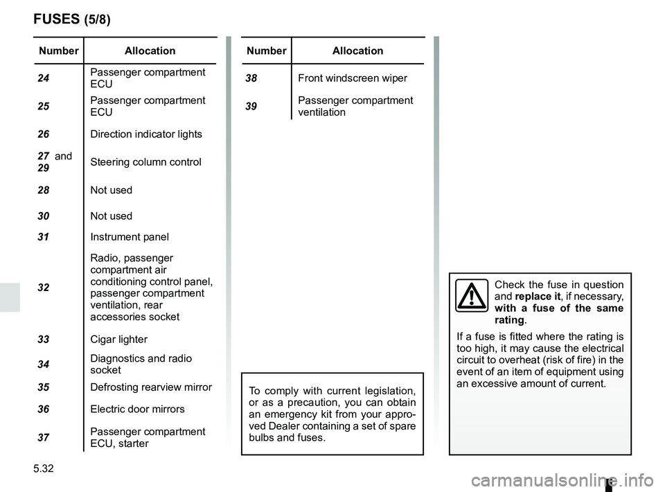
5.32
FUSES (5/8)
Number Allocation
24 Passenger compartment
ECU
25 Passenger compartment
ECU
26 Direction indicator lights
27 and
29 Steering column control
28 Not used
30 Not used
31 Instrument panel
32 Radio, passenger
compartment air
conditioning control panel,
passenger compartment
ventilation, rear
accessories socket
33 Cigar lighter
34 Diagnostics and radio
socket
35 Defrosting rearview mirror
36 Electric door mirrors
37 Passenger compartment
ECU, starterNumber Allocation
38 Front windscreen wiper
39 Passenger compartment
ventilation
Check the fuse in question
and
replace it, if necessary,
with a fuse of the same
rating.
If a fuse is fitted where the rating is
too high, it may cause the electrical
circuit to overheat (risk of fire) in the
event of an item of equipment using
an excessive amount of current.
To comply with current legislation,
or as a precaution, you can obtain
an emergency kit from your appro-
ved Dealer containing a set of spare
bulbs and fuses.