coolant temperature RENAULT ESPACE 2000 J66 / 3.G Technical Note 3426A Workshop Manual
[x] Cancel search | Manufacturer: RENAULT, Model Year: 2000, Model line: ESPACE, Model: RENAULT ESPACE 2000 J66 / 3.GPages: 52, PDF Size: 0.98 MB
Page 38 of 52

Downloaded from www.Manualslib.com manuals search engine COOLING SYSTEM
Diagram
19
19-2
Diagram
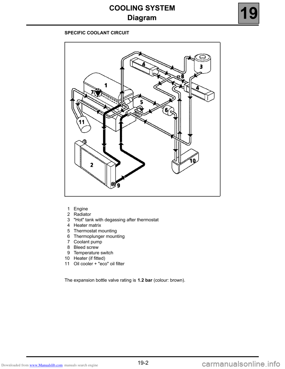
SPECIFIC COOLANT CIRCUIT
1Engine
2Radiator
3"Hot" tank with degassing after thermostat
4Heater matrix
5Thermostat mounting
6Thermoplunger mounting
7Coolant pump
8Bleed screw
9Temperature switch
10 Heater (if fitted)
11 Oil cooler + "eco" oil filter
The expansion bottle valve rating is 1.2 bar (colour: brown).
Page 46 of 52

Downloaded from www.Manualslib.com manuals search engine HEATING
Additional heating
61
161HEATING
Additional heating
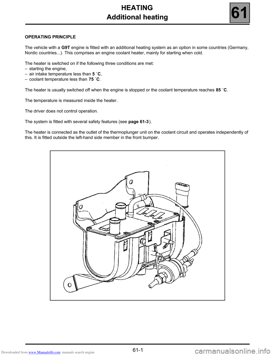
OPERATING PRINCIPLE
The vehicle with a G9T engine is fitted with an additional heating system as an option in some countries (Germany,
Nordic countries...). This comprises an engine coolant heater, mainly for starting when cold.
The heater is switched on if the following three conditions are met:
–starting the engine,
–air intake temperature less than 5 ˚C,
–coolant temperature less than 75 ˚C.
The heater is usually switched off when the engine is stopped or the coolant temperature reaches 85 ˚C.
The temperature is measured inside the heater.
The driver does not control operation.
The system is fitted with several safety features (see page 61-3).
The heater is connected as the outlet of the thermoplunger unit on the coolant circuit and operates independently of
this. It is fitted outside the left-hand side member in the front bumper.
61-1
Page 47 of 52

Downloaded from www.Manualslib.com manuals search engine HEATING
Additional heating
61
61-2
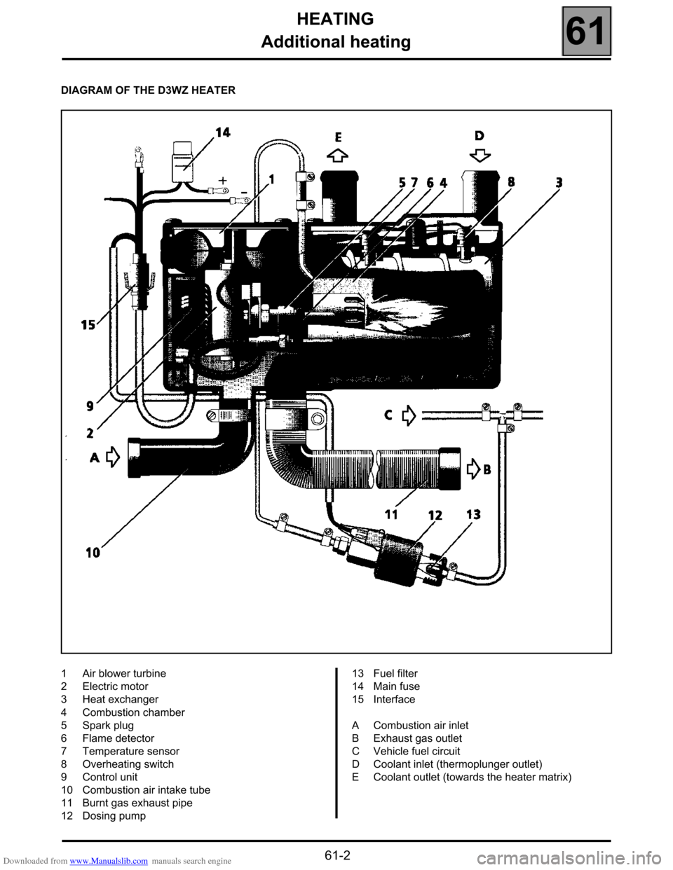
DIAGRAM OF THE D3WZ HEATER
1Air blower turbine
2Electric motor
3Heat exchanger
4Combustion chamber
5Spark plug
6Flame detector
7Temperature sensor
8Overheating switch
9Control unit
10 Combustion air intake tube
11 Burnt gas exhaust pipe
12 Dosing pump 13 Fuel filter
14 Main fuse
15 Interface
ACombustion air inlet
BExhaust gas outlet
CVehicle fuel circuit
DCoolant inlet (thermoplunger outlet)
ECoolant outlet (towards the heater matrix)
Page 48 of 52

Downloaded from www.Manualslib.com manuals search engine HEATING
Additional heating
61
61-3
TECHNICAL SPECIFICATIONS
The heater is fitted with an igniter appropriate for the
vehicle fuel.
It operates in two power levels:
–1˚) Low speed:
●Power: 1600 Watts,
●Fuel consumption: 0.2 l/hour.
–2˚) High speed:
●Power: 3300 Watts.
●Fuel consumption: 0.4 l/hour.
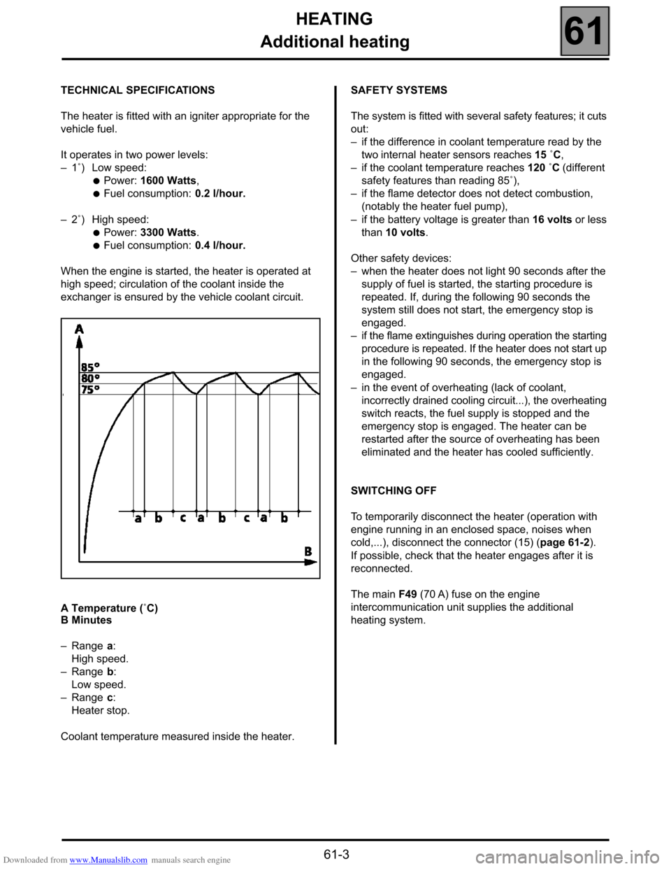
When the engine is started, the heater is operated at
high speed; circulation of the coolant inside the
exchanger is ensured by the vehicle coolant circuit.
A Temperature (˚C)
B Minutes
–Range a:
High speed.
–Range b:
Low speed.
–Range c:
Heater stop.
Coolant temperature measured inside the heater.SAFETY SYSTEMS
The system is fitted with several safety features; it cuts
out:
–if the difference in coolant temperature read by the
two internal heater sensors reaches 15 ˚C,
–if the coolant temperature reaches 120 ˚C (different
safety features than reading 85˚),
–if the flame detector does not detect combustion,
(notably the heater fuel pump),
–if the battery voltage is greater than 16 volts or less
than 10 volts.
Other safety devices:
–when the heater does not light 90 seconds after the
supply of fuel is started, the starting procedure is
repeated. If, during the following 90 seconds the
system still does not start, the emergency stop is
engaged.
–if the flame extinguishes during operation the starting
procedure is repeated. If the heater does not start up
in the following 90 seconds, the emergency stop is
engaged.
–in the event of overheating (lack of coolant,
incorrectly drained cooling circuit...), the overheating
switch reacts, the fuel supply is stopped and the
emergency stop is engaged. The heater can be
restarted after the source of overheating has been
eliminated and the heater has cooled sufficiently.
SWITCHING OFF
To temporarily disconnect the heater (operation with
engine running in an enclosed space, noises when
cold,...), disconnect the connector (15) (page 61-2).
If possible, check that the heater engages after it is
reconnected.
The main F49 (70 A) fuse on the engine
intercommunication unit supplies the additional
heating system.