cooling RENAULT ESPACE 2000 J66 / 3.G Technical Note 3426A Workshop Manual
[x] Cancel search | Manufacturer: RENAULT, Model Year: 2000, Model line: ESPACE, Model: RENAULT ESPACE 2000 J66 / 3.GPages: 52, PDF Size: 0.98 MB
Page 2 of 52
Downloaded from www.Manualslib.com manuals search engine Contents
Page
07
10
11
12
16
VALUES AND SETTINGS
Capacities - Grades 07-1
Tightening the cylinder head 07-2
ENGINE AND PERIPHERALS
Identification 10-1
Oil pressure 10-2
Engine and transmission assembly 10-3
TOP AND FRONT OF ENGINE
Accessories belt 11-1
Timing belt 11-2
Cylinder head gasket 11-8
TURBOCHARGING - FUEL
MIXTURE
Turbocharger 12-1
Air inlet 12-3
Exhaust manifold 12-7
Inlet manifold 12-8
STARTING - CHARGING
Alternator 16-1
Starter 16-4Page
19
21
61
62
COOLING SYSTEM
Filling - bleeding 19-1
Diagram 19-2
Coolant pump 19-3
Suspended mountings 19-4
Cooling system 19-5
MANUAL GEARBOX
Identification 21-1
Gears 21-2
Lubricants 21-3
Remove and refit 21-4
HEATING
Additional heating 61-1
AIR CONDITIONING
Air conditioning compressor 62-1
Page 8 of 52
Downloaded from www.Manualslib.com manuals search engine ENGINE AND PERIPHERALS
Engine and transmission assembly
10
10-4
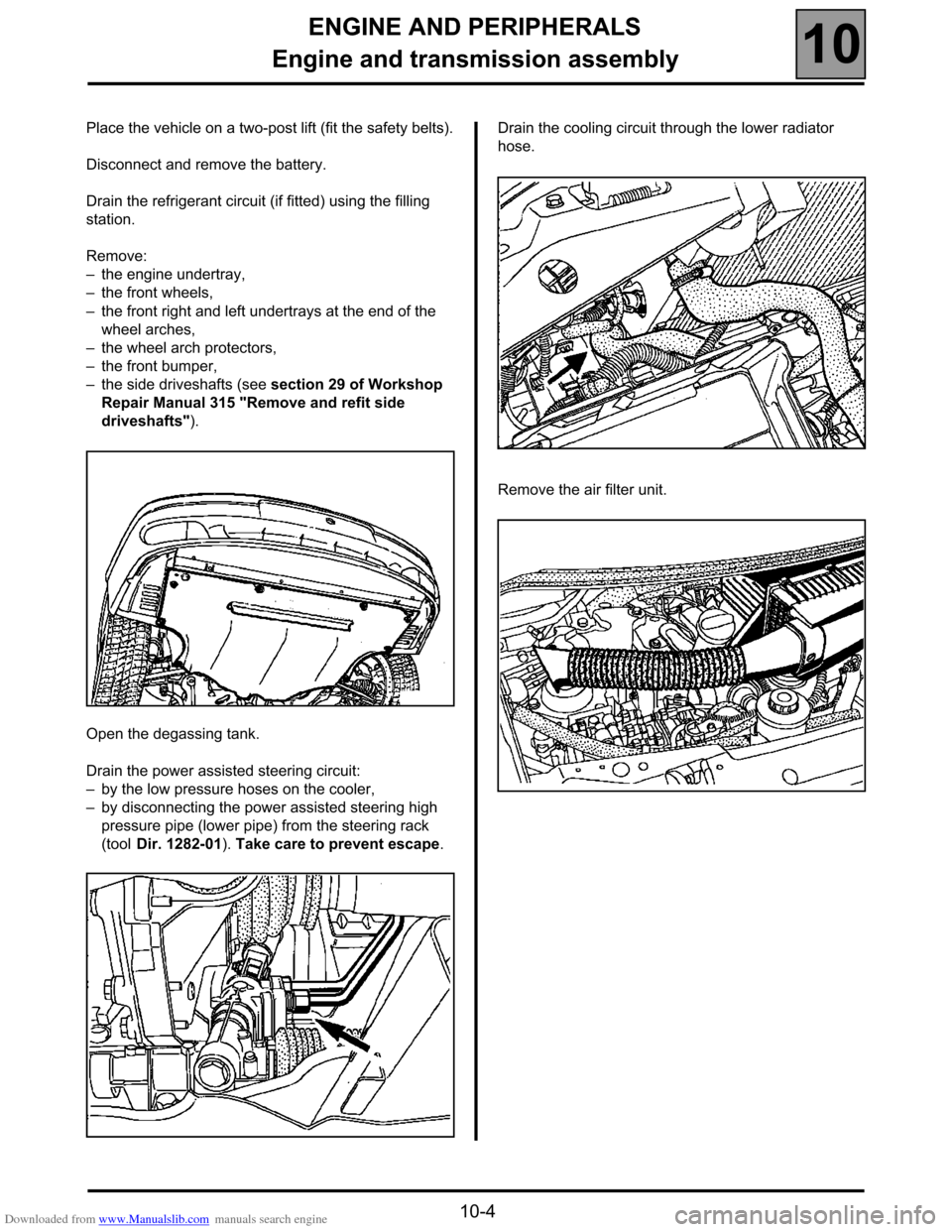
Place the vehicle on a two-post lift (fit the safety belts).
Disconnect and remove the battery.
Drain the refrigerant circuit (if fitted) using the filling
station.
Remove:
–the engine undertray,
–the front wheels,
–the front right and left undertrays at the end of the
wheel arches,
–the wheel arch protectors,
–the front bumper,
–the side driveshafts (see section 29 of Workshop
Repair Manual 315 "Remove and refit side
driveshafts").
Open the degassing tank.
Drain the power assisted steering circuit:
–by the low pressure hoses on the cooler,
–by disconnecting the power assisted steering high
pressure pipe (lower pipe) from the steering rack
(tool Dir. 1282-01). Take care to prevent escape.Drain the cooling circuit through the lower radiator
hose.
Remove the air filter unit.
Page 13 of 52
Downloaded from www.Manualslib.com manuals search engine ENGINE AND PERIPHERALS
Engine and transmission assembly
10
10-9
REFITTING - Special points
Pre-position the gearbox control cables.
Position the engine/gearbox assembly in its
compartment. Check the rear of the gearbox in relation
to the sub-frame.
Fitting suspended mountings: see section 19
"Suspended mountings".
Tighten all the bolts, nuts and studs to the
recommended torques.
Refitting is the reverse of removal.
Press the brake pedal several times to bring the
pistons into contact with the brake pads.
Reprogram all the components deprogrammed by
disconnecting the battery.
Fill the refrigerant circuit using the filling station (see
section 62 "Air conditioning").
Refrigerant fluid R134a: 800 ± 20 g.
Carry out:
–filling and bleeding of the cooling circuit (see
section 19),
–filling and bleeding of the power assisted steering
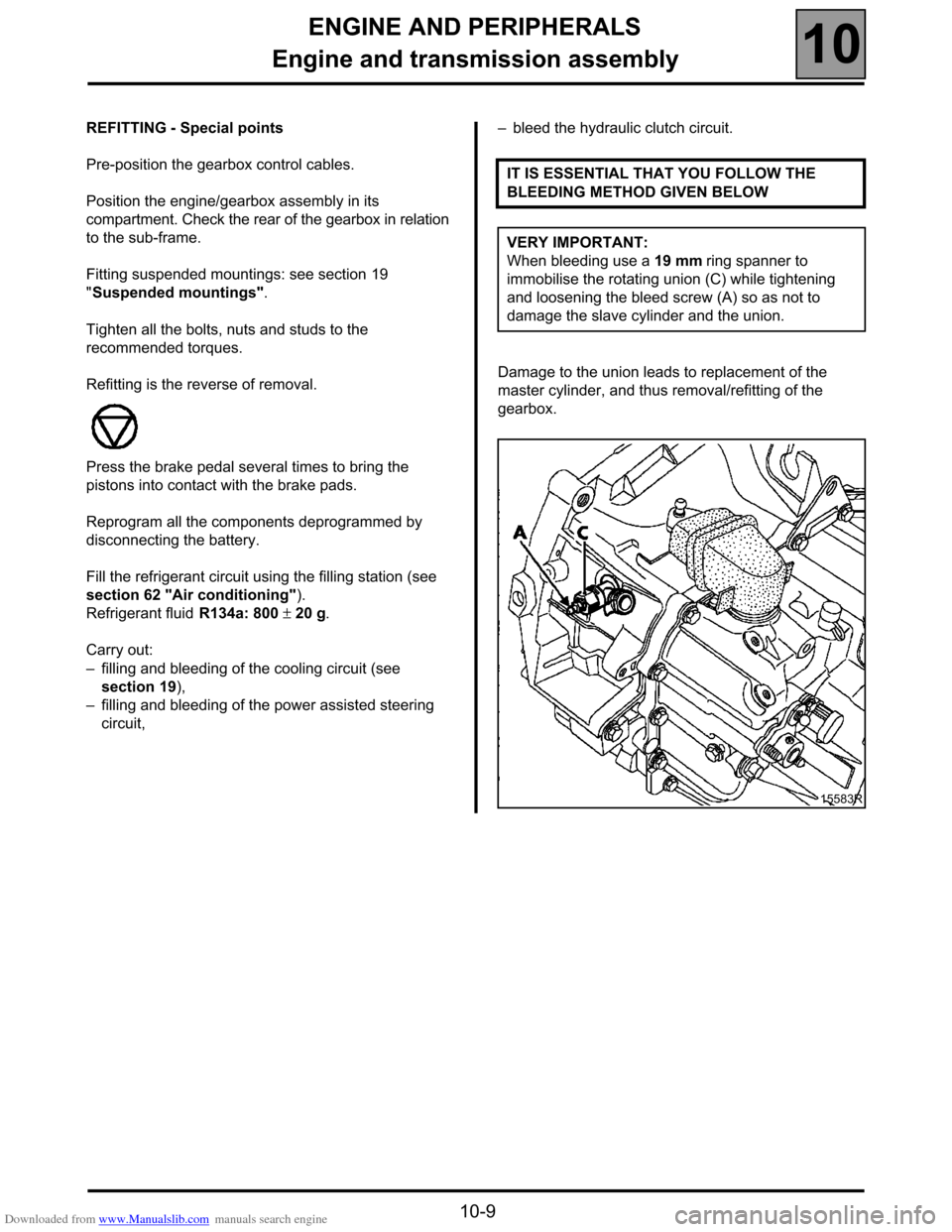
circuit,–bleed the hydraulic clutch circuit.
Damage to the union leads to replacement of the
master cylinder, and thus removal/refitting of the
gearbox.IT IS ESSENTIAL THAT YOU FOLLOW THE
BLEEDING METHOD GIVEN BELOW
VERY IMPORTANT:
When bleeding use a 19 mm ring spanner to
immobilise the rotating union (C) while tightening
and loosening the bleed screw (A) so as not to
damage the slave cylinder and the union.
15583R
Page 37 of 52

Downloaded from www.Manualslib.com manuals search engine COOLING SYSTEM
Filling and bleeding
19
119COOLING SYSTEM
Filling and bleeding
There is continuous circulation in the heater matrices.
FILLING
It is essential to open the two bleed screws at the
top of the radiator and the cylinder head coolant
pipe housing outlet.
Fill the circuit through the expansion bottle opening.
Close the bleed screws as soon as the liquid starts to
flow in a continuous stream.
Start the engine (2 500 rpm).
Adjust the level by overflow for a period of about
4 minutes.
Close the bottle.
BLEEDING
Allow the engine to run for about 20 minutes at
2 500 rpm, until the engine fans(s) operate (time
necessary for automatic degassing).
Check the liquid level is at the "Maximum" marker.
DO NOT OPEN THE BLEED SCREWS WHILST THE
ENGINE IS RUNNING.
REFIT THE EXPANSION BOTTLE CAP WHILE THE
ENGINE IS WARM.
19-1
Page 38 of 52
Downloaded from www.Manualslib.com manuals search engine COOLING SYSTEM
Diagram
19
19-2
Diagram
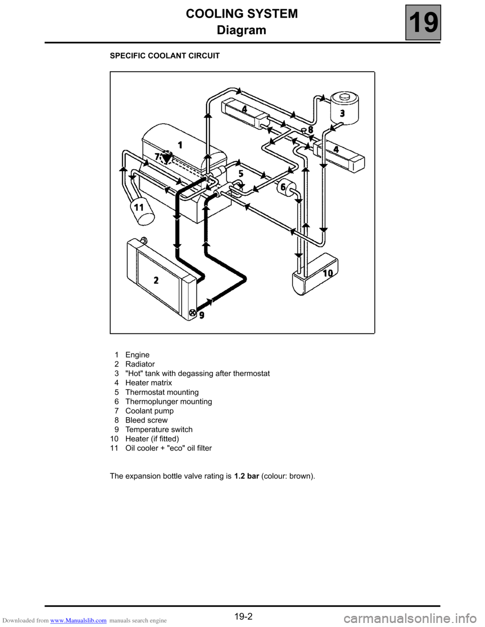
SPECIFIC COOLANT CIRCUIT
1Engine
2Radiator
3"Hot" tank with degassing after thermostat
4Heater matrix
5Thermostat mounting
6Thermoplunger mounting
7Coolant pump
8Bleed screw
9Temperature switch
10 Heater (if fitted)
11 Oil cooler + "eco" oil filter
The expansion bottle valve rating is 1.2 bar (colour: brown).
Page 39 of 52
Downloaded from www.Manualslib.com manuals search engine COOLING SYSTEM
Coolant pump
19
19-3
Coolant pump
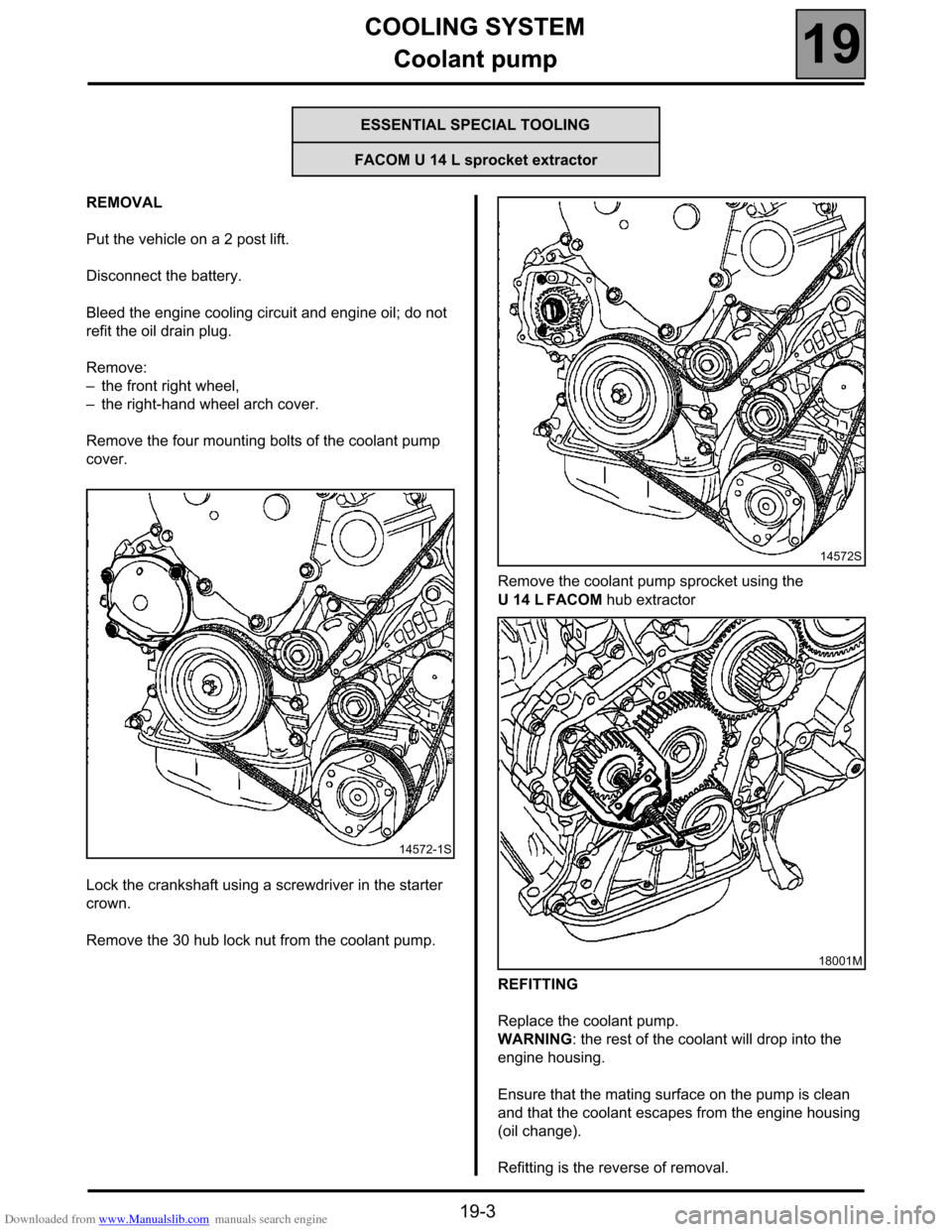
REMOVAL
Put the vehicle on a 2 post lift.
Disconnect the battery.
Bleed the engine cooling circuit and engine oil; do not
refit the oil drain plug.
Remove:
–the front right wheel,
–the right-hand wheel arch cover.
Remove the four mounting bolts of the coolant pump
cover.
Lock the crankshaft using a screwdriver in the starter
crown.
Remove the 30 hub lock nut from the coolant pump.Remove the coolant pump sprocket using the
U 14 L FACOM hub extractor
REFITTING
Replace the coolant pump.
WARNING: the rest of the coolant will drop into the
engine housing.
Ensure that the mating surface on the pump is clean
and that the coolant escapes from the engine housing
(oil change).
Refitting is the reverse of removal.
ESSENTIAL SPECIAL TOOLING
FACOM U 14 L sprocket extractor
14572-1S
14572S
18001M
Page 40 of 52
Downloaded from www.Manualslib.com manuals search engine COOLING SYSTEM
Suspended mountings
19
19-4
Suspended mountings
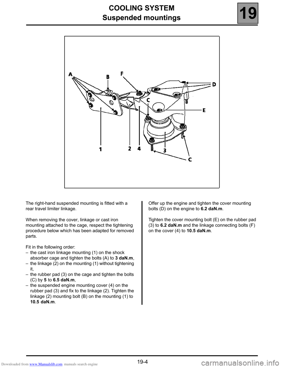
The right-hand suspended mounting is fitted with a
rear travel limiter linkage.
When removing the cover, linkage or cast iron
mounting attached to the cage, respect the tightening
procedure below which has been adapted for removed
parts.
Fit in the following order:
–the cast iron linkage mounting (1) on the shock
absorber cage and tighten the bolts (A) to 3 daN.m,
–the linkage (2) on the mounting (1) without tightening
it,
–the rubber pad (3) on the cage and tighten the bolts
(C) by 5 to 6.5 daN.m,
–the suspended engine mounting cover (4) on the
rubber pad (3) and fix to the linkage (2). Tighten the
linkage (2) mounting bolt (B) on the mounting (1) to
10.5 daN.m.Offer up the engine and tighten the cover mounting
bolts (D) on the engine to 6.2 daN.m.
Tighten the cover mounting bolt (E) on the rubber pad
(3) to 6.2 daN.m and the linkage connecting bolts (F)
on the cover (4) to 10.5 daN.m.
Page 41 of 52
Downloaded from www.Manualslib.com manuals search engine COOLING SYSTEM
Cooling system
19
19-5
COOLING SYSTEM
Cooling system
Bleed the cooling circuit, the air conditioning circuit
(see special manual for air conditioning)
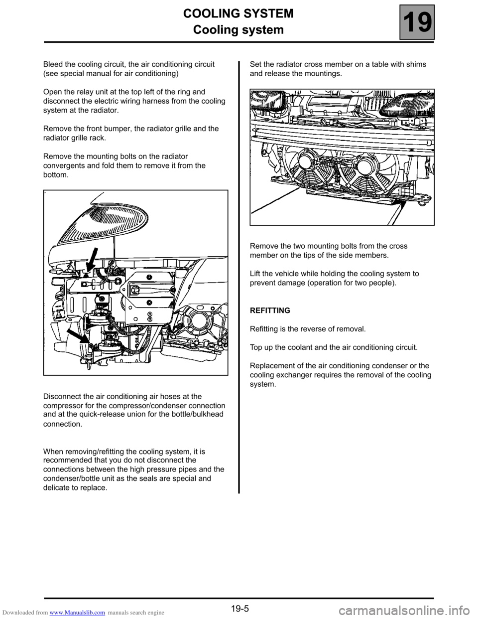
Open the relay unit at the top left of the ring and
disconnect the electric wiring harness from the cooling
system at the radiator.
Remove the front bumper, the radiator grille and the
radiator grille rack.
Remove the mounting bolts on the radiator
convergents and fold them to remove it from the
bottom.
Disconnect the air conditioning air hoses at the
compressor for the compressor/condenser connection
and at the quick-release union for the bottle/bulkhead
connection.
When removing/refitting the cooling system, it is
recommended that you do not disconnect the
connections between the high pressure pipes and the
condenser/bottle unit as the seals are special and
delicate to replace.Set the radiator cross member on a table with shims
and release the mountings.
Remove the two mounting bolts from the cross
member on the tips of the side members.
Lift the vehicle while holding the cooling system to
prevent damage (operation for two people).
REFITTING
Refitting is the reverse of removal.
Top up the coolant and the air conditioning circuit.
Replacement of the air conditioning condenser or the
cooling exchanger requires the removal of the cooling
system.
Page 48 of 52
Downloaded from www.Manualslib.com manuals search engine HEATING
Additional heating
61
61-3
TECHNICAL SPECIFICATIONS
The heater is fitted with an igniter appropriate for the
vehicle fuel.
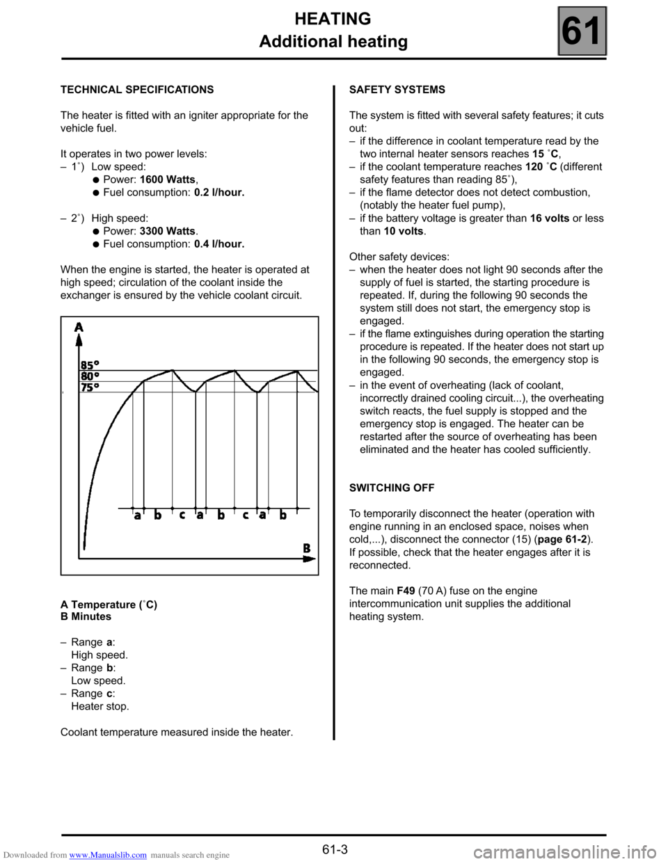
It operates in two power levels:
–1˚) Low speed:
●Power: 1600 Watts,
●Fuel consumption: 0.2 l/hour.
–2˚) High speed:
●Power: 3300 Watts.
●Fuel consumption: 0.4 l/hour.
When the engine is started, the heater is operated at
high speed; circulation of the coolant inside the
exchanger is ensured by the vehicle coolant circuit.
A Temperature (˚C)
B Minutes
–Range a:
High speed.
–Range b:
Low speed.
–Range c:
Heater stop.
Coolant temperature measured inside the heater.SAFETY SYSTEMS
The system is fitted with several safety features; it cuts
out:
–if the difference in coolant temperature read by the
two internal heater sensors reaches 15 ˚C,
–if the coolant temperature reaches 120 ˚C (different
safety features than reading 85˚),
–if the flame detector does not detect combustion,
(notably the heater fuel pump),
–if the battery voltage is greater than 16 volts or less
than 10 volts.
Other safety devices:
–when the heater does not light 90 seconds after the
supply of fuel is started, the starting procedure is
repeated. If, during the following 90 seconds the
system still does not start, the emergency stop is
engaged.
–if the flame extinguishes during operation the starting
procedure is repeated. If the heater does not start up
in the following 90 seconds, the emergency stop is
engaged.
–in the event of overheating (lack of coolant,
incorrectly drained cooling circuit...), the overheating
switch reacts, the fuel supply is stopped and the
emergency stop is engaged. The heater can be
restarted after the source of overheating has been
eliminated and the heater has cooled sufficiently.
SWITCHING OFF
To temporarily disconnect the heater (operation with
engine running in an enclosed space, noises when
cold,...), disconnect the connector (15) (page 61-2).
If possible, check that the heater engages after it is
reconnected.
The main F49 (70 A) fuse on the engine
intercommunication unit supplies the additional
heating system.
Page 51 of 52

Downloaded from www.Manualslib.com manuals search engine HEATING
Additional heating
61
61-6
MAINTENANCE
The principal maintenance operations on this
assembly are:
–replacing the ignition spark plug (5),
–cleaning the filter at the pump inlet (13) (see
page 61-2).
REMOVING - REFITTING COMPONENTS
FUEL PUMP INLET FILTER (13)
Remove the front bumper.
Rotate the pump (12) (see page 61-2) if it turns and
loosen the union covering the filter (13). Clean or
replace the filter if there is a combustion problem.
IGNITION SPARK PLUG
Disconnect and remove the heater without draining the
cooling circuit (use pliers Mot. 453-01).
Remove:
–the turbine cover (1),
–the control unit (9) and the cap (16),
–the spark plug (5) after disconnecting it.
FLAME DETECTOR
Disconnect and remove the heater without draining the
cooling circuit (use pliers Mot. 453-01).
Remove:
–the turbine cover (1),
–the control unit (9) and the cap (16).
Disconnect the flame connector by pulling the flat
terminals from the connector.
Remove the flame detector.
(WARNING: fragile part)COMBUSTION CHAMBER (4) AND EXCHANGER (3)
Remove:
–the flame detector and spark plug,
–the wiring harness fitted on the overheating
detector (8) and the temperature sensor (7),
–the turbine support (1).
Remove the combustion chamber (4) and the
exchanger (3) if necessary.
FAULT FINDING
In case of a fault, check:
–if there is fuel in the tank,
–if the fuses are intact
–if the pipes, connections and electrical unions are
intact,
–if the combustion air ducts or exhaust gas ducts are
blocked (unblock them if necessary).
In the even of combustion with the production of soot,
check:
–if the combustion air ducts or exhaust gas ducts are
blocked (unblock them if necessary),
–if there is a deposit in the exchanger (3) or the
combustion chamber (4); clean these if necessary,
–if the dosing pump flow is correct;
To do this:
●remove the bumper,
●disconnect the electric pump inlet fuel pipe (12),
from the side opposite the fuel filter (13),
●connect a pipe to the electric pump so that the flow
can be collected in a glass at the same height as
the heater,
●start the heater (if necessary, bridge the
temperature sensor located in front of the battery
screen). After approximately 40 seconds, the fuel
arrives and begins to bleed the circuit. Switch off
the ignition. Empty the glass and start again,
collecting the stabilised flow for approximately
30 seconds. Switch off the heater and measure the
quantity of fuel collected.
Normal flow: between 6.8 cm
3 and 7.8 cm3 for
90 seconds of operation.