ESP RENAULT KANGOO Z.E. 2018 User Guide
[x] Cancel search | Manufacturer: RENAULT, Model Year: 2018, Model line: KANGOO Z.E., Model: RENAULT KANGOO Z.E. 2018Pages: 230, PDF Size: 5.03 MB
Page 90 of 230
1.84
PEDESTRIAN HORN
Electric vehicles are particularly quiet.
This system enables you to warn
people of your presence – especially
pedestrians and cyclists.
The system is activated automatically
when the engine is started. The sound
triggers when the vehicle speed is be-
tween 1 and 20 mph (1 and 30 km/h).
Deactivating the system
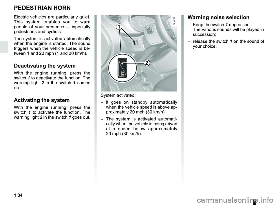
With the engine running, press the
switch 1 to deactivate the function. The
warning light 2 in the switch 1 comes
on.
Activating the system
With the engine running, press the
switch 1 to activate the function. The
warning light 2 in the switch 1 goes out.
System activated:
– it goes on standby automatically
when the vehicle speed is above ap-
proximately 20 mph (30 km/h);
– The system is activated automati- cally when the vehicle is being driven
at a speed below approximately
20 mph (30 km/h).
Warning noise selection
– Keep the switch 1 depressed.The various sounds will be played in
succession;
– release the switch 1 on the sound of
your choice.
2
1
Page 103 of 230
2.3
Stopping the engine
With the engine running, turn the key
back to the “Stop” position St. Warning
light
Ṑ goes out.
Driver’s responsibility
when parking or stopping
the vehicle
Never leave an animal,
child or adult who is not self-suffi-
cient alone in your vehicle, even for
a short time.
They may pose a risk to themselves
or to others by starting the engine,
activating equipment such as the
electric windows or locking the
doors, for example.
Also, in hot and/or sunny weather,
please remember that the tempera-
ture inside the passenger compart-
ment increases very quickly.
RISK OF DEATH OR SERIOUS
INJURY.
Never switch off the igni-
tion before the vehicle has
come to a complete stop.
Switching off the engine di-
sables the assistance equipment:
brakes, power-assisted steering,
etc., and the passive safety devices
such as airbagsand pretensioners.
STARTING, STOPPING THE ENGINE (2/2)
Page 104 of 230

2.4
GEAR CONTROL (1/2)
Operates similar to an automatic gear-
box.
Selector lever 1
The display A on instrument panel indi-
cates the gear lever position as 3.
P : Park
R : Reverse
N : Neutral
D : Forward
Operation
Keeping your foot on the brake pedal
and with the selector lever 1 in position
P, turn the ignition.
Start the motor.
To move out of position P, you must de-
press the brake pedal before pressing
unlocking button 2.
With your foot on the brake pedal
(warning light
c in display A goes
out), move the lever out of position P.
Only engage D or R when the vehi-
cle is stopped, with your foot on the
brake and the accelerator pedal re-
leased.
1
Driving
Put lever 1 in position D.
Hill start
For hill starts, especially after a maxi-
mum traction battery charge and for the
first few miles, we recommend using
the handbrake.
While driving, press the accelerator
pedal to achieve the desired speed.
Reverse
Put lever 1 in position R.
The reversing lights will come on as
soon as reverse gear is selected (with
the ignition on).
32
A
The vehicle can only start if the gear
selector is in position P.
The vehicle can only be started if
the charging cord is unplugged from
the vehicle.
Page 110 of 230
2.10
ENVIRONMENT
Emissions
Your vehicle has been designed to
emit fewer greenhouse gases (CO2)
while in use, and therefore to consume
less fuel (eg. 140 g/km, equivalent to
5.3 l/100 km for a diesel vehicle).
Our vehicles are also equipped with a
particle filter system including a cata-
lytic converter, an oxygen sensor and
an active carbon filter (the latter pre-
vents vapour from the fuel tank being
released into the open air).
For certain diesel vehicles, this system
also has a particle filter to reduce the
volume of soot particles emitted.
Please make your own
contribution towards
protecting the environment
too
– Worn parts replaced in the course of routine vehicle maintenance (vehi-
cle battery, oil filter, air filter, batter-
ies, etc.) and oil containers (empty or
filled with used oil) must be disposed
of through specialist organisations. – At the end of the vehicle’s service
life, it should be sent to approved
centres to ensure that it is recycled.
– In all cases, comply with local legis- lation.
Recycling
Your vehicle is 85% recyclable and
95% recoverable.
To achieve these objectives, many of
the vehicle components have been de-
signed to enable them to be recycled.
The materials and structures have
been carefully designed to allow these
components to be easily removed and
reprocessed by specialist companies.
In order to preserve raw material re-
sources, this vehicle incorporates nu-
merous parts made from recycled plas-
tics or renewable materials (vegetable
or animal-derived materials such as
cotton or wool).
Your vehicle has been designed with
respect for the environment in mind for
its entire service life: during production,
use and at the end of its life.
This commitment is illustrated by the of
the manufacturer eco² signature.Manufacture
Your vehicle has been manufactured at
a factory which complies with a policy
to reduce the environmental impact
on the surrounding areas (reduction of
water and energy consumption, visual
and noise pollution, atmospheric emis-
sions and waste water; sorting and re-
using waste).
Page 111 of 230
2.11
TYRE PRESSURE LOSS WARNING (1/4)
When fitted to the vehicle, this system
notifies the driver if one or more tyres
lose pressure.
Operating principle
Each wheel (except for the emergency
spare wheel) has a sensor in the infla-
tion valve which periodically measures
the tyre pressure while driving.
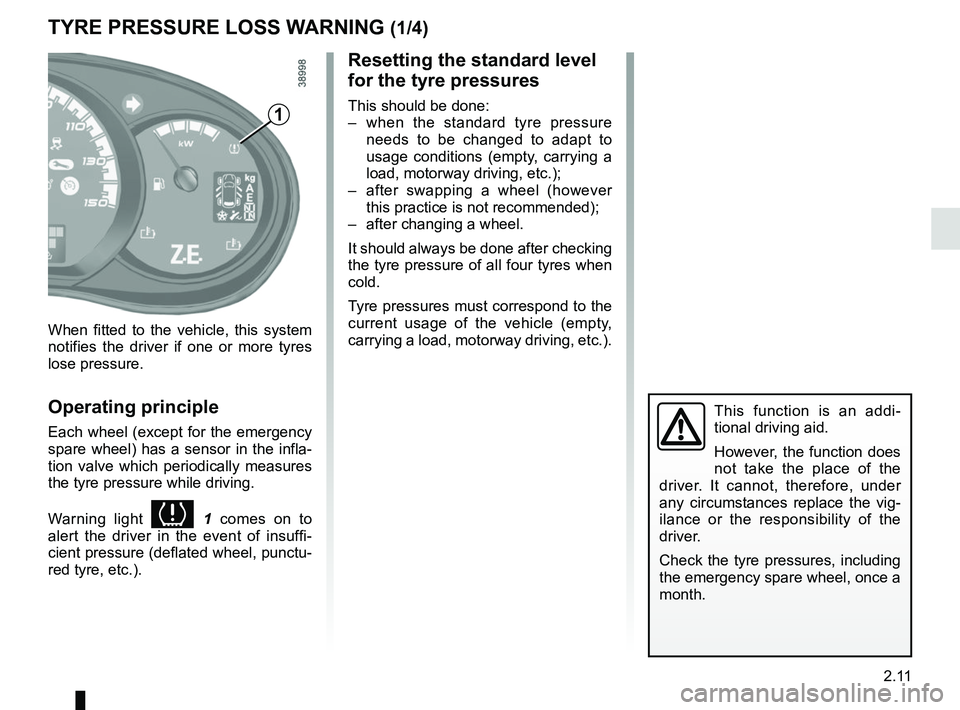
Warning light
1 comes on to
alert the driver in the event of insuffi-
cient pressure (deflated wheel, punctu-
red tyre, etc.).
Resetting the standard level
for the tyre pressures
This should be done:
– when the standard tyre pressure needs to be changed to adapt to
usage conditions (empty, carrying a
load, motorway driving, etc.);
– after swapping a wheel (however this practice is not recommended);
– after changing a wheel.
It should always be done after checking
the tyre pressure of all four tyres when
cold.
Tyre pressures must correspond to the
current usage of the vehicle (empty,
carrying a load, motorway driving, etc.).
This function is an addi-
tional driving aid.
However, the function does
not take the place of the
driver. It cannot, therefore, under
any circumstances replace the vig-
ilance or the responsibility of the
driver.
Check the tyre pressures, including
the emergency spare wheel, once a
month.
1
Page 115 of 230
2.15
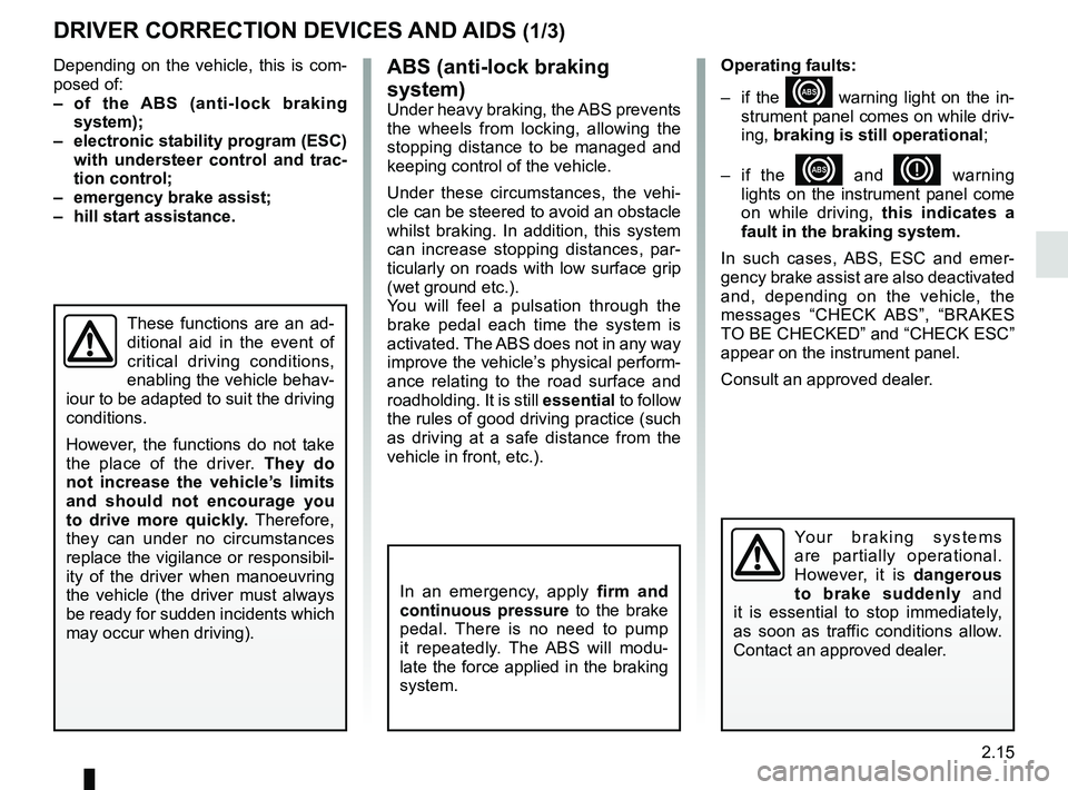
DRIVER CORRECTION DEVICES AND AIDS (1/3)
Depending on the vehicle, this is com-
posed of:
– of the ABS (anti-lock braking
system);
– electronic stability program (ESC) with understeer control and trac-
tion control;
– emergency brake assist;
– hill start assistance.
In an emergency, apply firm and
continuous pressure to the brake
pedal. There is no need to pump
it repeatedly. The ABS will modu-
late the force applied in the braking
system.
These functions are an ad-
ditional aid in the event of
critical driving conditions,
enabling the vehicle behav-
iour to be adapted to suit the driving
conditions.
However, the functions do not take
the place of the driver. They do
not increase the vehicle’s limits
and should not encourage you
to drive more quickly. Therefore,
they can under no circumstances
replace the vigilance or responsibil-
ity of the driver when manoeuvring
the vehicle (the driver must always
be ready for sudden incidents which
may occur when driving).
Your braking systems
are partially operational.
However, it is dangerous
to brake suddenly and
it is essential to stop immediately,
as soon as traffic conditions allow.
Contact an approved dealer.
ABS (anti-lock braking
system)
Under heavy braking, the ABS prevents
the wheels from locking, allowing the
stopping distance to be managed and
keeping control of the vehicle.
Under these circumstances, the vehi-
cle can be steered to avoid an obstacle
whilst braking. In addition, this system
can increase stopping distances, par-
ticularly on roads with low surface grip
(wet ground etc.).
You will feel a pulsation through the
brake pedal each time the system is
activated. The ABS does not in any way
improve the vehicle’s physical perform-
ance relating to the road surface and
roadholding. It is still essential to follow
the rules of good driving practice (such
as driving at a safe distance from the
vehicle in front, etc.). Operating faults:
– if the x warning light on the in-
strument panel comes on while driv-
ing, braking is still operational ;
– if the
x and D warning
lights on the instrument panel come
on while driving, this indicates a
fault in the braking system.
In such cases, ABS, ESC and emer-
gency brake assist are also deactivated
and, depending on the vehicle, the
messages “CHECK ABS”, “BRAKES
TO BE CHECKED” and “CHECK ESC”
appear on the instrument panel.
Consult an approved dealer.
Page 121 of 230
2.21
The cruise control function helps you to
maintain your driving speed at a speed
that you choose, called the cruising
speed.
This cruising speed may be set at any
speed above 18 mph (30 km/h).
CRUISE CONTROL (1/4)
The cruise control function
is in no way linked to the
braking system.
This function is an addi-
tional driving aid. The func-
tion does not take the place
of the driver.
Therefore, it can under no circum-
stances replace the driver’s respon-
sibility to respect speed limits and to
be vigilant (the driver must always
be ready to brake).
Cruise control must not be used in
heavy traffic, on undulating or slip-
pery roads (black ice, aquaplan-
ing, gravel) and during bad weather
(fog, rain, side winds etc.).
There is a risk of accidents.
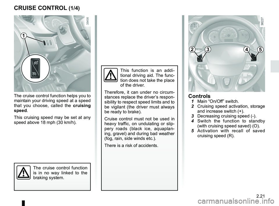
Controls 1 Main “On/Off” switch.
2 Cruising speed activation, storage
and increase switch (+).
3 Decreasing cruising speed (-).
4 Switch the function to standby
(with cruising speed saved) (O).
5 Activation with recall of saved
cruising speed (R).
1
2453
Page 125 of 230

2.25
Operating principle
Ultrasonic sensors in the rear bumper
measure the distance between the ve-
hicle and an obstacle.
This measurement is indicated by
beeps which become more frequent the
closer you come to the obstacle, until
they become a continuous beep when
the vehicle is approximately 30 centi-
metres from the obstacle.
NB: make sure that the ultrasonic sen-
sors are not obscured (by dirt, mud,
snow, etc.).
PARKING DISTANCE CONTROL (1/2)
Operation
When reverse gear is selected, most
objects which are less than approxi-
mately 1.20 metres from the rear of the
vehicle are detected, a beep sounds
and, depending on the vehicle, the dis-
play 1 comes on.
Note: depending on the vehicle, the
screen
1 shows the vehicle surround-
ings alongside the beeps.
This function is an additional aid that indicates the distance between t\
he
vehicle and an obstacle whilst reversing, using sound signals.
Under no circumstances should it replace the driver’s care or responsibil-
ity whilst reversing.
The driver should always be ready for sudden incidents while driving: al\
ways
ensure that there are no small, narrow moving obstacles (such as a chil\
d, animal,
pushchair, bicycle, stone, post, etc.) in the blind spot when manoeuvring.
1
Page 127 of 230
2.27
REVERSING CAMERA (1/2)
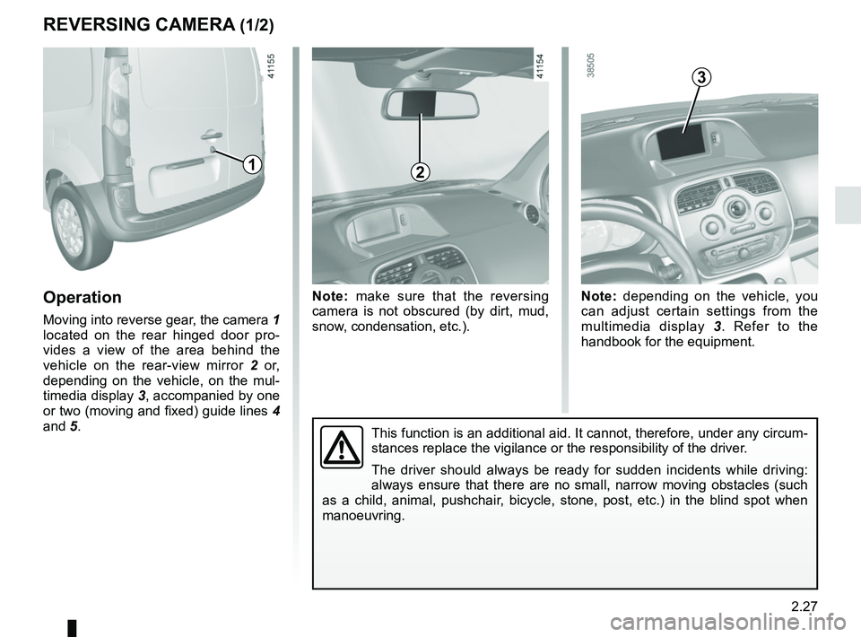
Operation
Moving into reverse gear, the camera 1
located on the rear hinged door pro-
vides a view of the area behind the
vehicle on the rear-view mirror 2 or,
depending on the vehicle, on the mul-
timedia display 3, accompanied by one
or two (moving and fixed) guide lines 4
and 5.
Note: make sure that the reversing
camera is not obscured (by dirt, mud,
snow, condensation, etc.). Note: depending on the vehicle, you
can adjust certain settings from the
multimedia display
3. Refer to the
handbook for the equipment.
This function is an additional aid. It cannot, therefore, under any circ\
um-
stances replace the vigilance or the responsibility of the driver.
The driver should always be ready for sudden incidents while driving:
always ensure that there are no small, narrow moving obstacles (such
as a child, animal, pushchair, bicycle, stone, post, etc.) in the blind spot when
manoeuvring.
2
3
1
Page 145 of 230
3.17
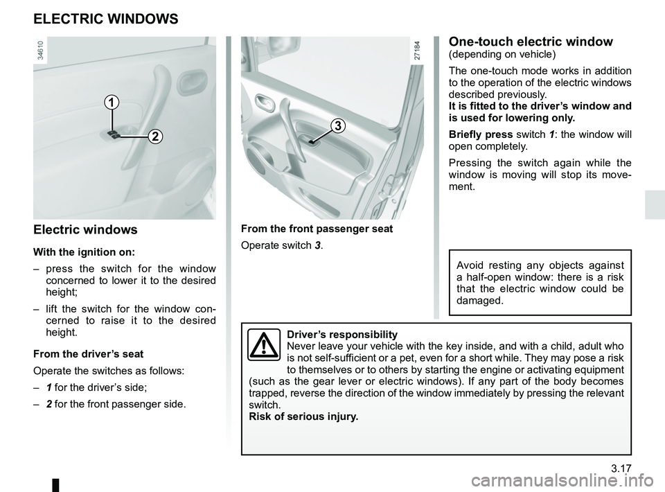
Electric windows
With the ignition on:
– press the switch for the window concerned to lower it to the desired
height;
– lift the switch for the window con- cerned to raise it to the desired
height.
From the driver’s seat
Operate the switches as follows:
– 1 for the driver’s side;
– 2 for the front passenger side.
ELECTRIC WINDOWS
From the front passenger seat
Operate switch 3.
1
23
Driver’s responsibility
Never leave your vehicle with the key inside, and with a child, adult wh\
o
is not self-sufficient or a pet, even for a short while. They may pose a risk
to themselves or to others by starting the engine or activating equipmen\
t
(such as the gear lever or electric windows). If any part of the body \
becomes
trapped, reverse the direction of the window immediately by pressing the\
relevant
switch.
Risk of serious injury.
One-touch electric window(depending on vehicle)
The one-touch mode works in addition
to the operation of the electric windows
described previously.
It is fitted to the driver’s window and
is used for lowering only.
Briefly press switch 1: the window will
open completely.
Pressing the switch again while the
window is moving will stop its move-
ment.
Avoid resting any objects against
a half-open window: there is a risk
that the electric window could be
damaged.