stop start RENAULT KANGOO Z.E. 2018 User Guide
[x] Cancel search | Manufacturer: RENAULT, Model Year: 2018, Model line: KANGOO Z.E., Model: RENAULT KANGOO Z.E. 2018Pages: 230, PDF Size: 5.03 MB
Page 101 of 230
2.1
Section 2: Driving
(Advice on use relating to fuel economy and the environment)
Starting, stopping the engine . . . . . . . . . . . . . . . . . . . . . . . . . . . . . . . . . . . . \
. . . . . . . . . . . . . . . . . . . 2.2
Gear control . . . . . . . . . . . . . . . . . . . . . . . . . . . . . . . . . . . . \
. . . . . . . . . . . . . . . . . . . . . . . . . . . . . . . . 2.4
Handbrake . . . . . . . . . . . . . . . . . . . . . . . . . . . . . . . . . . . . \
. . . . . . . . . . . . . . . . . . . . . . . . . . . . . . . . . 2.5
Driving advice, ECO-driving . . . . . . . . . . . . . . . . . . . . . . . . . . . . . . . . . . . .\
. . . . . . . . . . . . . . . . . . . 2.6
Vehicle range: advice . . . . . . . . . . . . . . . . . . . . . . . . . . . . . . . . . . . .\
. . . . . . . . . . . . . . . . . . . . . . . . 2.8
Environment . . . . . . . . . . . . . . . . . . . . . . . . . . . . . . . . . . . .\
. . . . . . . . . . . . . . . . . . . . . . . . . . . . . . . 2.10
Tyre pressure loss warning . . . . . . . . . . . . . . . . . . . . . . . . . . . . . . . . . . . .\
. . . . . . . . . . . . . . . . . . . . 2.11
Driver correction devices/aids . . . . . . . . . . . . . . . . . . . . . . . . . . . . . . . . . . . . \
. . . . . . . . . . . . . . . . . . 2.15
Speed limiter . . . . . . . . . . . . . . . . . . . . . . . . . . . . . . . . . . . .\
. . . . . . . . . . . . . . . . . . . . . . . . . . . . . . . 2.18
Cruise control . . . . . . . . . . . . . . . . . . . . . . . . . . . . . . . . . . . .\
. . . . . . . . . . . . . . . . . . . . . . . . . . . . . . 2.21
Parking distance control . . . . . . . . . . . . . . . . . . . . . . . . . . . . . . . . . . . .\
. . . . . . . . . . . . . . . . . . . . . . 2.25
Reversing camera . . . . . . . . . . . . . . . . . . . . . . . . . . . . . . . . . . . . \
. . . . . . . . . . . . . . . . . . . . . . . . . . . 2.27
Page 102 of 230
2.2
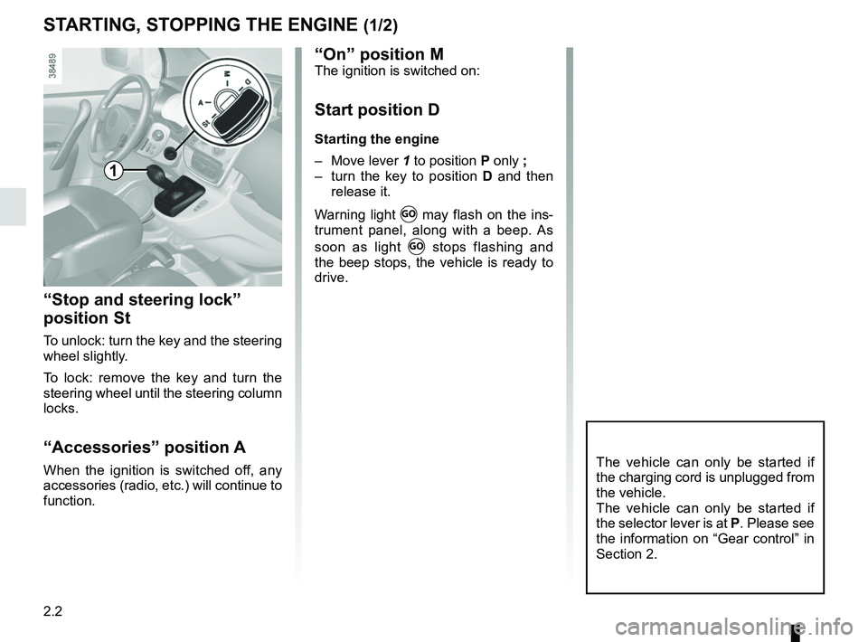
STARTING, STOPPING THE ENGINE (1/2)
“Stop and steering lock”
position St
To unlock: turn the key and the steering
wheel slightly.
To lock: remove the key and turn the
steering wheel until the steering column
locks.
“Accessories” position A
When the ignition is switched off, any
accessories (radio, etc.) will continue to
function.The vehicle can only be started if
the charging cord is unplugged from
the vehicle.
The vehicle can only be started if
the selector lever is at P. Please see
the information on “Gear control” in
Section 2.
1
“On” position MThe ignition is switched on:
Start position D
Starting the engine
– Move lever 1 to position P only ;
– turn the key to position D and then
release it.
Warning light
Ṑ may flash on the ins-
trument panel, along with a beep. As
soon as light
Ṑ stops flashing and
the beep stops, the vehicle is ready to
drive.
Page 103 of 230
2.3
Stopping the engine
With the engine running, turn the key
back to the “Stop” position St. Warning
light
Ṑ goes out.
Driver’s responsibility
when parking or stopping
the vehicle
Never leave an animal,
child or adult who is not self-suffi-
cient alone in your vehicle, even for
a short time.
They may pose a risk to themselves
or to others by starting the engine,
activating equipment such as the
electric windows or locking the
doors, for example.
Also, in hot and/or sunny weather,
please remember that the tempera-
ture inside the passenger compart-
ment increases very quickly.
RISK OF DEATH OR SERIOUS
INJURY.
Never switch off the igni-
tion before the vehicle has
come to a complete stop.
Switching off the engine di-
sables the assistance equipment:
brakes, power-assisted steering,
etc., and the passive safety devices
such as airbagsand pretensioners.
STARTING, STOPPING THE ENGINE (2/2)
Page 104 of 230

2.4
GEAR CONTROL (1/2)
Operates similar to an automatic gear-
box.
Selector lever 1
The display A on instrument panel indi-
cates the gear lever position as 3.
P : Park
R : Reverse
N : Neutral
D : Forward
Operation
Keeping your foot on the brake pedal
and with the selector lever 1 in position
P, turn the ignition.
Start the motor.
To move out of position P, you must de-
press the brake pedal before pressing
unlocking button 2.
With your foot on the brake pedal
(warning light
c in display A goes
out), move the lever out of position P.
Only engage D or R when the vehi-
cle is stopped, with your foot on the
brake and the accelerator pedal re-
leased.
1
Driving
Put lever 1 in position D.
Hill start
For hill starts, especially after a maxi-
mum traction battery charge and for the
first few miles, we recommend using
the handbrake.
While driving, press the accelerator
pedal to achieve the desired speed.
Reverse
Put lever 1 in position R.
The reversing lights will come on as
soon as reverse gear is selected (with
the ignition on).
32
A
The vehicle can only start if the gear
selector is in position P.
The vehicle can only be started if
the charging cord is unplugged from
the vehicle.
Page 115 of 230
2.15
DRIVER CORRECTION DEVICES AND AIDS (1/3)
Depending on the vehicle, this is com-
posed of:
– of the ABS (anti-lock braking
system);
– electronic stability program (ESC) with understeer control and trac-
tion control;
– emergency brake assist;
– hill start assistance.
In an emergency, apply firm and
continuous pressure to the brake
pedal. There is no need to pump
it repeatedly. The ABS will modu-
late the force applied in the braking
system.
These functions are an ad-
ditional aid in the event of
critical driving conditions,
enabling the vehicle behav-
iour to be adapted to suit the driving
conditions.
However, the functions do not take
the place of the driver. They do
not increase the vehicle’s limits
and should not encourage you
to drive more quickly. Therefore,
they can under no circumstances
replace the vigilance or responsibil-
ity of the driver when manoeuvring
the vehicle (the driver must always
be ready for sudden incidents which
may occur when driving).
Your braking systems
are partially operational.
However, it is dangerous
to brake suddenly and
it is essential to stop immediately,
as soon as traffic conditions allow.
Contact an approved dealer.
ABS (anti-lock braking
system)
Under heavy braking, the ABS prevents
the wheels from locking, allowing the
stopping distance to be managed and
keeping control of the vehicle.
Under these circumstances, the vehi-
cle can be steered to avoid an obstacle
whilst braking. In addition, this system
can increase stopping distances, par-
ticularly on roads with low surface grip
(wet ground etc.).
You will feel a pulsation through the
brake pedal each time the system is
activated. The ABS does not in any way
improve the vehicle’s physical perform-
ance relating to the road surface and
roadholding. It is still essential to follow
the rules of good driving practice (such
as driving at a safe distance from the
vehicle in front, etc.). Operating faults:
– if the x warning light on the in-
strument panel comes on while driv-
ing, braking is still operational ;
– if the
x and D warning
lights on the instrument panel come
on while driving, this indicates a
fault in the braking system.
In such cases, ABS, ESC and emer-
gency brake assist are also deactivated
and, depending on the vehicle, the
messages “CHECK ABS”, “BRAKES
TO BE CHECKED” and “CHECK ESC”
appear on the instrument panel.
Consult an approved dealer.
Page 117 of 230
2.17
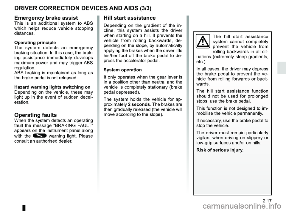
Emergency brake assistThis is an additional system to ABS
which helps reduce vehicle stopping
distances.
Operating principle
The system detects an emergency
braking situation. In this case, the brak-
ing assistance immediately develops
maximum power and may trigger ABS
regulation.
ABS braking is maintained as long as
the brake pedal is not released.
Hazard warning lights switching on
Depending on the vehicle, these may
light up in the event of sudden decel-
eration.
Operating faultsWhen the system detects an operating
fault the message “BRAKING FAULT”
appears on the instrument panel along
with the
© warning light. Please
consult an authorised dealer.
DRIVER CORRECTION DEVICES AND AIDS (3/3)
Hill start assistance
Depending on the gradient of the in-
cline, this system assists the driver
when starting on a hill. It prevents the
vehicle from rolling backwards, de-
pending on the slope, by automatically
applying the brakes when the driver lifts
his/her foot off the brake pedal to de-
press the accelerator pedal.
System operation
It only operates when the gear lever is
in a position other than neutral and the
vehicle is completely stationary (brake
pedal depressed).
The system holds the vehicle for ap-
proximately 2 seconds. The brakes are
then gradually released (the vehicle will
move according to the slope).
The hill start assistance
system cannot completely
prevent the vehicle from
rolling backwards in all sit-
uations (extremely steep gradients,
etc.).
In all cases, the driver may depress
the brake pedal to prevent the ve-
hicle from rolling forwards or back-
wards.
The hill start assistance function
should not be used for prolonged
stops: use the brake pedal.
This function is not designed to im-
mobilise the vehicle permanently.
If necessary, use the brake pedal to
stop the vehicle.
The driver must remain particularly
vigilant when driving on slippery or
low-grip surfaces and/or on hills.
Risk of serious injury.
Page 134 of 230
3.6
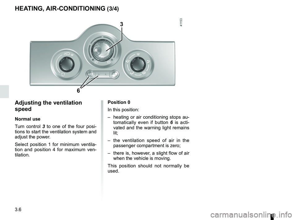
Adjusting the ventilation
speed
Normal use
Turn control 3 to one of the four posi-
tions to start the ventilation system and
adjust the power.
Select position 1 for minimum ventila-
tion and position 4 for maximum ven-
tilation.
HEATING, AIR-CONDITIONING (3/4)
3
6
Position 0
In this position:
– heating or air conditioning stops au- tomatically even if button 6 is acti-
vated and the warning light remains
lit;
– the ventilation speed of air in the passenger compartment is zero;
– there is, however, a slight flow of air when the vehicle is moving.
This position should not normally be
used.
Page 140 of 230
3.12
AIR CONDITIONING: information and operating instructions (1/2)
Do not open the refriger-
ant fluid circuit. The fluid
may damage eyes or skin.
Operating faults
As a general rule, contact your ap-
proved Dealer in the event of an oper-
ating fault.
– Reduction in de-icing, demisting or air conditioning performance.
This may be caused by the passen-
ger compartment filter cartridge be-
coming clogged.
– No cold air is being produced.
Check that the controls are set cor-
rectly and that the fuses are sound.
Otherwise, switch off the system.
Range
It is normal to notice an increase in
energy usage when the air conditioning
is operating.
Switch off the system when it is not re-
quired.
Advice for reducing consumption
and helping to preserve the environ-
ment
Drive with the air vents on and the win-
dows closed.
If the vehicle has been parked in the
sun, open the doors for a few moments
to let the hot air escape before starting
the engine.
MaintenanceRefer to the Maintenance Document
for your vehicle for the inspection fre-
quency.
Below approximately 10°C, with the
engine off it is normal to notice cold
air enter the passenger compart-
ment via the vents when ventilation
has not stopped (refer to the infor-
mation on “Heating, air condition-
ing” in section 3). It is recommended
to position the ventilation control at
0 in case of brief stops.
Presence of water under the
vehicle.
After prolonged use of the air condi-
tioning system, it is normal for water
to be present under the vehicle. This is
caused by condensation.
Noise
Each time the ignition is switched off,
the ventilation will be switched off after
about ten seconds.
Vehicles equipped with
mode ECO
Once activated, ECO mode may
reduce air conditioning perform-
ance. Please refer to the informa-
tion on “Driving advice, Eco-driving”
in Section 2.
Use the air conditioning system reg-
ularly, even in cold weather, running
it at least once a month for approxi-
mately 5 minutes.
Page 141 of 230
3.13
AIR CONDITIONING: information and operating instructions (2/2)
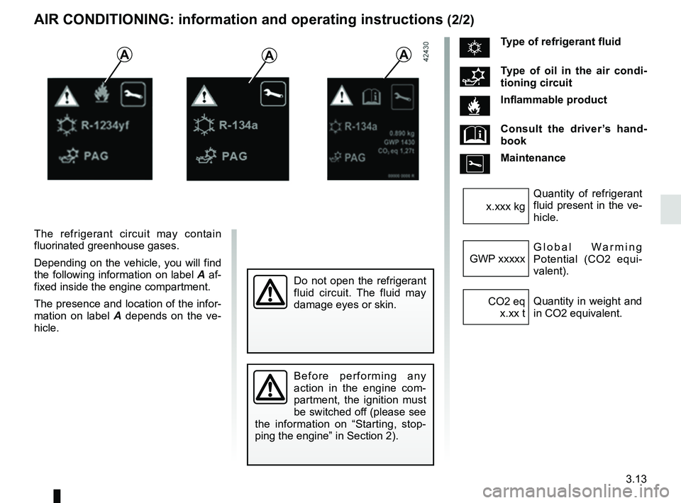
The refrigerant circuit may contain
fluorinated greenhouse gases.
Depending on the vehicle, you will find
the following information on label A af-
fixed inside the engine compartment.
The presence and location of the infor-
mation on label A depends on the ve-
hicle.
AAA
Do not open the refrigerant
fluid circuit. The fluid may
damage eyes or skin.
ÑType of refrigerant fluid
Type of oil in the air condi-
tioning circuit
Inflammable product
Consult the driver’s hand-
book
Maintenance
Quantity of refrigerant
fluid present in the ve-
hicle.
x.xxx kg
Global Warming
Potential (CO2 equi-
valent).
GWP xxxxx
Quantity in weight and
in CO2 equivalent.
CO2 eq
x.xx t
Before performing any
action in the engine com-
partment, the ignition must
be switched off (please see
the information on “Starting, stop-
ping the engine” in Section 2).
Page 145 of 230
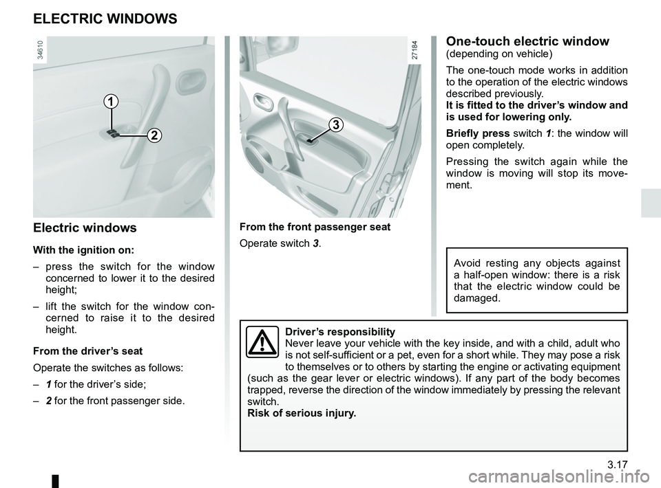
3.17
Electric windows
With the ignition on:
– press the switch for the window concerned to lower it to the desired
height;
– lift the switch for the window con- cerned to raise it to the desired
height.
From the driver’s seat
Operate the switches as follows:
– 1 for the driver’s side;
– 2 for the front passenger side.
ELECTRIC WINDOWS
From the front passenger seat
Operate switch 3.
1
23
Driver’s responsibility
Never leave your vehicle with the key inside, and with a child, adult wh\
o
is not self-sufficient or a pet, even for a short while. They may pose a risk
to themselves or to others by starting the engine or activating equipmen\
t
(such as the gear lever or electric windows). If any part of the body \
becomes
trapped, reverse the direction of the window immediately by pressing the\
relevant
switch.
Risk of serious injury.
One-touch electric window(depending on vehicle)
The one-touch mode works in addition
to the operation of the electric windows
described previously.
It is fitted to the driver’s window and
is used for lowering only.
Briefly press switch 1: the window will
open completely.
Pressing the switch again while the
window is moving will stop its move-
ment.
Avoid resting any objects against
a half-open window: there is a risk
that the electric window could be
damaged.