Rear indicator RENAULT KOLEOS 2018 User Guide
[x] Cancel search | Manufacturer: RENAULT, Model Year: 2018, Model line: KOLEOS, Model: RENAULT KOLEOS 2018Pages: 332, PDF Size: 8.91 MB
Page 162 of 332
2.58
Operating faults
If the system detects a fault, the mes-
sage “Check blind spot alert” is dis-
played on the instrument panel. Consult
an authorised dealer.
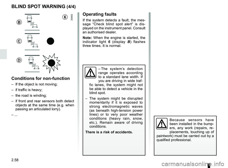
Note: When the engine is started, the
indicator light 6 (display B) flashes
three times. It is normal.
– The system’s detection
range operates according
to a standard lane width. If
you are driving in wide traf-
fic lanes, the system might not
be able to detect a vehicle in the
blind spot.
– The system might be disrupted momentarily if it is exposed to
strong electromagnetic waves
(as beneath high-tension power
lines) or to very poor weather
conditions (heavy rain, snow,
etc.). Remain aware of driving
conditions.
There is a risk of accidents.
BLIND SPOT WARNING (4/4)
Because sensors have
been installed in the bump-
ers, any work (repairs, re-
placements, touching up of
paintwork) must be carried out by a
qualified professional.
6
B
C
D
Conditions for non-function
– If the object is not moving;
– if traffic is heavy;
– the road is winding;
– if front and rear sensors both detect objects at the same time (e.g. when
passing an articulated lorry).
– ...
Page 200 of 332
3.4
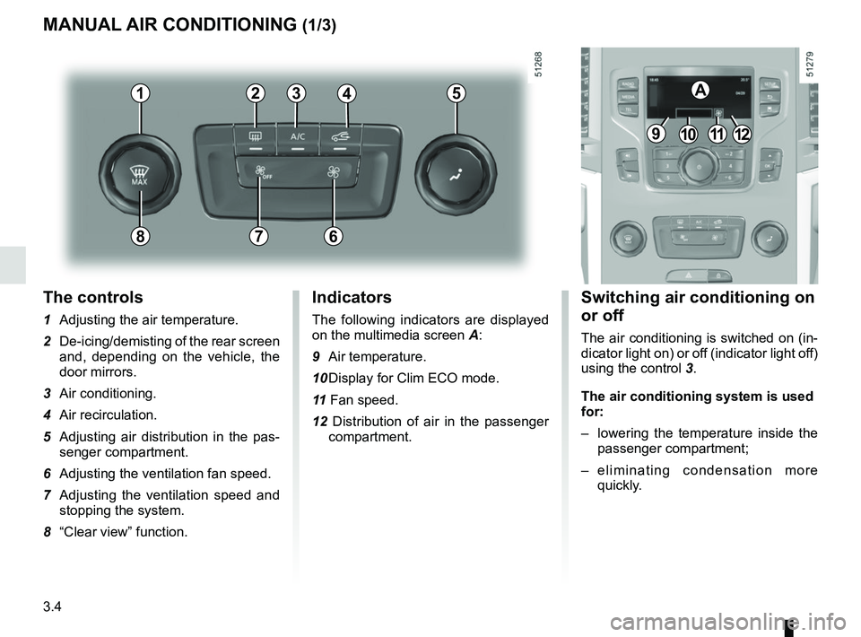
The controls
1 Adjusting the air temperature.
2 De-icing/demisting of the rear screen and, depending on the vehicle, the
door mirrors.
3 Air conditioning.
4 Air recirculation.
5 Adjusting air distribution in the pas- senger compartment.
6 Adjusting the ventilation fan speed.
7 Adjusting the ventilation speed and stopping the system.
8 “Clear view” function.
MANUAL AIR CONDITIONING (1/3)
Switching air conditioning on
or off
The air conditioning is switched on (in-
dicator light on) or off (indicator light off)
using the control 3.
The air conditioning system is used
for:
– lowering the temperature inside the
passenger compartment;
– eliminating condensation more quickly.
Indicators
The following indicators are displayed
on the multimedia screen A:
9 Air temperature.
10 Display for Clim ECO mode.
11 Fan speed.
12 Distribution of air in the passenger compartment.
21
7
34
9101112
A5
68
Page 202 of 332
3.6
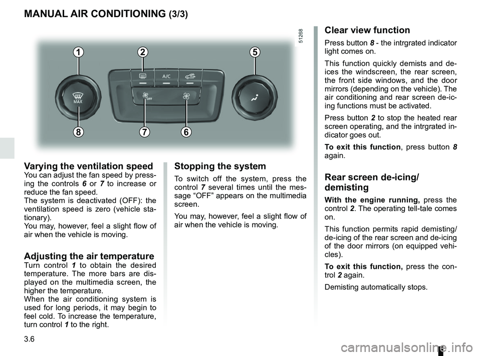
Varying the ventilation speedYou can adjust the fan speed by press-
ing the controls 6 or 7 to increase or
reduce the fan speed.
The system is deactivated (OFF): the
ventilation speed is zero (vehicle sta-
tionary).
You may, however, feel a slight flow of
air when the vehicle is moving.
Adjusting the air temperatureTurn control 1 to obtain the desired
temperature. The more bars are dis-
played on the multimedia screen, the
higher the temperature.
When the air conditioning system is
used for long periods, it may begin to
feel cold. To increase the temperature,
turn control 1 to the right.
MANUAL AIR CONDITIONING (3/3)
Stopping the system
To switch off the system, press the
control 7 several times until the mes-
sage “OFF” appears on the multimedia
screen.
You may, however, feel a slight flow of
air when the vehicle is moving.
Clear view function
Press button 8 - the intrgrated indicator
light comes on.
This function quickly demists and de-
ices the windscreen, the rear screen,
the front side windows, and the door
mirrors (depending on the vehicle). The
air conditioning and rear screen de-ic-
ing functions must be activated.
Press button 2 to stop the heated rear
screen operating, and the intrgrated in-
dicator goes out.
To exit this function , press button 8
again.
Rear screen de-icing/
demisting
With the engine running, press the
control 2. The operating tell-tale comes
on.
This function permits rapid demisting/
de-icing of the rear screen and de-icing
of the door mirrors (on equipped vehi-
cles).
To exit this function, press the con-
trol 2 again.
Demisting automatically stops.
21
7
5
68
Page 208 of 332
3.12
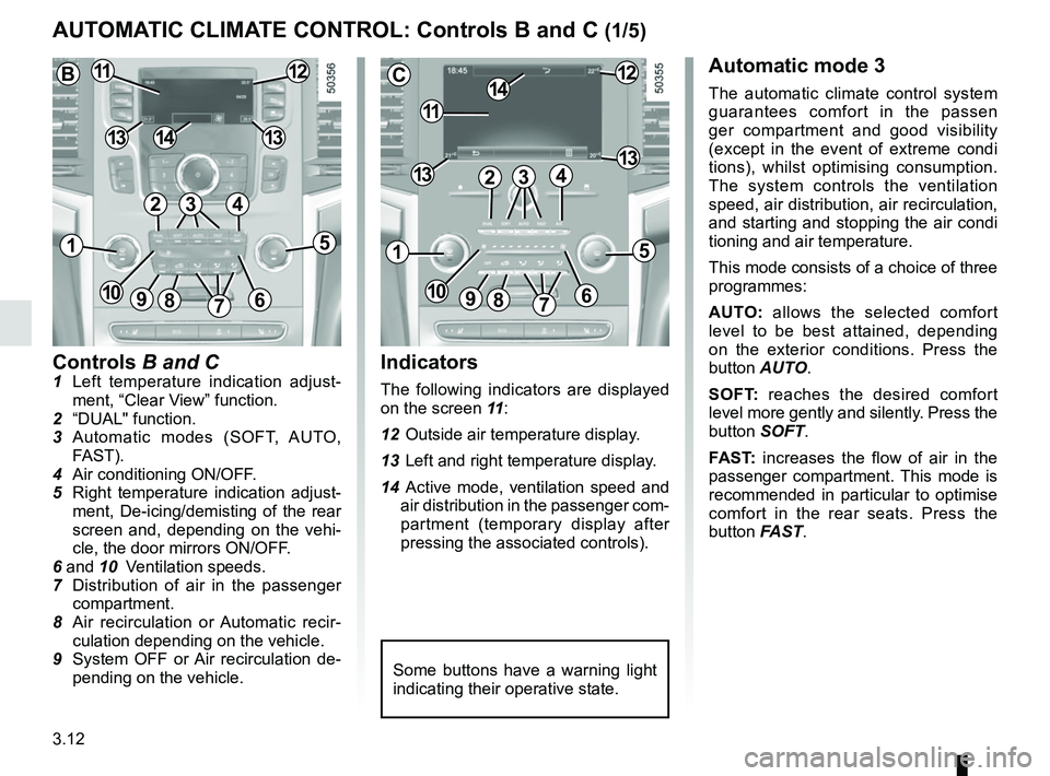
Controls B and C1 Left temperature indication adjust-ment, “Clear View” function.
2 “DUAL" function.
3 Automatic modes (SOFT, AUTO, FAST).
4 Air conditioning ON/OFF.
5 Right temperature indication adjust- ment, De-icing/demisting of the rear
screen and, depending on the vehi-
cle, the door mirrors ON/OFF.
6 and 10 Ventilation speeds.
7 Distribution of air in the passenger
compartment.
8 Air recirculation or Automatic recir- culation depending on the vehicle.
9 System OFF or Air recirculation de- pending on the vehicle.
AUTOMATIC CLIMATE CONTROL: Controls B and C (1/5)
Indicators
The following indicators are displayed
on the screen 11 :
12 Outside air temperature display.
13 Left and right temperature display.
14 Active mode, ventilation speed and air distribution in the passenger com-
partment (temporary display after
pressing the associated controls).
Automatic mode 3
The automatic climate control system
guarantees comfort in the passen
ger compartment and good visibility
(except in the event of extreme condi
tions), whilst optimising consumption.
The system controls the ventilation
speed, air distribution, air recirculation,
and starting and stopping the air condi
tioning and air temperature.
This mode consists of a choice of three
programmes:
AUTO: allows the selected comfort
level to be best attained, depending
on the exterior conditions. Press the
button AUTO.
SOFT: reaches the desired comfort
level more gently and silently. Press the
button SOFT.
FAST: increases the flow of air in the
passenger compartment. This mode is
recommended in particular to optimise
comfort in the rear seats. Press the
button FAST.
Some buttons have a warning light
indicating their operative state.
C
11
1412
131342
1
91086
5
7
3
13
B1112
1413
42
15
7
3
69810
Page 231 of 332
3.35
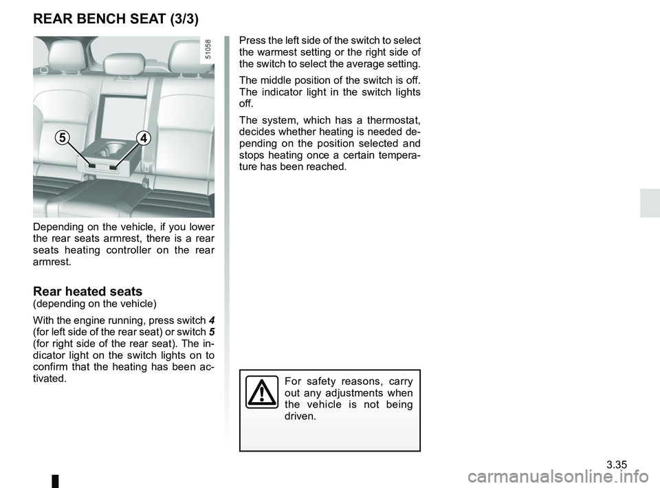
Depending on the vehicle, if you lower
the rear seats armrest, there is a rear
seats heating controller on the rear
armrest.
Rear heated seats(depending on the vehicle)
With the engine running, press switch 4
(for left side of the rear seat) or switch 5
(for right side of the rear seat). The in-
dicator light on the switch lights on to
confirm that the heating has been ac-
tivated. Press the left side of the switch to select
the warmest setting or the right side of
the switch to select the average setting.
The middle position of the switch is off.
The indicator light in the switch lights
off.
The system, which has a thermostat,
decides whether heating is needed de-
pending on the position selected and
stops heating once a certain tempera-
ture has been reached.
REAR BENCH SEAT (3/3)
For safety reasons, carry
out any adjustments when
the vehicle is not being
driven.
45
Page 274 of 332
5.10
TYRES (1/3)
Maintaining the tyres
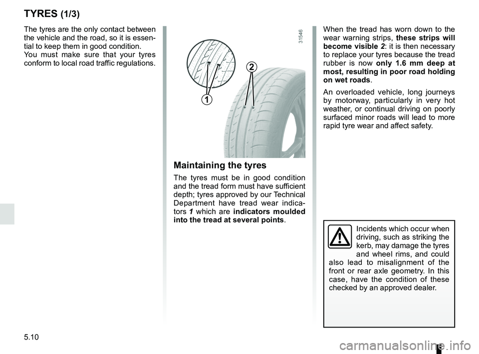
The tyres must be in good condition
and the tread form must have sufficient
depth; tyres approved by our Technical
Department have tread wear indica-
tors 1 which are indicators moulded
into the tread at several points .
The tyres are the only contact between
the vehicle and the road, so it is essen-
tial to keep them in good condition.
You must make sure that your tyres
conform to local road traffic regulations.
When the tread has worn down to the
wear warning strips,
these strips will
become visible 2: it is then necessary
to replace your tyres because the tread
rubber is now only 1.6 mm deep at
most, resulting in poor road holding
on wet roads.
An overloaded vehicle, long journeys
by motorway, particularly in very hot
weather, or continual driving on poorly
surfaced minor roads will lead to more
rapid tyre wear and affect safety.
Incidents which occur when
driving, such as striking the
kerb, may damage the tyres
and wheel rims, and could
also lead to misalignment of the
front or rear axle geometry. In this
case, have the condition of these
checked by an approved dealer.
2
1
Page 280 of 332
5.16
REAR AND SIDE LIGHTS: changing bulbs (1/3)
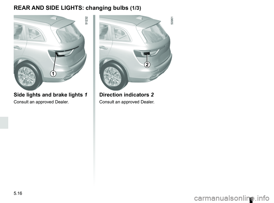
Side lights and brake lights 1
Consult an approved Dealer.
1
Direction indicators 2
Consult an approved Dealer.
2
Page 282 of 332
5.18
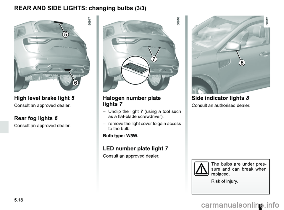
Halogen number plate
lights 7
– Unclip the light 7 (using a tool such
as a flat-blade screwdriver).
– remove the light cover to gain access to the bulb.
Bulb type: W5W.
LED number plate light 7
Consult an approved dealer.
REAR AND SIDE LIGHTS: changing bulbs (3/3)
The bulbs are under pres-
sure and can break when
replaced.
Risk of injury.
Side indicator lights 8
Consult an authorised dealer.
8
High level brake light 5
Consult an approved dealer.
Rear fog lights 6
Consult an approved dealer.
5
7
6
Page 304 of 332
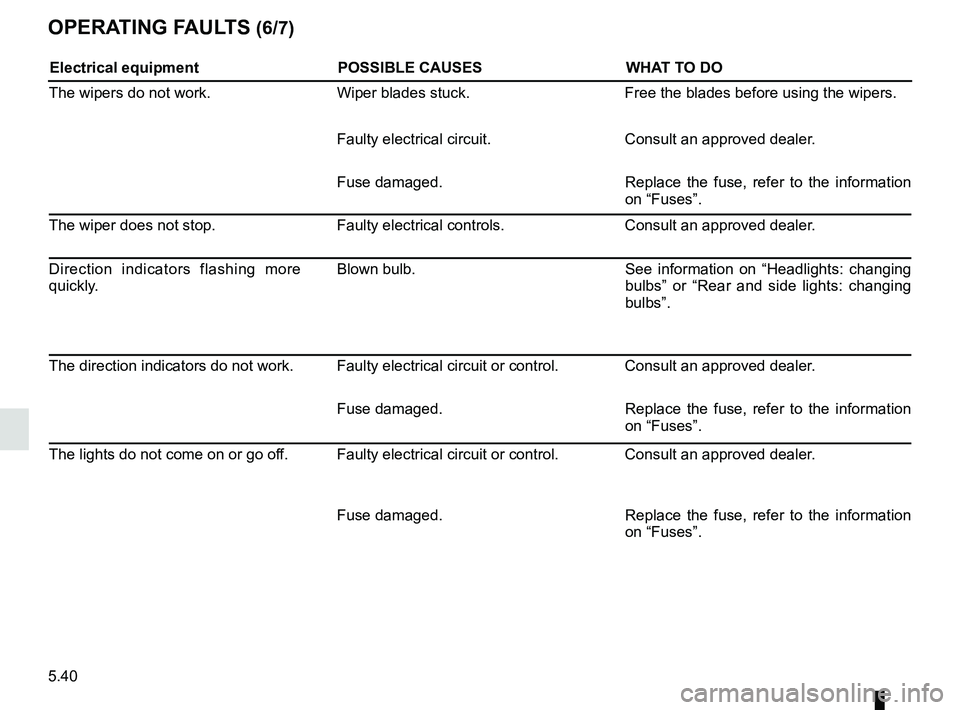
5.40
OPERATING FAULTS (6/7)
Electrical equipmentPOSSIBLE CAUSESWHAT TO DO
The wipers do not work. Wiper blades stuck. Free the blades before using the wipers.
Faulty electrical circuit. Consult an approved dealer.
Fuse damaged. Replace the fuse, refer to the information
on “Fuses”.
The wiper does not stop. Faulty electrical controls.Consult an approved dealer.
Direction indicators flashing more
quickly. Blown bulb.
See information on “Headlights: changing
bulbs” or “Rear and side lights: changing
bulbs”.
The direction indicators do not work. Faulty electrical circuit or control. Consult an approved dealer. Fuse damaged. Replace the fuse, refer to the information
on “Fuses”.
The lights do not come on or go off. Faulty electrical circuit or control. Consult an approved dealer.
Fuse damaged. Replace the fuse, refer to the information
on “Fuses”.