RENAULT MASTER 2016 X62 / 2.G Owners Manual
Manufacturer: RENAULT, Model Year: 2016, Model line: MASTER, Model: RENAULT MASTER 2016 X62 / 2.GPages: 284, PDF Size: 6.69 MB
Page 221 of 284
5.13
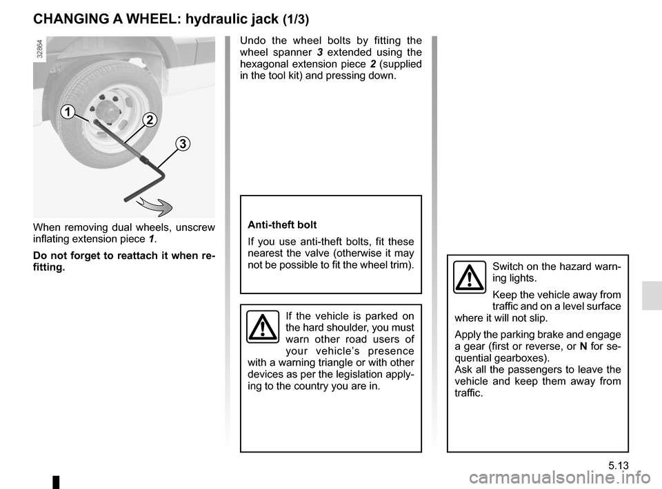
When removing dual wheels, unscrew
inflating extension piece 1.
Do not forget to reattach it when re-
fitting. Undo the wheel bolts by fitting the
wheel spanner
3 extended using the
hexagonal extension piece 2 (supplied
in the tool kit) and pressing down.
1
CHANGING A WHEEL: hydraulic jack (1/3)
Switch on the hazard warn-
ing lights.
Keep the vehicle away from
traffic and on a level surface
where it will not slip.
Apply the parking brake and engage
a gear (first or reverse, or N for se-
quential gearboxes).
Ask all the passengers to leave the
vehicle and keep them away from
traffic.
If the vehicle is parked on
the hard shoulder, you must
warn other road users of
your vehicle’s presence
with a warning triangle or with other
devices as per the legislation apply-
ing to the country you are in.
Anti-theft bolt
If you use anti-theft bolts, fit these
nearest the valve (otherwise it may
not be possible to fit the wheel trim).
2
3
Page 222 of 284
5.14
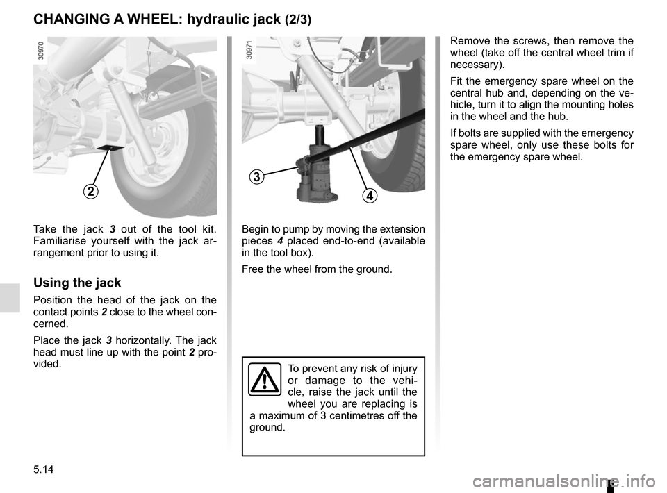
Begin to pump by moving the extension
pieces 4 placed end-to-end (available
in the tool box).
Free the wheel from the ground.Take the jack 3 out of the tool kit.
Familiarise yourself with the jack ar-
rangement prior to using it.
Using the jack
Position the head of the jack on the
contact points 2 close to the wheel con- cerned.
Place the jack 3 horizontally. The jack
head must line up with the point 2 pro-
vided.
3
CHANGING A WHEEL: hydraulic jack (2/3)
24
To prevent any risk of injury
or damage to the vehi-
cle, raise the jack until the
wheel you are replacing is
a maximum of 3 centimetres off the
ground.
Remove the screws, then remove the
wheel (take off the central wheel trim if
necessary).
Fit the emergency spare wheel on the
central hub and, depending on the ve-
hicle, turn it to align the mounting holes
in the wheel and the hub.
If bolts are supplied with the emergency
spare wheel, only use these bolts for
the emergency spare wheel.
Page 223 of 284
5.15
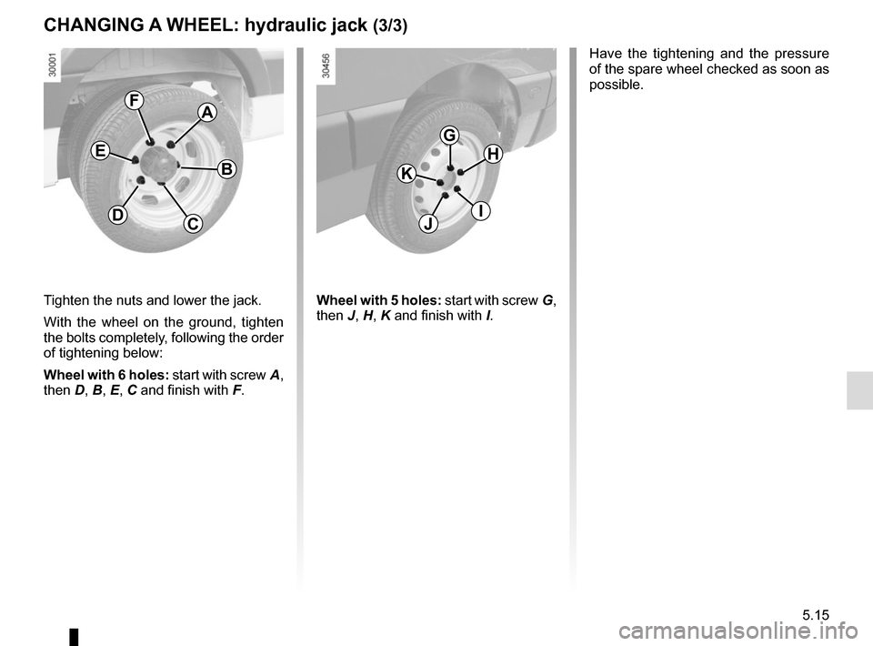
Tighten the nuts and lower the jack.
With the wheel on the ground, tighten
the bolts completely, following the order
of tightening below:
Wheel with 6 holes: start with screw A,
then D, B, E, C and finish with F.
A
B
CD
E
F
G
I
K
H
J
CHANGING A WHEEL: hydraulic jack (3/3)
Have the tightening and the pressure
of the spare wheel checked as soon as
possible.
Wheel with 5 holes: start with screw G,
then J, H, K and finish with I.
Page 224 of 284
5.16
CHANGING A WHEEL: jack (1/2)
2
If the vehicle is parked on
the hard shoulder, you must
warn other road users of
your vehicle’s presence
with a warning triangle or with other
devices as per the legislation ap-
plying to the country you are in.
Switch on the hazard war-
ning lights.
Keep the vehicle away from
traffic and on a level surface
where it will not slip.
Apply the parking brake and engage
a gear (first or reverse, or N for se-
quential gearboxes).
Ask all the passengers to leave the
vehicle and keep them away from
traffic.
To prevent any risk of injury
or damage to the vehi-
cle, raise the jack until the
wheel you are replacing is
a maximum of 3 centimetres off the
ground.
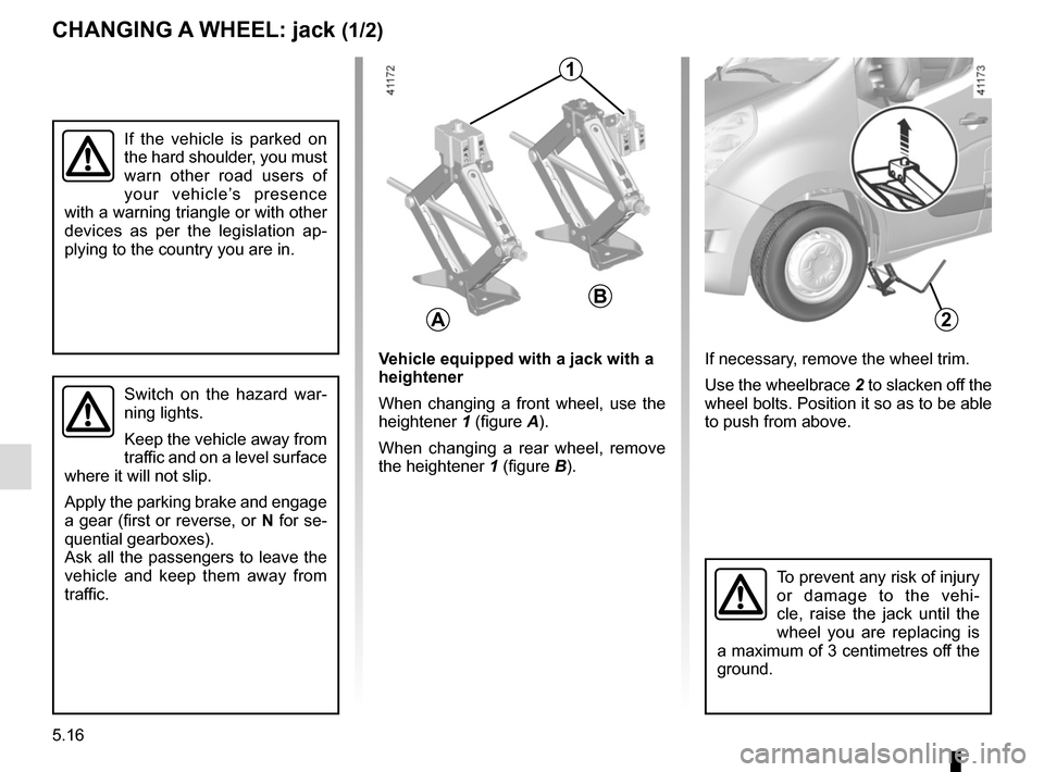
If necessary, remove the wheel trim.
Use the wheelbrace 2 to slacken off the
wheel bolts. Position it so as to be able
to push from above.Vehicle equipped with a jack with a
heightener
When changing a front wheel, use the
heightener 1 (figure A).
When changing a rear wheel, remove
the heightener 1 (figure B).
A
B
1
Page 225 of 284
5.17
CHANGING A WHEEL: jack (2/2)
If you have a puncture, re-
place the wheel as soon as
possible.
A tyre which has been
punctured should always be inspec-
ted (and repaired, where possible)
by a specialist.
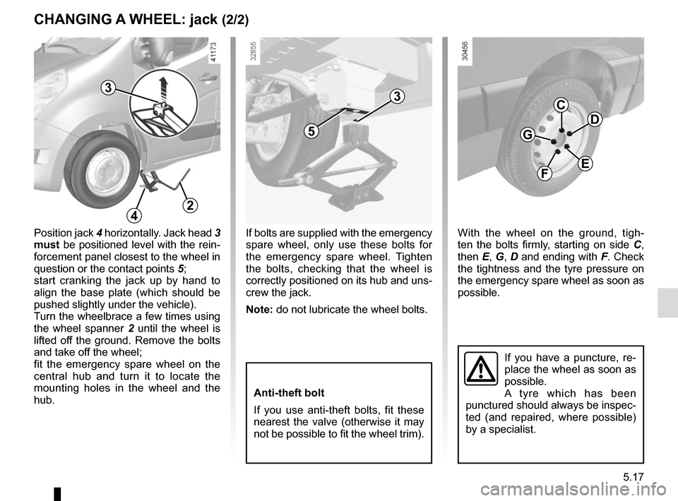
With the wheel on the ground, tigh-
ten the bolts firmly, starting on side C,
then E, G, D and ending with F. Check
the tightness and the tyre pressure on
the emergency spare wheel as soon as
possible.
C
E
G
D
F
If bolts are supplied with the emergency
spare wheel, only use these bolts for
the emergency spare wheel. Tighten
the bolts, checking that the wheel is
correctly positioned on its hub and uns-
crew the jack.
Note: do not lubricate the wheel bolts.
Anti-theft bolt
If you use anti-theft bolts, fit these
nearest the valve (otherwise it may
not be possible to fit the wheel trim).
Position jack 4 horizontally. Jack head 3
must be positioned level with the rein-
forcement panel closest to the wheel in
question or the contact points 5;
start cranking the jack up by hand to
align the base plate (which should be
pushed slightly under the vehicle).
Turn the wheelbrace a few times using
the wheel spanner 2 until the wheel is
lifted off the ground. Remove the bolts
and take off the wheel;
fit the emergency spare wheel on the
central hub and turn it to locate the
mounting holes in the wheel and the
hub.
3
5
3
24
Page 226 of 284
5.18
TYRES (1/3)
Maintaining the tyres
The tyres must be in good condition
and the tread form must have sufficient
depth; tyres approved by our Technical
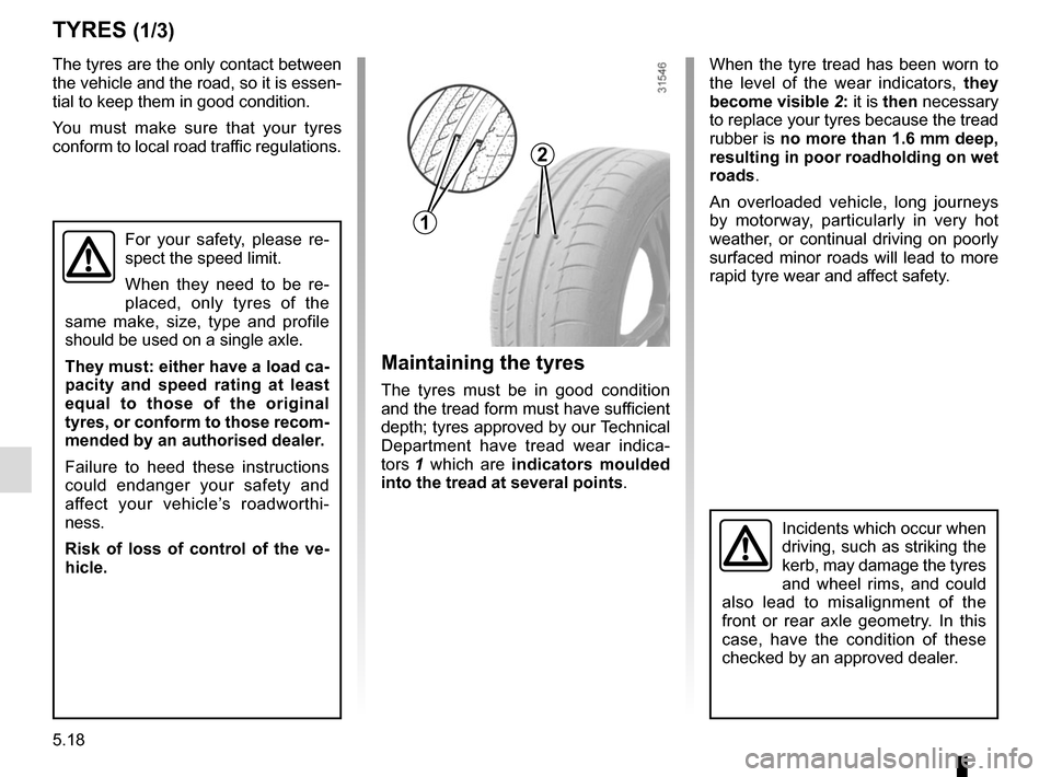
Department have tread wear indica-
tors 1 which are indicators moulded
into the tread at several points .
The tyres are the only contact between
the vehicle and the road, so it is essen-
tial to keep them in good condition.
You must make sure that your tyres
conform to local road traffic regulations.
When the tyre tread has been worn to
the level of the wear indicators,
they
become visible 2: it is then necessary
to replace your tyres because the tread
rubber is no more than 1.6 mm deep,
resulting in poor roadholding on wet
roads.
An overloaded vehicle, long journeys
by motorway, particularly in very hot
weather, or continual driving on poorly
surfaced minor roads will lead to more
rapid tyre wear and affect safety.
For your safety, please re-
spect the speed limit.
When they need to be re-
placed, only tyres of the
same make, size, type and profile
should be used on a single axle.
They must: either have a load ca-
pacity and speed rating at least
equal to those of the original
tyres, or conform to those recom-
mended by an authorised dealer.
Failure to heed these instructions
could endanger your safety and
affect your vehicle’s roadworthi-
ness.
Risk of loss of control of the ve-
hicle.
Incidents which occur when
driving, such as striking the
kerb, may damage the tyres
and wheel rims, and could
also lead to misalignment of the
front or rear axle geometry. In this
case, have the condition of these
checked by an approved dealer.
1
2
Page 227 of 284
5.19
Fitting new tyres
TYRES (2/3)
Tyre pressures
Adhere to the tyre pressures (including
the emergency spare wheel). The tyre
pressures should be checked at least
once a month and additionally before
any long journey (refer to the label af-
fixed to the edge of the driver’s door).
Incorrect tyre pressures
lead to abnormal tyre wear
and unusually hot running.
These are factors which
may seriously affect safety and lead
to:
– poor road holding,
– risk of bursting or tread separa- tion.
The pressure depends on the load
and the speed of use. Adjust the
pressure according to the condi-
tions of use (refer to the label affixed
to the edge of the driver’s door).
Please be aware that a
poorly tightened or missing
valve cap can make the
tyres less airtight and lead
to pressure loss.
Always use valve caps identical to
those fitted originally and tighten
them fully.
For safety reasons, this
operation must be carried
out by a specialist.
Fitting different tyres may
change your vehicle as follows:
– it may mean that your vehicle no longer conforms to current regu-
lations;
– it may change the way it handles when cornering;
– it may cause the steering to be heavy;
– It may affect the use of snow chains.
Pressures should be checked when the
tyres are cold; ignore higher pressures
which may be reached in hot weather
or following a fast journey.
If tyre pressures cannot be checked
when the tyres are cold, the normal
pressures must be increased by 0.2 to
0.3 bar (or 3 PSI).
Never deflate a hot tyre.
Dual wheel versions
To inflate the outer wheel, it is recom-
mended that the inflation tube is passed
between the two wheels. Vehicle fitted with a tyre pressure
loss warning system
If underinflated (puncture, low pres-
sure, etc.), the warning light
on
the instrument panel comes on, see
“Tyre pressure loss warning system” in
Section 2.
Page 228 of 284

5.20
TYRES (3/3)
Changing wheels around
This practice is not recommended.
Emergency spare wheel
Refer to the information on the
“Emergency spare wheel” and
“Changing a wheel” in Section 5.
Use in winter
Chains
Chains must not be fitted to tyres
which are larger than those originally
fitted to the vehicle.
Chains may only be fitted
to tyres of the same size
as those originally fitted to
your vehicle.
Only certain chains can be fitted to
tyres. Consult an approved Dealer.
Front wheel drive versions
For safety reasons, fitting snow
chains to the rear axle is strictly for-
bidden.
Rear wheel drive versions
For safety reasons, only fit chains
on the rear axle.
Note: for rear wheel drive, dual wheel
versions, fit chains on the outer rear
wheels.
Snow or winter tyres
We would recommend that these be
fitted to all four wheels to ensure that
your vehicle retains maximum grip.
Note: be aware that these tyres may
sometimes have:
– a direction of travel ;
– a maximum speed index which may be lower than the maximum speed of
your vehicle.
In all cases, we would recommend
that you contact an approved dealer
who will be able to advise you on
the choice of equipment which is
most suitable for your vehicle.
Studded tyres
This type of equipment may only be
used for a limited period and as laid
down by local legislation.
It is necessary to observe the speed
specified by current legislation.
These tyres must, as a minimum, be
fitted to the two wheels on the front
axle for front wheel drive versions and
all the rear wheels for rear wheel drive
versions.
Page 229 of 284
5.21
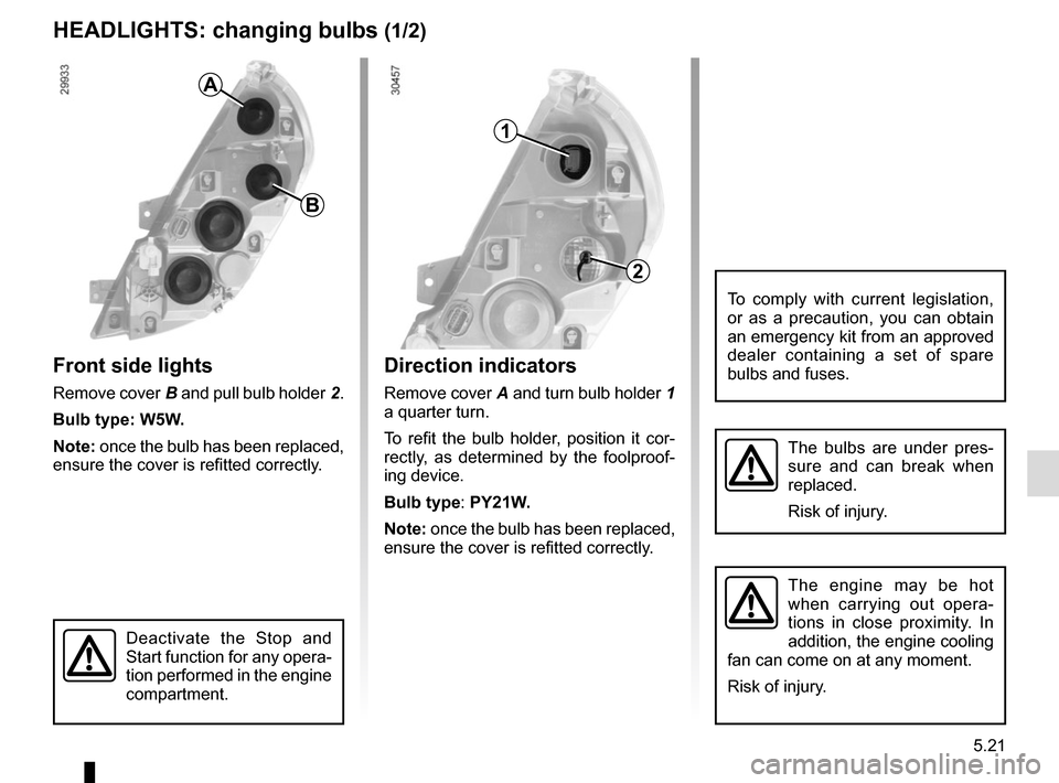
Direction indicators
Remove cover A and turn bulb holder 1
a quarter turn.
To refit the bulb holder, position it cor-
rectly, as determined by the foolproof-
ing device.
Bulb type: PY21W.
Note: once the bulb has been replaced,
ensure the cover is refitted correctly.
HEADLIGHTS: changing bulbs (1/2)
Front side lights
Remove cover B and pull bulb holder 2.
Bulb type: W5W.
Note: once the bulb has been replaced,
ensure the cover is refitted correctly.
The bulbs are under pres-
sure and can break when
replaced.
Risk of injury.
To comply with current legislation,
or as a precaution, you can obtain
an emergency kit from an approved
dealer containing a set of spare
bulbs and fuses.
B
A
2
1
The engine may be hot
when carrying out opera-
tions in close proximity. In
addition, the engine cooling
fan can come on at any moment.
Risk of injury.
Deactivate the Stop and
Start function for any opera-
tion performed in the engine
compartment.
Page 230 of 284
5.22
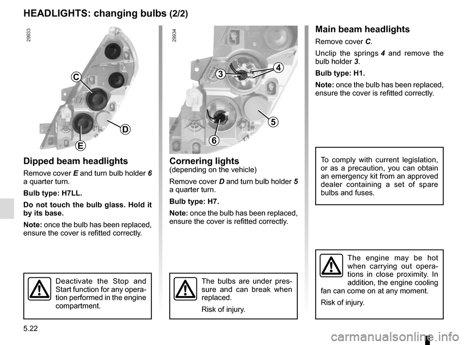
Dipped beam headlights
Remove cover E and turn bulb holder 6
a quarter turn.
Bulb type: H7LL.
Do not touch the bulb glass. Hold it
by its base.
Note: once the bulb has been replaced,
ensure the cover is refitted correctly.
Main beam headlights
Remove cover C.
Unclip the springs 4 and remove the
bulb holder 3.
Bulb type: H1.
Note: once the bulb has been replaced,
ensure the cover is refitted correctly.
The bulbs are under pres-
sure and can break when
replaced.
Risk of injury.
To comply with current legislation,
or as a precaution, you can obtain
an emergency kit from an approved
dealer containing a set of spare
bulbs and fuses.
HEADLIGHTS: changing bulbs (2/2)
Cornering lights
(depending on the vehicle)
Remove cover D and turn bulb holder 5
a quarter turn.
Bulb type: H7.
Note: once the bulb has been replaced,
ensure the cover is refitted correctly.
C
D
E
3
5
6
4
The engine may be hot
when carrying out opera-
tions in close proximity. In
addition, the engine cooling
fan can come on at any moment.
Risk of injury.
Deactivate the Stop and
Start function for any opera-
tion performed in the engine
compartment.