check engine RENAULT MASTER 2016 X62 / 2.G Owner's Manual
[x] Cancel search | Manufacturer: RENAULT, Model Year: 2016, Model line: MASTER, Model: RENAULT MASTER 2016 X62 / 2.GPages: 284, PDF Size: 6.69 MB
Page 193 of 284
4.3
BONNET (2/2)
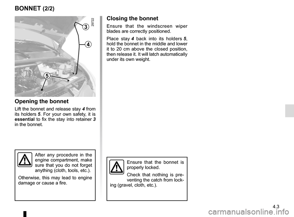
3
4
5
Closing the bonnet
Ensure that the windscreen wiper
blades are correctly positioned.
Place stay 4 back into its holders 5,
hold the bonnet in the middle and lower
it to 20 cm above the closed position,
then release it. It will latch automatically
under its own weight.
Ensure that the bonnet is
properly locked.
Check that nothing is pre-
venting the catch from lock-
ing (gravel, cloth, etc.).
Opening the bonnet
Lift the bonnet and release stay 4 from
its holders 5. For your own safety, it is
essential to fix the stay into retainer 3
in the bonnet.
After any procedure in the
engine compartment, make
sure that you do not forget
anything (cloth, tools, etc.).
Otherwise, this may lead to engine
damage or cause a fire.
Page 194 of 284
4.4
ENGINE OIL LEVEL: general information (1/2)
If the level is at the minimum
The “TOP-UP OIL LEVEL” message
and warning light
© are displayed
on the instrument panel.
It is vital to top up the oil as soon as
possible.
The display only warns the
driver if the oil level is at the
minimum level. It does not
inform the driver that the oil
level has exceeded the maximum
level as this can only be measured
using a dipstick.
It is normal for an engine to use oil for
lubrication and cooling of moving parts
and it is normal to top up the level be-
tween oil changes.
However, contact an approved Dealer
if more than 0.5 litres is being consu-
med every 600 miles (1,000 km) after
the running in period.
Oil change frequency: check the oil
level from time to time and certainly
before any long journey to avoid the
risk of damaging your engine.
Reading the oil level
The oil level should be read with the
vehicle on level ground, after the engine
has been switched off for some time.
The dipstick must be used to read
the exact oil level and make sure
that the maximum level has not been
exceeded (risk of engine damage).
Refer to the following pages.
The instrument panel display only
alerts the driver when the oil level is at
its minimum.
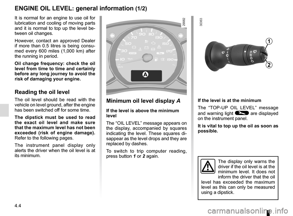
A
1
2
Minimum oil level display A
If the level is above the minimum
level
The “OIL LEVEL” message appears on
the display, accompanied by squares
indicating the level. These squares di-
sappear as the level drops and they are
replaced by dashes.
To switch to trip computer reading,
press button 1 or 2 again.
Page 196 of 284
4.6
Topping up/filling
The vehicle must be parked on level
ground and the engine should be cold
(for instance, before the engine is
started up for the first time in the day).
Engine oil grade
Refer to the Maintenance Document for
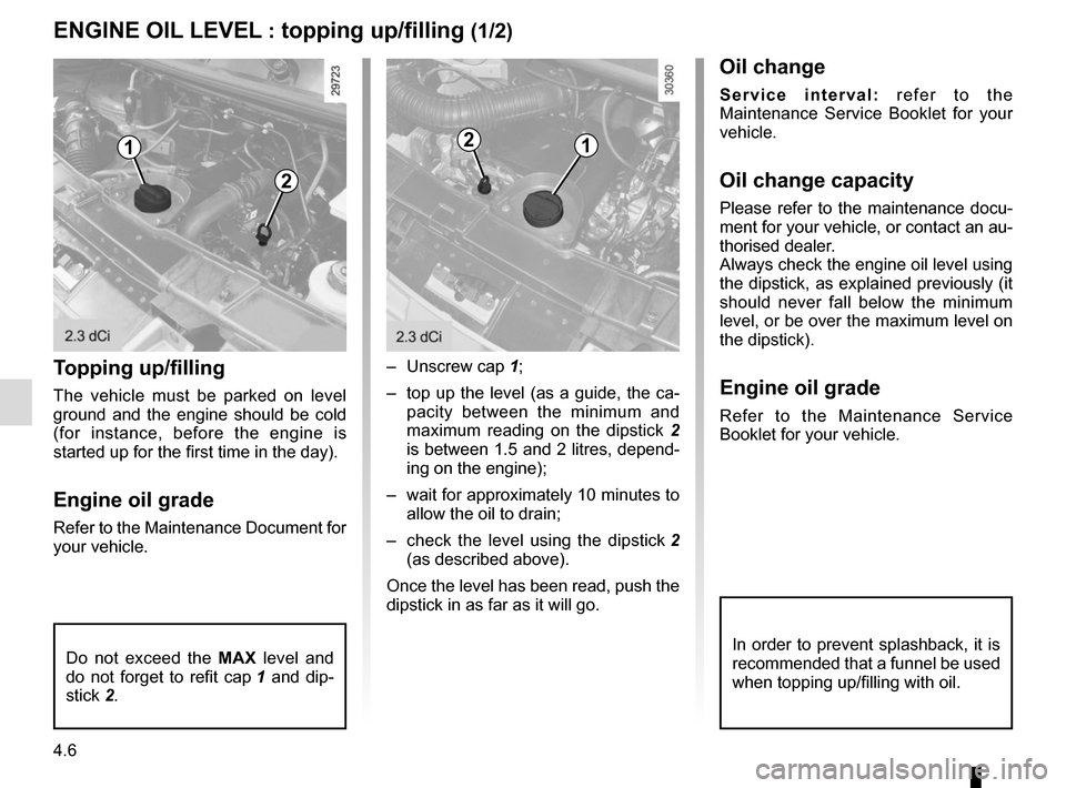
your vehicle.– Unscrew cap
1;
– top up the level (as a guide, the ca- pacity between the minimum and
maximum reading on the dipstick 2
is between 1.5 and 2 litres, depend-
ing on the engine);
– wait for approximately 10 minutes to allow the oil to drain;
– check the level using the dipstick 2
(as described above).
Once the level has been read, push the
dipstick in as far as it will go.
Do not exceed the MAX level and
do not forget to refit cap 1 and dip-
stick 2.
ENGINE OIL LEVEL : topping up/filling (1/2)
In order to prevent splashback, it is
recommended that a funnel be used
when topping up/filling with oil.
1
2
12
Oil change
Service interval: refer to the
Maintenance Service Booklet for your
vehicle.
Oil change capacity
Please refer to the maintenance docu-
ment for your vehicle, or contact an au-
thorised dealer.
Always check the engine oil level using
the dipstick, as explained previously (it
should never fall below the minimum
level, or be over the maximum level on
the dipstick).
Engine oil grade
Refer to the Maintenance Service
Booklet for your vehicle.
Page 198 of 284
4.8
LEVELS (1/3)
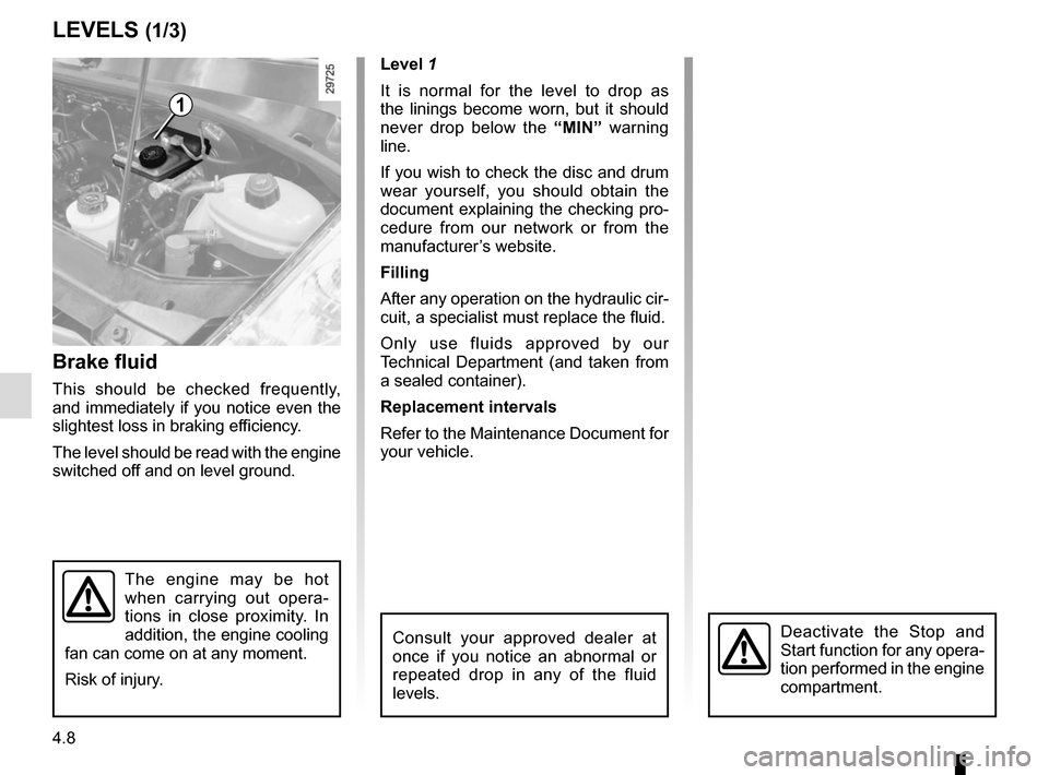
Brake fluid
This should be checked frequently,
and immediately if you notice even the
slightest loss in braking efficiency.
The level should be read with the engine
switched off and on level ground. Level 1
It is normal for the level to drop as
the linings become worn, but it should
never drop below the
“MIN” warning
line.
If you wish to check the disc and drum
wear yourself, you should obtain the
document explaining the checking pro-
cedure from our network or from the
manufacturer’s website.
Filling
After any operation on the hydraulic cir-
cuit, a specialist must replace the fluid.
Only use fluids approved by our
Technical Department (and taken from
a sealed container).
Replacement intervals
Refer to the Maintenance Document for
your vehicle.
Consult your approved dealer at
once if you notice an abnormal or
repeated drop in any of the fluid
levels.
1
The engine may be hot
when carrying out opera-
tions in close proximity. In
addition, the engine cooling
fan can come on at any moment.
Risk of injury.
Deactivate the Stop and
Start function for any opera-
tion performed in the engine
compartment.
Page 199 of 284
4.9
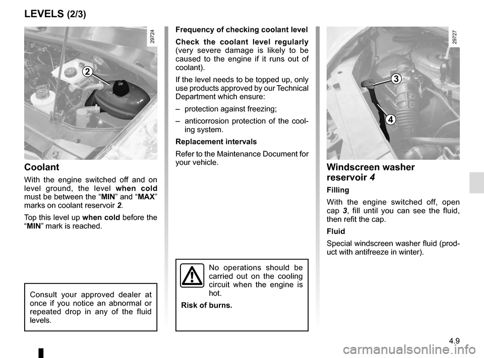
Coolant
With the engine switched off and on
level ground, the level when cold
must be between the “MIN” and “MAX”
marks on coolant reservoir 2.
Top this level up when cold before the
“MIN” mark is reached.
LEVELS (2/3)
Frequency of checking coolant level
Check the coolant level regularly
(very severe damage is likely to be
caused to the engine if it runs out of
coolant).
If the level needs to be topped up, only
use products approved by our Technical
Department which ensure:
– protection against freezing;
– anticorrosion protection of the cool- ing system.
Replacement intervals
Refer to the Maintenance Document for
your vehicle.
2
Windscreen washer
reservoir 4
Filling
With the engine switched off, open
cap 3, fill until you can see the fluid,
then refit the cap.
Fluid
Special windscreen washer fluid (prod-
uct with antifreeze in winter).
3
4
Consult your approved dealer at
once if you notice an abnormal or
repeated drop in any of the fluid
levels.
No operations should be
carried out on the cooling
circuit when the engine is
hot.
Risk of burns.
Page 203 of 284
4.13
When the ignition is off, some consu-
mers may also be switched off (dipped
beam headlights, radio, ventilation,
etc.). On the instrument panel, the mes-
sage “BATTERY MODE: ECONOMY”
appears when switched off. When the
level is extremely low, the message
“BATTERY LOW START ENGINE” is
displayed.
The charge status of the battery can
decrease, especially if you use your
vehicle:
– for short journeys;
– for driving in town;
– when the temperature drops;
– with the vehicle stopped and the engine off.
Replacing the battery
As this operation is complex, we advise
you to contact an approved Dealer.
BATTERY
123
456
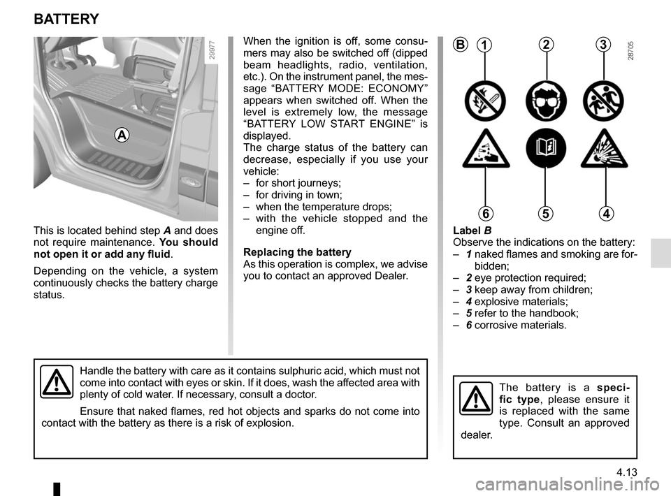
This is located behind step A and does
not require maintenance. You should
not open it or add any fluid .
Depending on the vehicle, a system
continuously checks the battery charge
status.
Handle the battery with care as it contains sulphuric acid, which must n\
ot
come into contact with eyes or skin. If it does, wash the affected area with
plenty of cold water. If necessary, consult a doctor.
Ensure that naked flames, red hot objects and sparks do not come into
contact with the battery as there is a risk of explosion.
Label B
Observe the indications on the battery:
– 1 naked flames and smoking are for-
bidden;
– 2 eye protection required;
– 3 keep away from children;
– 4 explosive materials;
– 5 refer to the handbook;
– 6 corrosive materials.
The battery is a speci-
fic type, please ensure it
is replaced with the same
type. Consult an approved
dealer.
B
A
Page 215 of 284
5.7
TYRE INFLATION KIT (3/6)
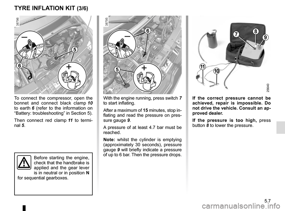
To connect the compressor, open the
bonnet and connect black clamp 10
to earth 6 (refer to the information on
“Battery: troubleshooting” in Section 5).
Then connect red clamp 11 to termi-
nal 5.
Before starting the engine,
check that the handbrake is
applied and the gear lever
is in neutral or in position N
for sequential gearboxes.
With the engine running, press switch 7
to start inflating.
After a maximum of 15 minutes, stop in-
flating and read the pressure on pres-
sure gauge 9.
A pressure of at least 4.7 bar must be
reached.
Note: whilst the cylinder is emptying
(approximately 30 seconds), pressure
gauge 9 will briefly indicate a pressure
of up to 6 bar. Then the pressure drops.
1110
7
If the correct pressure cannot be
achieved, repair is impossible. Do
not drive the vehicle. Consult an ap-
proved dealer.
If the pressure is too high, press
button 8 to lower the pressure.
8
9
5
6
6
5
Page 236 of 284
5.28
FUSES (1/5)
1
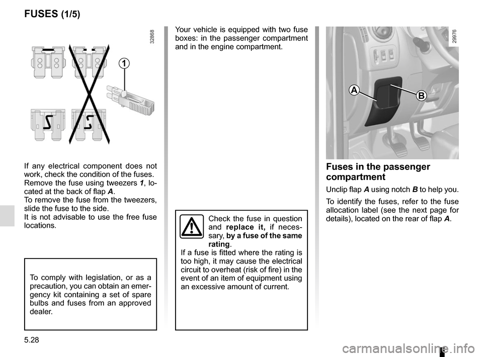
If any electrical component does not
work, check the condition of the fuses.
Remove the fuse using tweezers 1, lo-
cated at the back of flap A.
To remove the fuse from the tweezers,
slide the fuse to the side.
It is not advisable to use the free fuse
locations.
To comply with legislation, or as a
precaution, you can obtain an emer-
gency kit containing a set of spare
bulbs and fuses from an approved
dealer.
Your vehicle is equipped with two fuse
boxes: in the passenger compartment
and in the engine compartment.
A
Fuses in the passenger
compartment
Unclip flap A using notch B to help you.
To identify the fuses, refer to the fuse
allocation label (see the next page for
details), located on the rear of flap A.
B
Check the fuse in question
and replace it, if neces-
sary, by a fuse of the same
rating.
If a fuse is fitted where the rating is
too high, it may cause the electrical
circuit to overheat (risk of fire) in the
event of an item of equipment using
an excessive amount of current.
Page 238 of 284
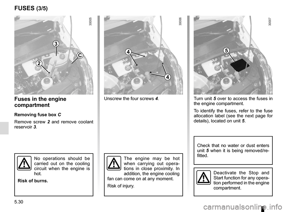
5.30
Fuses in the engine
compartment
Removing fuse box C
Remove screw 2 and remove coolant
reservoir 3. Unscrew the four screws
4.Turn unit 5 over to access the fuses in
the engine compartment.
To identify the fuses, refer to the fuse
allocation label (see the next page for
details), located on unit 5.
FUSES (3/5)
2
3
C4
4
5
The engine may be hot
when carrying out opera-
tions in close proximity. In
addition, the engine cooling
fan can come on at any moment.
Risk of injury.No operations should be
carried out on the cooling
circuit when the engine is
hot.
Risk of burns.
Check that no water or dust enters
unit 5 when it is being removed/re-
fitted.
Deactivate the Stop and
Start function for any opera-
tion performed in the engine
compartment.
Page 242 of 284

5.34
BATTERY: troubleshooting (2/2)
Attach the positive lead (+) A to termi-
nal 3, then to terminal 2 (+) of the bat-
tery supplying the current.
Attach negative lead (–) B to terminal 1
(–) of the battery supplying the current,
then to earth 4 (–).
Start the engine as normal. As soon as
it is running, disconnect leads A and B
in the reverse order ( 4-3-2-1).
Starting the vehicle using the
battery from another vehicle
If you have to use the battery from an-
other vehicle to start, obtain suitable
jump leads (with a large cross section)
from an approved dealer or, if you al-
ready have jump leads, ensure that
they are in perfect condition.
The two batteries must have an iden-
tical nominal voltage of 12 volts. The
battery supplying the current should
have a capacity (amp-hours, Ah) which
is at least the same as that of the dis-
charged battery.
Ensure that there is no risk of contact
between the two vehicles (risk of short
circuiting when the positive terminals
are connected). Switch off your vehicle
ignition.
Start the engine of the vehicle supply-
ing the current and run it at a moderate
speed.
A
B
21
Check that there is no contact between leads A and B and that the posi-
tive lead A is not touching any metal parts on the vehicle supplying the
current.
Risk of injury and/or damage to the vehicle.
3
4
4
3