tow RENAULT MASTER 2018 User Guide
[x] Cancel search | Manufacturer: RENAULT, Model Year: 2018, Model line: MASTER, Model: RENAULT MASTER 2018Pages: 290, PDF Size: 7.1 MB
Page 134 of 290
2.18
DRIVING CORRECTION DEVICES AND AIDS (3/8)
Emergency brake assist
This system supplements the ABS
and helps reduce vehicle stopping dis-
tances.
Operating principle
The system is for detecting an emer-
gency braking situation. In this case,
the braking assistance immediately de-
velops maximum power and may trig-
ger ABS regulation.
ABS braking is maintained as long as
the brake pedal is applied.
Hazard warning lights switching on
Depending on the vehicle, these may
light up in the event of sudden decel-
eration.
Operating faults
When the system detects an operat-
ing fault the message “CHECK ABS”
appears on the instrument panel along
with the
© warning light.
Consult an approved dealer.
Driver assistance with a
trailer
This system helps to maintain control
over the vehicle while using a trailer.
It detects shaking caused by towing a
trailer under certain driving conditions.
Operating conditions
– The towbar must be approved by an authorised dealer;
– the harness must be approved by an authorised dealer;
– the towbar must be connected to the vehicle.
Operating principle
The function stabilises the vehicle by:
– asymmetric braking of the front wheels to reduce shaking caused by
the trailer;
– braking of all four wheels and limita- tion on engine torque to reduce the
vehicle speed until the shaking has
stopped.
Warning light
flashes on the in-
strument panel to inform the driver.
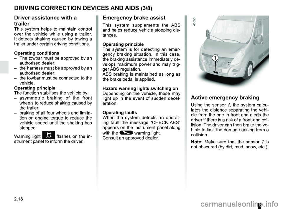
Active emergency braking
Using the sensor 1, the system calcu-
lates the distance separating the vehi-
cle from the one in front and alerts the
driver if there is a risk of a front-end col-
lision. The driver can then brake the ve-
hicle to limit the damage arising from a
collision.
Note: Make sure that the sensor 1 is
not obscured (by dirt, mud, snow, etc.).
1
Page 137 of 290
2.21
DRIVER CORRECTION DEVICES AND AIDS (6/8)
Active emergency braking
Limitation of the system operation
– A vehicle travelling in the opposite direction will not trigger any alert\
or any action on the system operation.
– The sensor area should be kept clean and free of any modifications in or\
der to ensure the proper operation of the system.
– The system cannot respond to small vehicles such as motorbikes or bicycl\
es as effectively as to other vehicles.
Deactivating the function
You must disable the function if:
– the brake lights are not functioning;
– the front of the vehicle has undergone an impact or been damaged;
– the vehicle is being towed (breakdowns).
Halting the function
You can halt the active braking function at any time by tapping the accel\
erator pedal or by turning the steering wheel in an
avoidance manoeuvre.
In the event of the system behaving abnormally, deactivate it and consult an authorised dealer.
Page 154 of 290
2.38
PARKING DISTANCE CONTROL (1/2)
This function is an addi-
tional aid that indicates the
distance between the vehi-
cle and an obstacle whilst
reversing, using sound signals.
Under no circumstances should it
replace the driver’s care or respon-
sibility whilst reversing.
The driver should always be ready
for sudden incidents while driv-
ing: always ensure that there are
no small, narrow moving obstacles
(such as a child, animal, pushchair,
bicycle, stone, post, etc.) in the blind
spot when manoeuvring.
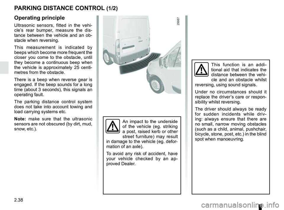
Operating principle
Ultrasonic sensors, fitted in the vehi-
cle’s rear bumper, measure the dis-
tance between the vehicle and an ob-
stacle when reversing.
This measurement is indicated by
beeps which become more frequent the
closer you come to the obstacle, until
they become a continuous beep when
the vehicle is approximately 25 centi-
metres from the obstacle.
There is a beep when reverse gear is
engaged. If the beep sounds for a long
time (about 3 seconds), this signals an
operating fault.
The parking distance control system
does not take into account towing and
load carrying systems etc.
Note: make sure that the ultrasonic
sensors are not obscured (by dirt, mud,
snow, etc.).
An impact to the underside
of the vehicle (eg. striking
a post, raised kerb or other
street furniture) may result
in damage to the vehicle (eg. defor-
mation of an axle).
To avoid any risk of accident, have
your vehicle checked by an ap-
proved Dealer.
Page 162 of 290
2.46
Reverse gear (vehicle stationary)
– Brake pedal depressed. Push the
selector lever towards the right and
to the rear as shown on the base
of the lever, and then release it.
Reverse gear is engaged and the
letter R appears on the display.
– Release the brake pedal: – the engine’s idle speed is suffi-
cient for parking manoeuvres;
– accelerate gently to reverse.
You may shift from reverse gear to a
forwards gear by pushing the lever for-
wards once the vehicle is stationary.
Note: When the vehicle is stationary,
you must depress the brake pedal to
engage or disengage a gear. Otherwise,
warning light 5 will come on.
SEQUENTIAL GEARBOX (2/5)
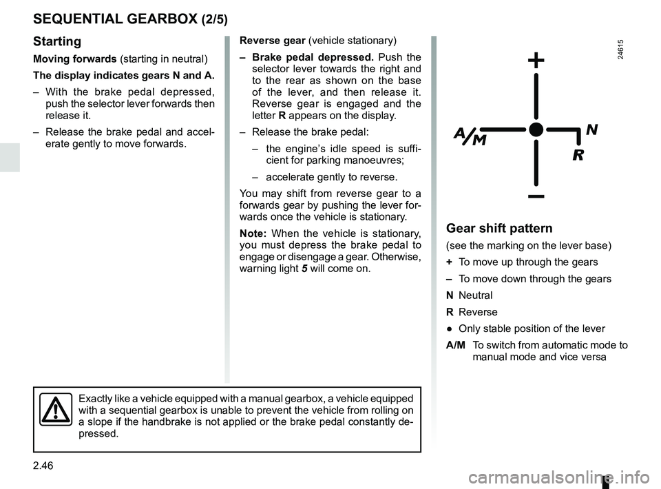
Gear shift pattern
(see the marking on the lever base)
+ To move up through the gears
– To move down through the gears
N Neutral
R Reverse
● Only stable position of the lever
A/M To switch from automatic mode to
manual mode and vice versa
24615
Exactly like a vehicle equipped with a manual gearbox, a vehicle equippe\
d
with a sequential gearbox is unable to prevent the vehicle from rolling \
on
a slope if the handbrake is not applied or the brake pedal constantly de\
-
pressed.
Starting
Moving forwards (starting in neutral)
The display indicates gears N and A.
– With the brake pedal depressed, push the selector lever forwards then
release it.
– Release the brake pedal and accel- erate gently to move forwards.
Page 165 of 290
2.49
SEQUENTIAL GEARBOX (5/5)
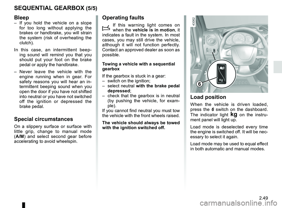
Load position
When the vehicle is driven loaded,
press the 6 switch on the dashboard.
The indicator light
§ on the instru-
ment panel will light up.
Load mode is deselected every time
the engine is switched off. It will be nec-
essary to select it again.
Load mode may be used to equal effect
in both automatic and manual modes.
6
Bleep– If you hold the vehicle on a slope for too long without applying the
brakes or handbrake, you will strain
the system (risk of overheating the
clutch).
In this case, an intermittent beep- ing sound will remind you that you
should put your foot on the brake
pedal or apply the handbrake.
– Never leave the vehicle with the engine running when in gear. For
safety reasons you will hear an in-
termittent beeping sound when you
open the door if you have not shifted
into neutral or you have not switched
off the ignition or depressed the
brake pedal.
Special circumstances
On a slippery surface or surface with
little grip, change to manual mode
(A/M) and select second gear before
accelerating to avoid wheelspin.
Operating faults
i
If this warning light comes on
when the vehicle is in motion , it
indicates a fault in the system. In most
cases, you may still drive the vehicle,
although it will not function perfectly.
Contact an approved dealer as soon as
possible.
Towing a vehicle with a sequential
gearbox
If the gearbox is stuck in a gear:
– switch on the ignition;
– select neutral with the brake pedal
depressed;
– check that the gearbox is in neutral (by pushing the vehicle, for exam-
ple).
If you cannot find neutral you must tow
the vehicle with the front wheels raised.
The vehicle should always be towed
with the ignition switched off.
Page 170 of 290
3.4
MANUAL AIR CONDITIONING, HEATING SYSTEM (1/3)
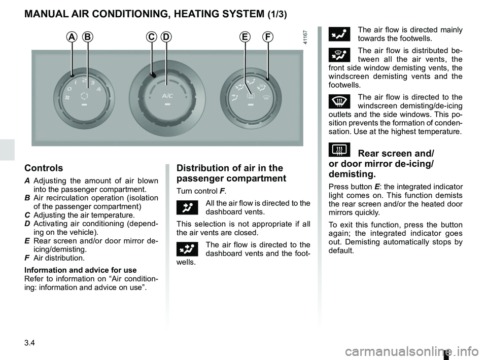
Controls
A Adjusting the amount of air blown into the passenger compartment.
B Air recirculation operation (isolation of the passenger compartment)
C Adjusting the air temperature.
D Activating air conditioning (depend- ing on the vehicle).
E Rear screen and/or door mirror de- icing/demisting.
F Air distribution.
Information and advice for use
Refer to information on “Air condition-
ing: information and advice on use”.
Distribution of air in the
passenger compartment
Turn control F.
JAll the air flow is directed to the
dashboard vents.
This selection is not appropriate if all
the air vents are closed.
GThe air flow is directed to the
dashboard vents and the foot-
wells.
FThe air flow is directed mainly
towards the footwells.
iThe air flow is distributed be-
tween all the air vents, the
front side window demisting vents, the
windscreen demisting vents and the
footwells.
WThe air flow is directed to the
windscreen demisting/de-icing
outlets and the side windows. This po-
sition prevents the formation of conden-
sation. Use at the highest temperature.
VRear screen and/
or door mirror de-icing/
demisting.
Press button E: the integrated indicator
light comes on. This function demists
the rear screen and/or the heated door
mirrors quickly.
To exit this function, press the button
again; the integrated indicator goes
out. Demisting automatically stops by
default.
ABDFCE
Page 176 of 290
3.10
ôThe air flow is directed mainly
to the dashboard air vents.
öThe air flow is directed towards
all the air vents and the pas-
senger footwells.
FThe air flow is directed mainly
towards the footwells.
The manual air distribution option
causes the operating tell-tale light
on display 4 to go out (automatic
mode), but only air distribution is no
longer controlled automatically by
the system.
Press button 3 to return to auto-
matic mode.
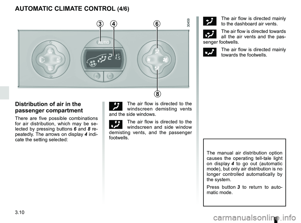
Distribution of air in the
passenger compartment
There are five possible combinations
for air distribution, which may be se-
lected by pressing buttons 6 and 8 re-
peatedly. The arrows on display 4 indi-
cate the setting selected:
õThe air flow is directed to the
windscreen demisting vents
and the side windows.
÷The air flow is directed to the
windscreen and side window
demisting vents, and the passenger
footwells.
AUTOMATIC CLIMATE CONTROL (4/6)
346
8
Page 179 of 290
3.13
Operating faults
As a general rule, contact your ap-
proved dealer in the event of an oper-
ating fault.
– Reduction in de-icing, demisting or air conditioning performance.
This may be caused by the passen-
ger compartment filter cartridge be-
coming clogged.
– No cold air is being produced .
Check that the controls are set cor-
rectly and that the fuses are sound.
Otherwise, switch off the system.
Presence of water under the
vehicle
After prolonged use of the air condi-
tioning system, it is normal for water
to be present under the vehicle. This is
caused by condensation.
AIR CONDITIONING: information and operating instructions (1/2)
Do not open the refriger-
ant fluid circuit. The fluid
may damage eyes or skin.
Fuel consumption
You will normally notice an increase in
fuel consumption (especially in town)
when the air conditioning is operating.
For vehicles fitted with air conditioning
with no automatic mode, switch off the
system when it is not required.
Advice for reducing consumption
and helping to preserve the environ-
ment
Drive with the air vents open and the
windows closed.
If the vehicle has been parked in the
sun, open the doors for a few moments
to let the hot air escape before starting
the engine.
Maintenance
Refer to the Maintenance Document
for your vehicle for the inspection fre-
quency.
Advice on use
In some situations (air conditioning off,
air recirculation activated, ventilation
speed at zero or low etc.), you may
notice that condensation starts to form
on the windows and windscreen.
If there is condensation, use the “Clear
View” function to remove it, then use
the air conditioning in automatic mode
to stop it forming again.
Do not add anything to the
vehicle’s ventilation circuit
(for example, to remove
bad odours).
There is a risk of damage or of
fire.
Use the air conditioning system reg-
ularly, even in cold weather, running
it at least once a month for approxi-
mately 5 minutes.
Vehicles equipped with
modeECO
Once activated, ECO mode may
reduce air conditioning perform-
ance. Please refer to the informa-
tion on “Driving advice, Eco-driving”
in Section 2.
Page 189 of 290

3.23
24
25
PASSENGER COMPARTMENT STORAGE, FITTINGS (4/6)
Tray 25
Pull tray 25 fully towards you.
Turn it and push it fully.
You can use clip 24 to attach A5 format
documents.
To refit it, pull the table tray fully to-
wards you, lift it up until it is horizontal
and push it in fully.
Upper cab storage
compartment 26 and 27
Reserved for the transport of objects
only.
The total weight of upper cab storage
compartment 27 must not exceed 5 kg.
Do not hang any heavy and/
or sharp objects which may
fall whilst driving. Risk of
injury.
Nothing should be placed
on the floor area in front of
the driver as such objects
may slide under the pedal
during braking manoeuvres, thus
obstructing its use.
26
27
Page 196 of 290
3.30
TRANSPORTING OBJECTS (2/2)
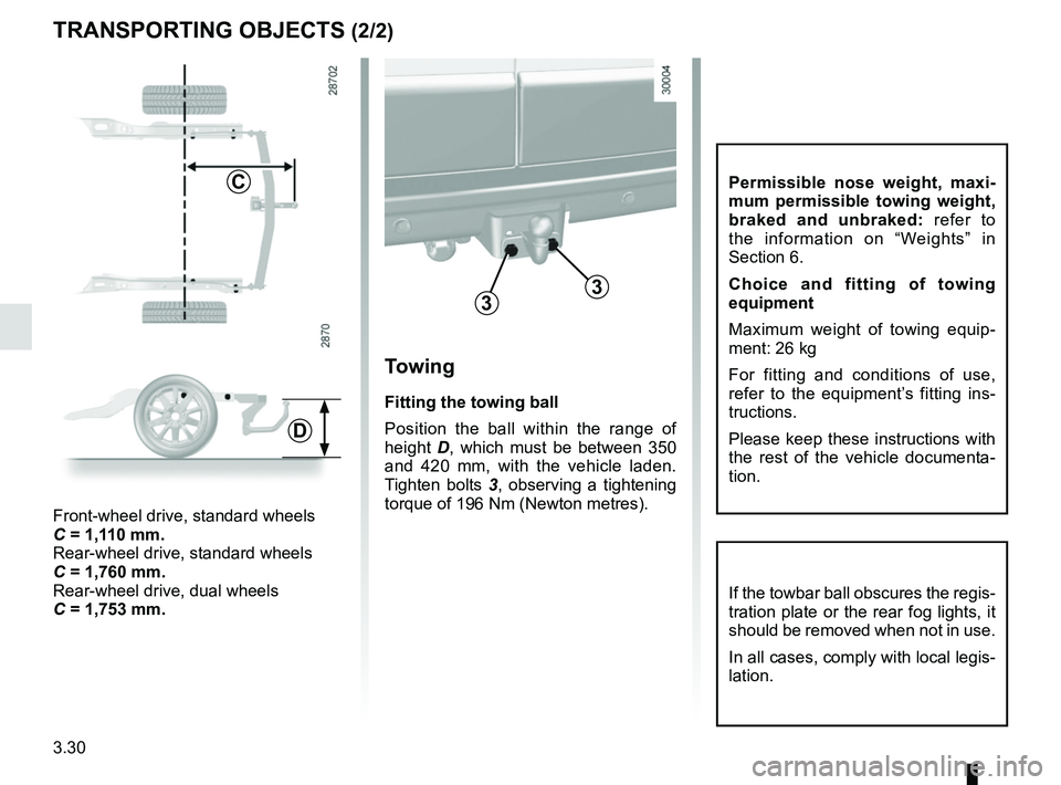
Towing
Fitting the towing ball
Position the ball within the range of
height D, which must be between 350
and 420 mm, with the vehicle laden.
Tighten bolts 3, observing a tightening
torque of 196 Nm (Newton metres).
33
C
Front-wheel drive, standard wheels
C = 1,110 mm.
Rear-wheel drive, standard wheels
C = 1,760 mm.
Rear-wheel drive, dual wheels
C = 1,753 mm.
D
If the towbar ball obscures the regis-
tration plate or the rear fog lights, it
should be removed when not in use.
In all cases, comply with local legis-
lation.
Permissible nose weight, maxi-
mum permissible towing weight,
braked and unbraked: refer to
the information on “Weights” in
Section 6.
Choice and fitting of towing
equipment
Maximum weight of towing equip-
ment: 26 kg
For fitting and conditions of use,
refer to the equipment’s fitting ins-
tructions.
Please keep these instructions with
the rest of the vehicle documenta-
tion.