towing RENAULT MASTER 2018 Owners Manual
[x] Cancel search | Manufacturer: RENAULT, Model Year: 2018, Model line: MASTER, Model: RENAULT MASTER 2018Pages: 290, PDF Size: 7.1 MB
Page 94 of 290
1.88
TRIP COMPUTER: journey parameters (3/4)
Examples of selectionsInterpreting the display selected
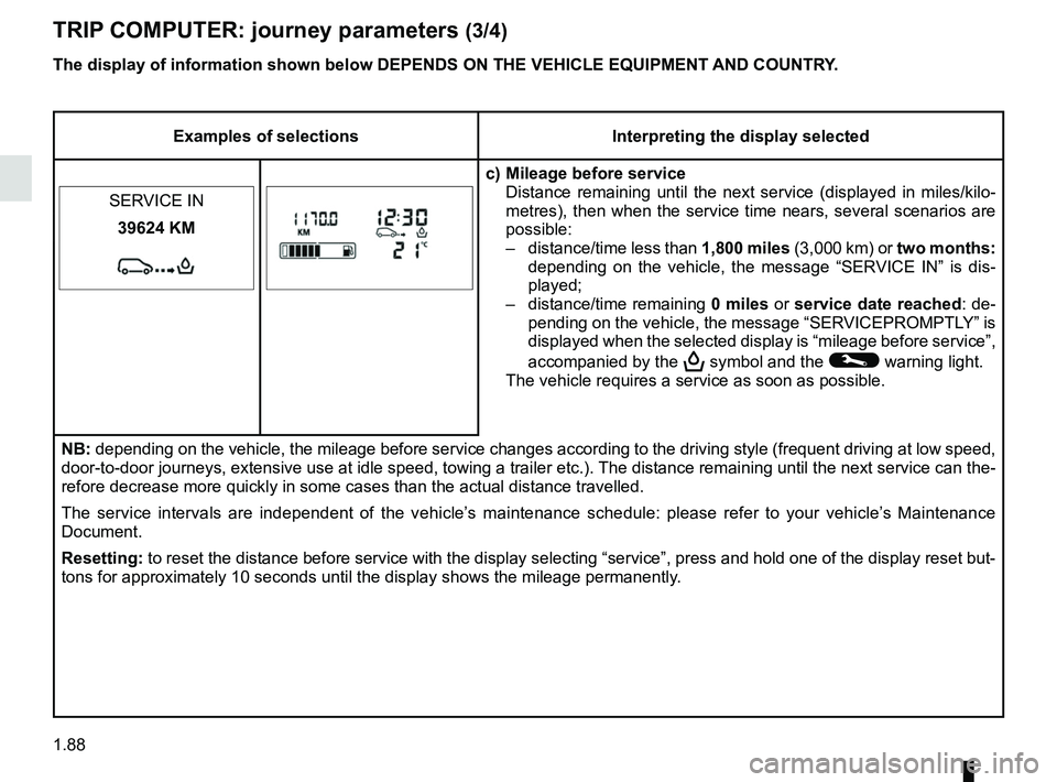
c) Mileage before service Distance remaining until the next service (displayed in miles/kilo-
metres), then when the service time nears, several scenarios are
possible:
– distance/time less than 1,800 miles (3,000 km) or two months:
depending on the vehicle, the message “SERVICE IN” is dis-
played;
– distance/time remaining 0 miles or service date reached : de-
pending on the vehicle, the message “SERVICEPROMPTLY” is
displayed when the selected display is “mileage before service”,
accompanied by the
9 symbol and the © warning light.
The vehicle requires a service as soon as possible.
SERVICE IN
39624 KM
NB: depending on the vehicle, the mileage before service changes according \
to the driving style (frequent driving at low speed,
door-to-door journeys, extensive use at idle speed, towing a trailer etc\
.). The distance remaining until the next service can t
he-
refore decrease more quickly in some cases than the actual distance trav\
elled.
The service intervals are independent of the vehicle’s maintenance schedule: please refer to your vehicle’s Maintenance
Document.
Resetting: to reset the distance before service with the display selecting “ser\
vice”, press and hold one of the display reset but-
tons for approximately 10 seconds until the display shows the mileage pe\
rmanently.
The display of information shown below DEPENDS ON THE VEHICLE EQUIPMENT \
AND COUNTRY.
Page 127 of 290
2.11
DRIVING ADVICE, ECO-DRIVING (4/4)
Advice on use
– Favour ECO mode.
– Electricity is fuel; switch off all the electrical components which are
not really needed. However (safety
first), keep your lights on when the
visibility is bad (“see and be seen”).
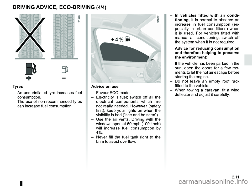
– Use the air vents. Driving with the windows open at 60 mph (100 km/h)
will increase fuel consumption by
4%.
– Never fill the fuel tank right to the brim to avoid overflow.
– In vehicles fitted with air condi-
tioning, it is normal to observe an
increase in fuel consumption (es-
pecially in urban conditions) when
it is used. For vehicles fitted with
manual air conditioning, switch off
the system when it is not required.
Advice for reducing consumption
and therefore helping to preserve
the environment:
If the vehicle has been parked in the
sun, open the doors for a few mo-
ments to let the hot air escape before
starting the engine.
– Do not leave an empty roof rack fitted to the vehicle.
– When towing a caravan, fit a wind deflector and adjust it carefully.
Tyres
– An underinflated tyre increases fuel consumption.
– The use of non-recommended tyres can increase fuel consumption.
Page 134 of 290
2.18
DRIVING CORRECTION DEVICES AND AIDS (3/8)
Emergency brake assist
This system supplements the ABS
and helps reduce vehicle stopping dis-
tances.
Operating principle
The system is for detecting an emer-
gency braking situation. In this case,
the braking assistance immediately de-
velops maximum power and may trig-
ger ABS regulation.
ABS braking is maintained as long as
the brake pedal is applied.
Hazard warning lights switching on
Depending on the vehicle, these may
light up in the event of sudden decel-
eration.
Operating faults
When the system detects an operat-
ing fault the message “CHECK ABS”
appears on the instrument panel along
with the
© warning light.
Consult an approved dealer.
Driver assistance with a
trailer
This system helps to maintain control
over the vehicle while using a trailer.
It detects shaking caused by towing a
trailer under certain driving conditions.
Operating conditions
– The towbar must be approved by an authorised dealer;
– the harness must be approved by an authorised dealer;
– the towbar must be connected to the vehicle.
Operating principle
The function stabilises the vehicle by:
– asymmetric braking of the front wheels to reduce shaking caused by
the trailer;
– braking of all four wheels and limita- tion on engine torque to reduce the
vehicle speed until the shaking has
stopped.
Warning light
flashes on the in-
strument panel to inform the driver.
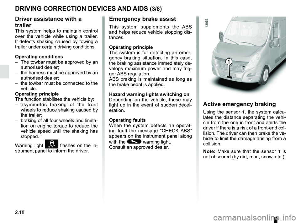
Active emergency braking
Using the sensor 1, the system calcu-
lates the distance separating the vehi-
cle from the one in front and alerts the
driver if there is a risk of a front-end col-
lision. The driver can then brake the ve-
hicle to limit the damage arising from a
collision.
Note: Make sure that the sensor 1 is
not obscured (by dirt, mud, snow, etc.).
1
Page 154 of 290
2.38
PARKING DISTANCE CONTROL (1/2)
This function is an addi-
tional aid that indicates the
distance between the vehi-
cle and an obstacle whilst
reversing, using sound signals.
Under no circumstances should it
replace the driver’s care or respon-
sibility whilst reversing.
The driver should always be ready
for sudden incidents while driv-
ing: always ensure that there are
no small, narrow moving obstacles
(such as a child, animal, pushchair,
bicycle, stone, post, etc.) in the blind
spot when manoeuvring.
Operating principle
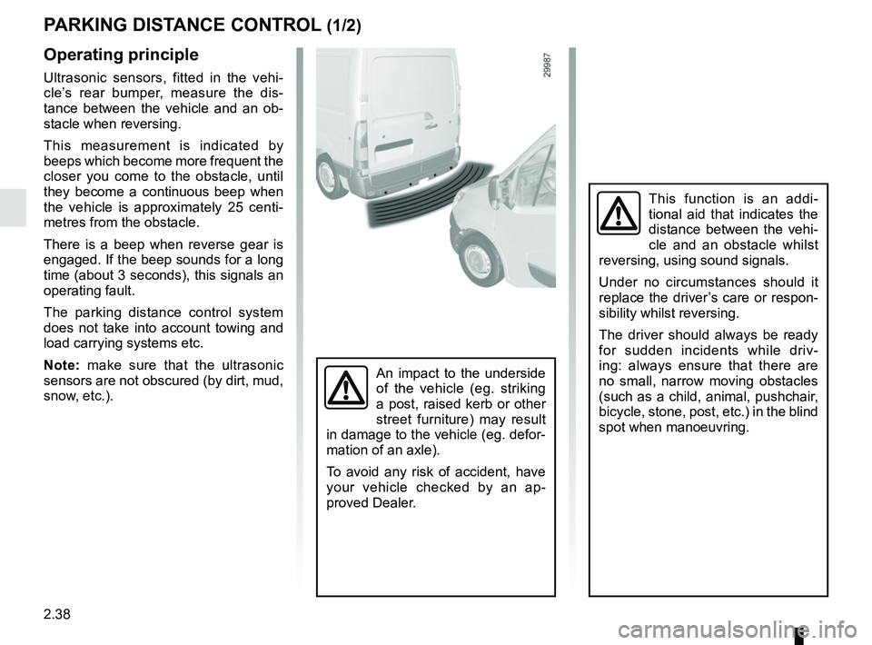
Ultrasonic sensors, fitted in the vehi-
cle’s rear bumper, measure the dis-
tance between the vehicle and an ob-
stacle when reversing.
This measurement is indicated by
beeps which become more frequent the
closer you come to the obstacle, until
they become a continuous beep when
the vehicle is approximately 25 centi-
metres from the obstacle.
There is a beep when reverse gear is
engaged. If the beep sounds for a long
time (about 3 seconds), this signals an
operating fault.
The parking distance control system
does not take into account towing and
load carrying systems etc.
Note: make sure that the ultrasonic
sensors are not obscured (by dirt, mud,
snow, etc.).
An impact to the underside
of the vehicle (eg. striking
a post, raised kerb or other
street furniture) may result
in damage to the vehicle (eg. defor-
mation of an axle).
To avoid any risk of accident, have
your vehicle checked by an ap-
proved Dealer.
Page 165 of 290
2.49
SEQUENTIAL GEARBOX (5/5)
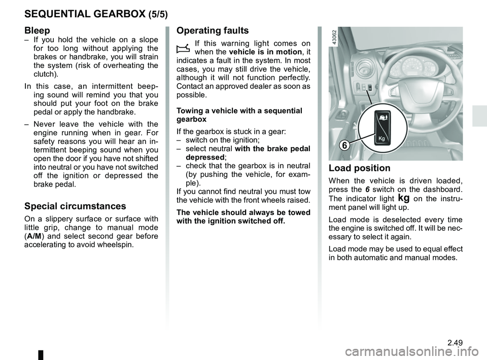
Load position
When the vehicle is driven loaded,
press the 6 switch on the dashboard.
The indicator light
§ on the instru-
ment panel will light up.
Load mode is deselected every time
the engine is switched off. It will be nec-
essary to select it again.
Load mode may be used to equal effect
in both automatic and manual modes.
6
Bleep– If you hold the vehicle on a slope for too long without applying the
brakes or handbrake, you will strain
the system (risk of overheating the
clutch).
In this case, an intermittent beep- ing sound will remind you that you
should put your foot on the brake
pedal or apply the handbrake.
– Never leave the vehicle with the engine running when in gear. For
safety reasons you will hear an in-
termittent beeping sound when you
open the door if you have not shifted
into neutral or you have not switched
off the ignition or depressed the
brake pedal.
Special circumstances
On a slippery surface or surface with
little grip, change to manual mode
(A/M) and select second gear before
accelerating to avoid wheelspin.
Operating faults
i
If this warning light comes on
when the vehicle is in motion , it
indicates a fault in the system. In most
cases, you may still drive the vehicle,
although it will not function perfectly.
Contact an approved dealer as soon as
possible.
Towing a vehicle with a sequential
gearbox
If the gearbox is stuck in a gear:
– switch on the ignition;
– select neutral with the brake pedal
depressed;
– check that the gearbox is in neutral (by pushing the vehicle, for exam-
ple).
If you cannot find neutral you must tow
the vehicle with the front wheels raised.
The vehicle should always be towed
with the ignition switched off.
Page 196 of 290
3.30
TRANSPORTING OBJECTS (2/2)
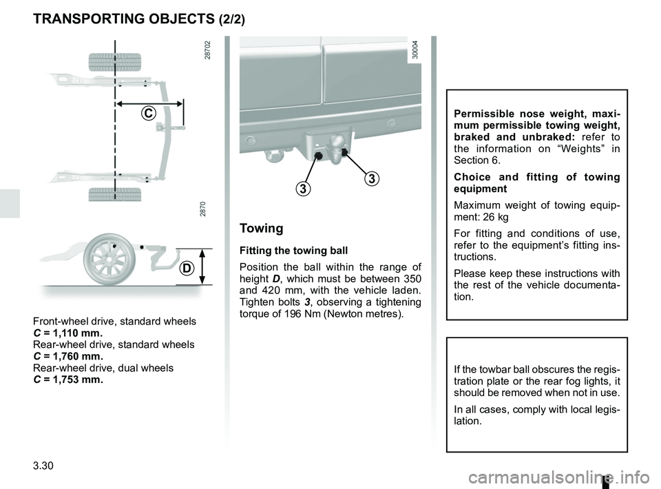
Towing
Fitting the towing ball
Position the ball within the range of
height D, which must be between 350
and 420 mm, with the vehicle laden.
Tighten bolts 3, observing a tightening
torque of 196 Nm (Newton metres).
33
C
Front-wheel drive, standard wheels
C = 1,110 mm.
Rear-wheel drive, standard wheels
C = 1,760 mm.
Rear-wheel drive, dual wheels
C = 1,753 mm.
D
If the towbar ball obscures the regis-
tration plate or the rear fog lights, it
should be removed when not in use.
In all cases, comply with local legis-
lation.
Permissible nose weight, maxi-
mum permissible towing weight,
braked and unbraked: refer to
the information on “Weights” in
Section 6.
Choice and fitting of towing
equipment
Maximum weight of towing equip-
ment: 26 kg
For fitting and conditions of use,
refer to the equipment’s fitting ins-
tructions.
Please keep these instructions with
the rest of the vehicle documenta-
tion.
Page 208 of 290
4.12
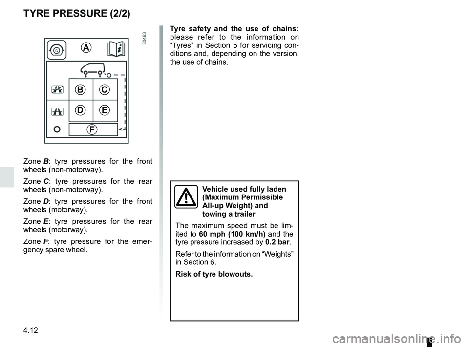
BC
ED
F
A
Zone B: tyre pressures for the front
wheels (non-motorway).
Zone C : tyre pressures for the rear
wheels (non-motorway).
Zone D : tyre pressures for the front
wheels (motorway).
Zone E : tyre pressures for the rear
wheels (motorway).
Zone F : tyre pressure for the emer-
gency spare wheel.
TYRE PRESSURE (2/2)
Tyre safety and the use of chains:
please refer to the information on
“Tyres” in Section 5 for servicing con-
ditions and, depending on the version,
the use of chains.
Vehicle used fully laden
(Maximum Permissible
All-up Weight) and
towing a trailer
The maximum speed must be lim-
ited to 60 mph (100 km/h) and the
tyre pressure increased by 0.2 bar.
Refer to the information on “Weights”
in Section 6.
Risk of tyre blowouts.
Page 215 of 290
5.1
Section 5: Practical advice
Puncture . . . . . . . . . . . . . . . . . . . . . . . . . . . . . . . . . . . .\
. . . . . . . . . . . . . . . . . . . . . . . . . . . . . . . . . . 5.2
Emergency spare wheel . . . . . . . . . . . . . . . . . . . . . . . . . . . . . . . . . . . .\
. . . . . . . . . . . . . . . . . . . . . . 5.2
Tool kit . . . . . . . . . . . . . . . . . . . . . . . . . . . . . . . . . . . . \
. . . . . . . . . . . . . . . . . . . . . . . . . . . . . . . . . . . . 5.4
Tyre inflation kit . . . . . . . . . . . . . . . . . . . . . . . . . . . . . . . . . . . .\
. . . . . . . . . . . . . . . . . . . . . . . . . . . . . 5.5
Wheel trims . . . . . . . . . . . . . . . . . . . . . . . . . . . . . . \
. . . . . . . . . . . . . . . . . . . . . . . . . . . . . . . . . . . . . . 5.11
Changing a wheel: hydraulic jack . . . . . . . . . . . . . . . . . . . . . . . . . . . . . . . . . . . .\
. . . . . . . . . . . . . . . 5.13
Changing a wheel: jack . . . . . . . . . . . . . . . . . . . . . . . . . . . . . . . . . . . . \
. . . . . . . . . . . . . . . . . . . . . . . 5.16
Tyres . . . . . . . . . . . . . . . . . . . . . . . . . . . . . . . . . . . .\
. . . . . . . . . . . . . . . . . . . . . . . . . . . . . . . . . . . . . 5.18
Headlights (changing bulbs) . . . . . . . . . . . . . . . . . . . . . . . . . . . . . . . . . . . .\
. . . . . . . . . . . . . . . . . . . 5.21front fog lights . . . . . . . . . . . . . . . . . . . . . . . . . . . . . . . . . . . . \
. . . . . . . . . . . . . . . . . . . . . . . . . 5.23
side lights . . . . . . . . . . . . . . . . . . . . . . . . . . . . . . . . . . . . \
. . . . . . . . . . . . . . . . . . . . . . . . . . . . 5.24
rear lights . . . . . . . . . . . . . . . . . . . . . . . . . . . . . . . . . . . . \
. . . . . . . . . . . . . . . . . . . . . . . . . . . . 5.25
interior lighting . . . . . . . . . . . . . . . . . . . . . . . . . . . . . . . . . . . .\
. . . . . . . . . . . . . . . . . . . . . . . . 5.27
Fuses . . . . . . . . . . . . . . . . . . . . . . . . . . . . . . . . . . . . \
. . . . . . . . . . . . . . . . . . . . . . . . . . . . . . . . . . . . . 5.28
Battery: troubleshooting. . . . . . . . . . . . . . . . . . . . . . . . . . . . . . . . . . . . \
. . . . . . . . . . . . . . . . . . . . . . . 5.33
Key, radio frequency remote control: battery . . . . . . . . . . . . . . . . . . . . . . . . . . . . . . . . . . . . \
. . . . . . . 5.35
Hands-free access transmitter/receiver: battery . . . . . . . . . . . . . . . . . . . . . . . . . . . . . . . . . . . .\
. . . . 5.36
Replacing wiper blades . . . . . . . . . . . . . . . . . . . . . . . . . . . . . . . . . . . . \
. . . . . . . . . . . . . . . . . . . . . . . 5.37
Towing . . . . . . . . . . . . . . . . . . . . . . . . . . . . . . . . . . . . \
. . . . . . . . . . . . . . . . . . . . . . . . . . . . . . . . . . . . 5.38
Fitting a radio . . . . . . . . . . . . . . . . . . . . . . . . . . . . . . . . . . . . \
. . . . . . . . . . . . . . . . . . . . . . . . . . . . . . . 5.40
Accessories . . . . . . . . . . . . . . . . . . . . . . . . . . . . . . . . . . . . \
. . . . . . . . . . . . . . . . . . . . . . . . . . . . . . . . 5.41
Operating faults . . . . . . . . . . . . . . . . . . . . . . . . . . . . . . . . . . . . \
. . . . . . . . . . . . . . . . . . . . . . . . . . . . . 5.42
Page 216 of 290
5.2
PUNCTURE, EMERGENCY SPARE WHEEL (1/2)
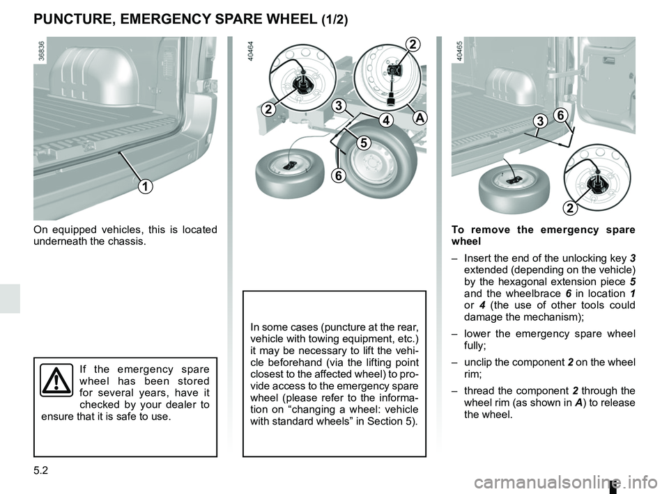
On equipped vehicles, this is located
underneath the chassis.
If the emergency spare
wheel has been stored
for several years, have it
checked by your dealer to
ensure that it is safe to use.
In some cases (puncture at the rear,
vehicle with towing equipment, etc.)
it may be necessary to lift the vehi-
cle beforehand (via the lifting point
closest to the affected wheel) to pro-
vide access to the emergency spare
wheel (please refer to the informa-
tion on “changing a wheel: vehicle
with standard wheels” in Section 5).
1
4
3
5
6
2
2
A
2
36
To remove the emergency spare
wheel
– Insert the end of the unlocking key 3
extended (depending on the vehicle)
by the hexagonal extension piece 5
and the wheelbrace 6 in location 1
or 4 (the use of other tools could
damage the mechanism);
– lower the emergency spare wheel fully;
– unclip the component 2 on the wheel
rim;
– thread the component 2 through the
wheel rim (as shown in A) to release
the wheel.
Page 218 of 290
5.4
TOOL KIT
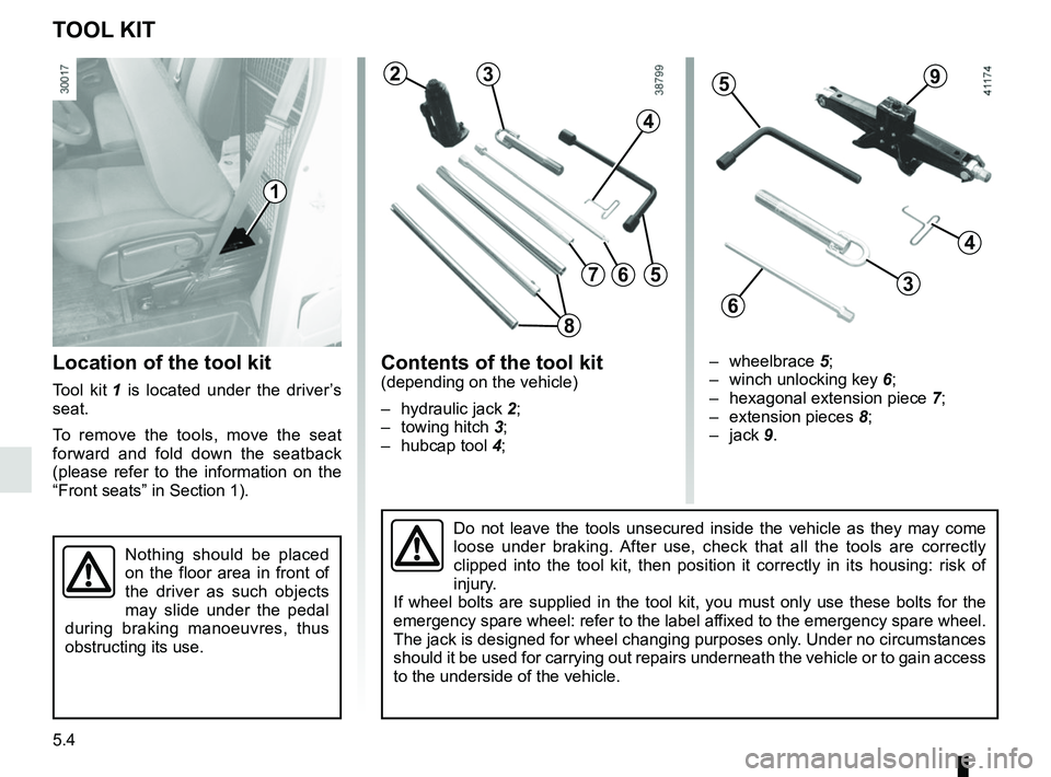
Location of the tool kit
Tool kit 1 is located under the driver’s
seat.
To remove the tools, move the seat
forward and fold down the seatback
(please refer to the information on the
“Front seats” in Section 1).
Contents of the tool kit(depending on the vehicle)
– hydraulic jack 2;
– towing hitch 3;
– hubcap tool 4;
1
Do not leave the tools unsecured inside the vehicle as they may come
loose under braking. After use, check that all the tools are correctly
clipped into the tool kit, then position it correctly in its housing: ri\
sk of
injury.
If wheel bolts are supplied in the tool kit, you must only use these bol\
ts for the
emergency spare wheel: refer to the label affixed to the emergency spare wheel.
The jack is designed for wheel changing purposes only. Under no circumstances
should it be used for carrying out repairs underneath the vehicle or to \
gain access
to the underside of the vehicle.
Nothing should be placed
on the floor area in front of
the driver as such objects
may slide under the pedal
during braking manoeuvres, thus
obstructing its use.
23
4
56
– wheelbrace 5;
– winch unlocking key 6;
– hexagonal extension piece 7;
– extension pieces 8;
– jack 9.
59
4
3
6
7
8