check engine light RENAULT MEGANE 2017 4.G User Guide
[x] Cancel search | Manufacturer: RENAULT, Model Year: 2017, Model line: MEGANE, Model: RENAULT MEGANE 2017 4.GPages: 346, PDF Size: 7.04 MB
Page 131 of 346
2.19
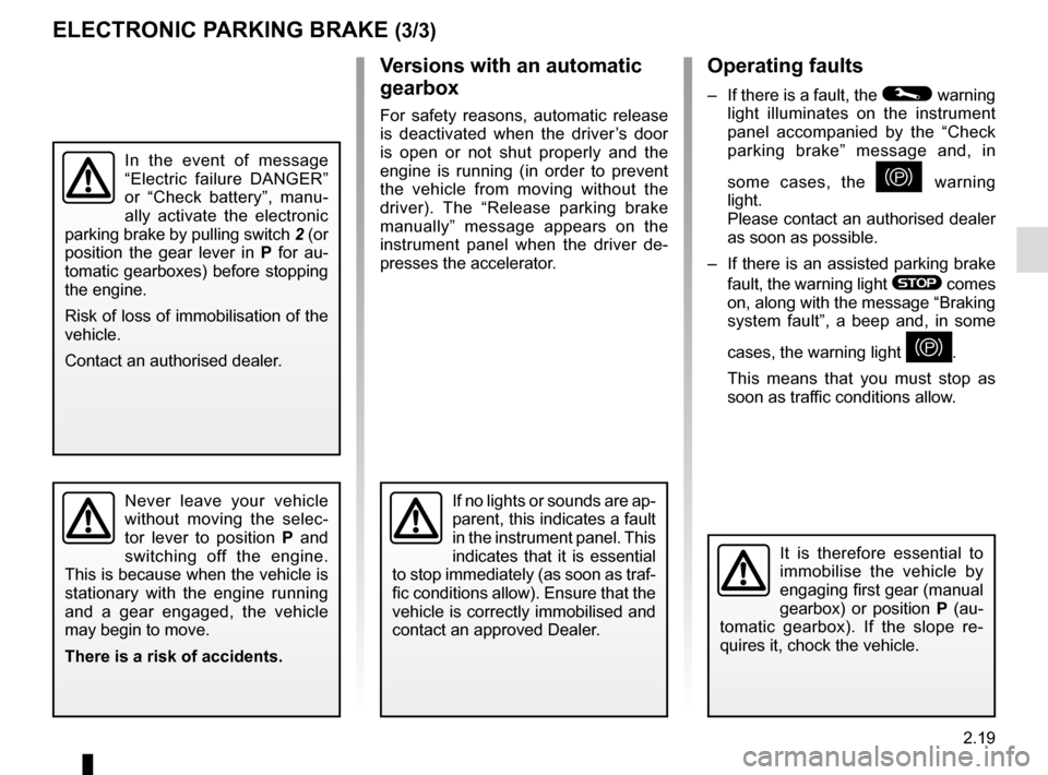
Operating faults
– If there is a fault, the © warning
light illuminates on the instrument
panel accompanied by the “Check
parking brake” message and, in
some cases, the
} warning
light.
Please contact an authorised dealer
as soon as possible.
– If there is an assisted parking brake fault, the warning light
® comes
on, along with the message “Braking
system fault”, a beep and, in some
cases, the warning light
}.
This means that you must stop as
soon as traffic conditions allow.
Versions with an automatic
gearbox
For safety reasons, automatic release
is deactivated when the driver’s door
is open or not shut properly and the
engine is running (in order to prevent
the vehicle from moving without the
driver). The “Release parking brake
manually” message appears on the
instrument panel when the driver de-
presses the accelerator.
ELECTRONIC PARKING BRAKE (3/3)
It is therefore essential to
immobilise the vehicle by
engaging first gear (manual
gearbox) or position P (au-
tomatic gearbox). If the slope re-
quires it, chock the vehicle.
Never leave your vehicle
without moving the selec-
tor lever to position P and
switching off the engine.
This is because when the vehicle is
stationary with the engine running
and a gear engaged, the vehicle
may begin to move.
There is a risk of accidents.If no lights or sounds are ap-
parent, this indicates a fault
in the instrument panel. This
indicates that it is essential
to stop immediately (as soon as traf-
fic conditions allow). Ensure that the
vehicle is correctly immobilised and
contact an approved Dealer.
In the event of message
“Electric failure DANGER”
or “Check battery”, manu-
ally activate the electronic
parking brake by pulling switch 2 (or
position the gear lever in P for au-
tomatic gearboxes) before stopping
the engine.
Risk of loss of immobilisation of the
vehicle.
Contact an authorised dealer.
Page 137 of 346
2.25
MAINTENANCE AND ANTIPOLLUTION ADVICE
Your vehicle complies with criteria for
recycling and recovering vehicles at the
end of their service life which will come
into force in 2015.
Some parts of your vehicle have there-
fore been designed to facilitate future
recycling.
These parts are easy to remove so
that they can be recovered and reproc-
essed by recycling companies.
By virtue of its design, moderate fuel
consumption and initial settings, your
vehicle also conforms to current anti-
pollution regulations. The manufac-
turer is actively striving to reduce pol-
lutant exhaust gas emissions and to
save energy. But the fuel consumption
of your vehicle and the level of pollutant
exhaust gas emissions are also your
responsibility. Ensure that it is main-
tained and used correctly.
Maintenance
It is important to remember that fail-
ure to respect antipollution regulations
could lead to legal action being taken
against the vehicle owner.In addition, replacing engine, fuel
supply system and exhaust compo-
nents with parts other than those origi-
nally recommended by the manufac-
turer may alter your vehicle so that it
no longer complies with anti-pollution
regulations.
Have your vehicle adjusted and
checked by an authorised dealer, in ac-
cordance with the instructions given in
your maintenance schedule: they will
have all the equipment necessary for
ensuring that your vehicle is maintained
to its original standard.
Engine adjustments
– Spark plugs:
for optimum condi-
tions of use, output and performance
the specifications laid down by our
Design Department must be strictly
applied.
If the spark plugs have to be changed, use the make, type and gap specified
for your vehicle’s engine. Contact an
authorised dealer for this.
– Air filter, fuel filter: a choked ele-
ment will reduce efficiency. It must
be replaced.
– Ignition and idle speed: no adjust-
ment is needed.
Exhaust gas monitoring
system
The exhaust gas monitoring system will
detect any operating faults in the vehi-
cle’s antipollution system.
If this system malfunctions, toxic sub-
stances may be released into the at-
mosphere or damage may occur.
ÄThis warning light on the in-
strument panel will indicate if
there are any faults in the system:
This lights up when the ignition is
switched on and goes out when the
engine is started.
– If it lights up continuously, consult an approved Dealer as soon as possi-
ble;
– if it flashes, reduce the engine speed until the light stops flashing. Contact
an authorised dealer as soon as pos-
sible.
Page 143 of 346
2.31
DRIVER CORRECTION DEVICES AND AIDS (2/10)
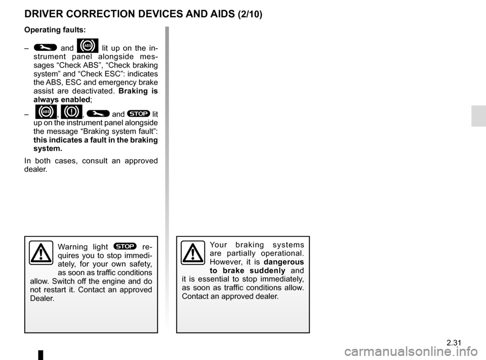
Operating faults:
–
© and x lit up on the in-
strument panel alongside mes-
sages “Check ABS”, “Check braking
system” and “Check ESC”: indicates
the ABS, ESC and emergency brake
assist are deactivated. Braking is
always enabled;
–
x, D, © and ® lit
up on the instrument panel alongside
the message “Braking system fault”:
this indicates a fault in the braking
system.
In both cases, consult an approved
dealer.
Your braking systems
are partially operational.
However, it is dangerous
to brake suddenly and
it is essential to stop immediately,
as soon as traffic conditions allow.
Contact an approved dealer.Warning light ® re-
quires you to stop immedi-
ately, for your own safety,
as soon as traffic conditions
allow. Switch off the engine and do
not restart it. Contact an approved
Dealer.
Page 144 of 346
2.32
Electronic stability control
ESC with understeer control
and traction control
Electronic stability control ESC
This system helps you to keep control
of the vehicle in critical driving condi-
tions (avoiding an obstacle, loss of grip
on a bend, etc.).
Operating principle
A sensor in the steering wheel detects
the direction selected by the driver.
Other sensors throughout the vehicle
measure the actual direction.
The system compares driver input to
the actual trajectory of the vehicle and
corrects the trajectory if necessary by
controlling the braking of certain wheels
and/or engine power. In the event that
the system is engaged, indicator light
flashes on the instrument panel.Understeer control
This system optimises the action of the
ESC in the case of pronounced under-
steer (loss of front axle road holding).
Traction control
This system helps to limit wheelspin of
the drive wheels and to control the ve-
hicle when pulling away accelerating or
decelerating.
Operating principle
Using the wheel sensors, the system
measures and compares the speed of
the drive wheels at all times and slows
down their over-rotation. If a wheel is
starting to slip, the system brakes au-
tomatically until the drive supplied be-
comes compatible with the level of grip
under the wheel again.
The system also adjusts the engine
speed to the grip available under the
wheels, independently of the pressure
exerted on the accelerator pedal.
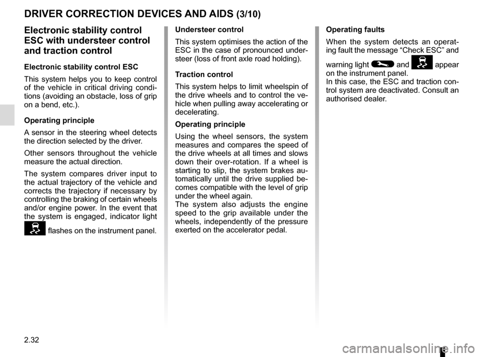
Operating faults
When the system detects an operat-
ing fault the message “Check ESC” and
warning light
© and appear
on the instrument panel.
In this case, the ESC and traction con-
trol system are deactivated. Consult an
authorised dealer.
DRIVER CORRECTION DEVICES AND AIDS (3/10)
Page 158 of 346
2.46
Operating faults
If the system detects a fault, the mes-
sage “Check blind spot alert” is dis-
played on the instrument panel. Consult
an authorised dealer.
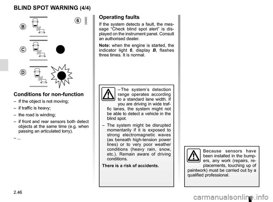
Note: when the engine is started, the
indicator light 6, display B , flashes
three times. It is normal.
– The system’s detection
range operates according
to a standard lane width. If
you are driving in wide traf-
fic lanes, the system might not
be able to detect a vehicle in the
blind spot.
– The system might be disrupted momentarily if it is exposed to
strong electromagnetic waves
(as beneath high-tension power
lines) or to very poor weather
conditions (heavy rain, snow,
etc.). Remain aware of driving
conditions.
There is a risk of accidents.
BLIND SPOT WARNING (4/4)
Because sensors have
been installed in the bump-
ers, any work (repairs, re-
placements, touching up of
paintwork) must be carried out by a
qualified professional.
6
B
C
D
Conditions for non-function
– If the object is not moving;
– if traffic is heavy;
– the road is winding;
– if front and rear sensors both detect objects at the same time (e.g. when
passing an articulated lorry).
– ...
Page 178 of 346
2.66
ADAPTIVE CRUISE CONTROL (6/7)
This function is an additional driving aid. This function is not under any
circumstances intended to replace the due care and attention of the
driver, who should at all times be in control of the vehicle.
The driver should always adapt their speed to the traffic conditions, re-
gardless of the system indications.
The system should under no circumstances be taken to be an obstacle dete\
ctor
or an anti-collision system.
System servicing/repairs
– In the event of an impact, the sensor alignment may become changed, and \
its operation will consequently be affected. Deactivate the function, then consult
an authorised dealer.
– Any work in the area where the radar is located (repairs, replacements,\
touch- ing up of paintwork) must be carried out by a qualified professional.
System disturbance
In a complex environment (metal bridge, etc.), the system may be affected.
Risk of inadvertent braking.
Operating faults
When the system detects an operating
fault, the
warning light lights up
on the instrument panel, with the mes-
sage “Check cruise control”.
There are two possibilities:
– the system is temporarily disrupted (for example: radar obscured by
dirt, mud, snow etc.). In this case,
park the vehicle and switch off the
engine. Clean the detection zone of
the radar. When you next start the
engine, the warning light and the
message go out.
– Otherwise, this may be caused by another fault. Consult an approved
dealer
Page 255 of 346
4.3
BONNET (2/2)
Closing the bonnet
Check that nothing has been left in the
engine compartment.
To close the bonnet again, hold the
bonnet in the middle and guide it down,
allowing a 30 cm gap before it is closed,
then release it. It will latch automatically
under its own weight.
Ensure that the bonnet is
properly locked.
Check that nothing is pre-
venting the catch from lock-
ing (gravel, cloth, etc.).
After carrying out any work
in the engine compart-
ment, check that nothing
has been left behind (cloth,
tools, etc.).
These may damage the engine or
cause a fire.
In the event of even a slight
impact involving the radia-
tor grille or bonnet, have the
bonnet lock checked by an
authorised dealer as soon as pos-
sible.
Page 261 of 346
4.9
LEVELS (2/3)
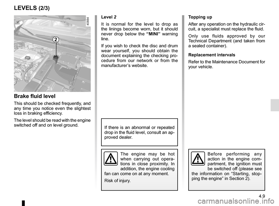
Brake fluid level
This should be checked frequently, and
any time you notice even the slightest
loss in braking efficiency.
The level should be read with the engine
switched off and on level ground.Level 2
It is normal for the level to drop as
the linings become worn, but it should
never drop below the “MINI” warning
line.
If you wish to check the disc and drum
wear yourself, you should obtain the
document explaining the checking pro-
cedure from our network or from the
manufacturer’s website. Topping up
After any operation on the hydraulic cir-
cuit, a specialist must replace the fluid.
Only use fluids approved by our
Technical Department (and taken from
a sealed container).
Replacement intervals
Refer to the Maintenance Document for
your vehicle.
The engine may be hot
when carrying out opera-
tions in close proximity. In
addition, the engine cooling
fan can come on at any moment.
Risk of injury.
2
Before performing any
action in the engine com-
partment, the ignition must
be switched off (please see
the information on “Starting, stop-
ping the engine” in Section 2).
If there is an abnormal or repeated
drop in the fluid level, consult an ap-
proved dealer.
Page 284 of 346
5.14
FRONT HEADLIGHTS: replacing the bulbs (1/2)
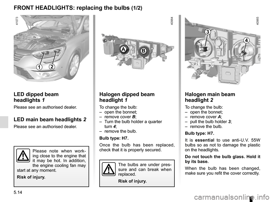
3
4
Halogen dipped beam
headlight 1
To change the bulb:
– open the bonnet;
– remove cover B;
– Turn the bulb holder a quarter turn 4;
– remove the bulb.
Bulb type: H7.
Once the bulb has been replaced,
check that it is properly secured.
BA
Halogen main beam
headlight 2
To change the bulb:
– open the bonnet;
– remove cover A;
– pull the bulb holder 3;
– remove the bulb.
Bulb type: H7.
It is essential to use anti-U.V. 55W
bulbs so as not to damage the plastic
on the headlights.
Do not touch the bulb glass. Hold it
by its base.
When the bulb has been changed,
make sure you refit the cover correctly.
The bulbs are under pres-
sure and can break when
replaced.
Risk of injury.
12
Please note when work-
ing close to the engine that
it may be hot. In addition,
the engine cooling fan may
start at any moment.
Risk of injury.
LED dipped beam
headlights 1
Please see an authorised dealer.
LED main beam headlights 2
Please see an authorised dealer.
Page 305 of 346
5.35
WIPER BLADES: REPLACEMENT (1/2)
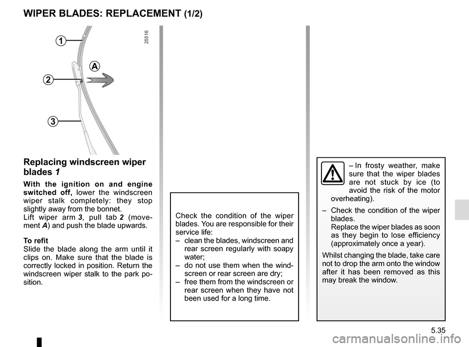
Replacing windscreen wiper
blades 1
With the ignition on and engine
switched off, lower the windscreen
wiper stalk completely: they stop
slightly away from the bonnet.
Lift wiper arm 3, pull tab 2 (move-
ment A) and push the blade upwards.
To refit
Slide the blade along the arm until it
clips on. Make sure that the blade is
correctly locked in position. Return the
windscreen wiper stalk to the park po-
sition.
1
2
3
Check the condition of the wiper
blades. You are responsible for their
service life:
– clean the blades, windscreen and rear screen regularly with soapy
water;
– do not use them when the wind- screen or rear screen are dry;
– free them from the windscreen or rear screen when they have not
been used for a long time.
A
– In frosty weather, make
sure that the wiper blades
are not stuck by ice (to
avoid the risk of the motor
overheating).
– Check the condition of the wiper
blades.
Replace the wiper blades as soon
as they begin to lose efficiency
(approximately once a year).
Whilst changing the blade, take care
not to drop the arm onto the window
after it has been removed as this
may break the window.