Emergency start RENAULT MEGANE 2017 4.G Owners Manual
[x] Cancel search | Manufacturer: RENAULT, Model Year: 2017, Model line: MEGANE, Model: RENAULT MEGANE 2017 4.GPages: 346, PDF Size: 7.04 MB
Page 25 of 346
1.19
AUTOMATIC LOCKING WHEN DRIVING
Operating principleAfter the vehicle is started, the system
automatically locks the doors when you
are driving at approximately 6 mph
(10 km/h) and over.
The door can be unlocked:
– by pressing central door unlocking
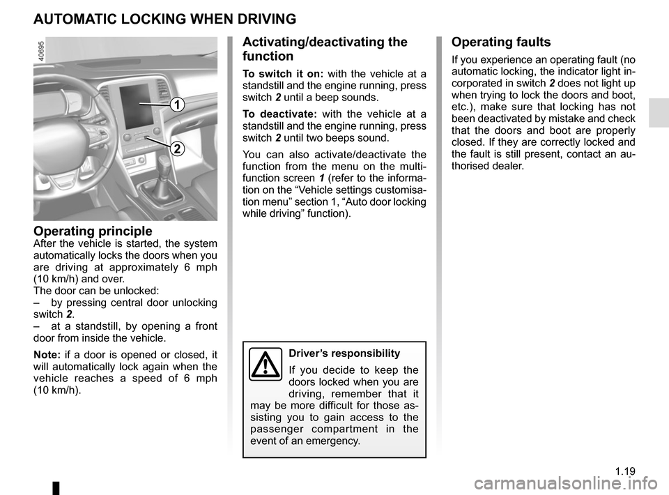
switch 2.
– at a standstill, by opening a front
door from inside the vehicle.
Note: if a door is opened or closed, it
will automatically lock again when the
vehicle reaches a speed of 6 mph
(10 km/h).
Activating/deactivating the
function
To switch it on: with the vehicle at a
standstill and the engine running, press
switch 2 until a beep sounds.
To deactivate: with the vehicle at a
standstill and the engine running, press
switch 2 until two beeps sound.
You can also activate/deactivate the
function from the menu on the multi-
function screen 1 (refer to the informa-
tion on the “Vehicle settings customisa-
tion menu” section 1, “Auto door locking
while driving” function).
Operating faults
If you experience an operating fault (no
automatic locking, the indicator light in-
corporated in switch 2 does not light up
when trying to lock the doors and boot,
etc.), make sure that locking has not
been deactivated by mistake and check
that the doors and boot are properly
closed. If they are correctly locked and
the fault is still present, contact an au-
thorised dealer.
2
Driver’s responsibility
If you decide to keep the
doors locked when you are
driving, remember that it
may be more difficult for those as-
sisting you to gain access to the
passenger compartment in the
event of an emergency.
1
Page 59 of 346
1.53
AUDIBLE AND VISUAL SIGNALS
Horn
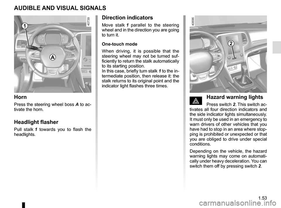
Press the steering wheel boss A to ac-
tivate the horn.
Headlight flasher
Pull stalk 1 towards you to flash the
headlights.
éHazard warning lights
Press switch 2. This switch ac-
tivates all four direction indicators and
the side indicator lights simultaneously.
It must only be used in an emergency to
warn drivers of other vehicles that you
have had to stop in an area where stop-
ping is prohibited or unexpected or that
you are obliged to drive under special
conditions.
Depending on the vehicle, the hazard
warning lights may come on automati-
cally under heavy deceleration. You can
switch them off by pressing switch 2.
Direction indicators
Move stalk 1 parallel to the steering
wheel and in the direction you are going
to turn it.
One-touch mode
When driving, it is possible that the
steering wheel may not be turned suf-
ficiently to return the stalk automatically
to its starting position.
In this case, briefly turn stalk 1 to the in-
termediate position, then release it: the
stalk returns to its original point and the
indicator light flashes three times.
2
A
1
Page 68 of 346

The display of information shown below DEPENDS ON THE VEHICLE EQUIPMENT \
AND COUNTRY.
Assisted parking brake fault
light
Please refer to the information on the
“Assis")
1.62
WARNING LIGHTS (5/6)
The display of information shown below DEPENDS ON THE VEHICLE EQUIPMENT \
AND COUNTRY.
Assisted parking brake fault
light
Please refer to the information on the
“Assisted parking brake” in Section 2.
Emergency active brake
assist
Refer to the information on “Driving cor-
rection devices and aids” in Section 2.
\bECO mode warning light
This comes on when ECO
mode is activated.
Please refer to the information on “Eco-
driving” in Section 2.
Tyre pressure monitoring
system
Refer to the information on the “Tyre
pressure monitoring system” in
Section 2.
Rear seat belt reminder (depending
on vehicle)
Warning light
ß comes on, accom-
panied (depending on the vehicle) by
a message indicating the number of
fastened seat belts on the instrument
panel for approximately 30 seconds,
each time the vehicle is started, a door
is opened or a rear seat belt is fas-
tened/unfastened. Check that the rear
passengers are wearing seat belts and
that the number of seat belts shown as
fastened corresponds to the number of
rear seat places occupied.
Engine standby warning
light
Please see information in the para-
graph on “Stop and Start Function” in
Section 2.
Unavailability of engine
standby warning light
Please see information in the para-
graph on “Stop and Start Function” in
Section 2.
ÐÎSpeed limiter warning
lights
Refer to the information on the “Speed
limiter” in Section 2.
ÏΦ Cruise control
warning lights
Refer to the information on “Cruise con-
trol” in Section 2.
\fAdaptive cruise control
warning light
Refer to the information on “Cruise con-
trol” in Section 2.
Page 139 of 346
2.27
TYRE PRESSURE MONITORING SYSTEM (1/3)
If the vehicle is equipped with the func-
tion, this system monitors the tyre pres-
sure.
Operating principle
Each wheel (except for the emergency
spare wheel) has a sensor in the infla-
tion valve which periodically measures
the tyre pressure.
The system displays the current pres-
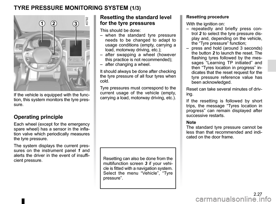
sures on the instrument panel 1 and
alerts the driver in the event of insuffi-
cient pressure.
Resetting the standard level
for the tyre pressures
This should be done:
– when the standard tyre pressure needs to be changed to adapt to
usage conditions (empty, carrying a
load, motorway driving, etc.);
– after swapping a wheel (however this practice is not recommended);
– after changing a wheel.
It should always be done after checking
the tyre pressure of all four tyres when
cold.
Tyre pressures must correspond to the
current usage of the vehicle (empty,
carrying a load, motorway driving, etc.).
21
Resetting procedure
With the ignition on:
– repeatedly and briefly press con- trol 2 to select the tyre pressure dis-
play and, depending on the vehicle,
the “Tyre pressure” function;
– press and hold (around 3 seconds) the button 2 to launch the reset. The
flashing tyres followed by the mes-
sages “Learning TP initiated” and
then “Tyres location in progress” in-
dicates that the reset request for the
tyre pressure reference value has
been acknowledged.
Reset can take several minutes of driv-
ing.
If the resetting is followed by short
trips, the message “Tyres location in
progress” can remain displayed after
successive restarts.
Note
The standard tyre pressure cannot be
less than that recommended and indi-
cated on the door frame.
3
Resetting can also be done from the
multifunction screen 3 if your vehi-
cle is fitted with a navigation system.
Select the menu “Vehicle”, “Tyre
pressure”.
Page 142 of 346
2.30
DRIVER CORRECTION DEVICES AND AIDS (1/10)ABS (anti-lock braking
system)
Under heavy braking, the ABS prevents
the wheels from locking, allowing the
stopping distance to be managed and
keeping control of the vehicle.
Under these circumstances, the vehi-
cle can be steered to avoid an obstacle
whilst braking. In addition, this system
can increase stopping distances, par-
ticularly on roads with low surface grip
(wet ground etc.).
You will feel a pulsation through the
brake pedal each time the system is
activated. The ABS does not in any way
improve the vehicle's physical perform-
ance relating to the road surface and
roadholding. It is still essential to follow
the rules of good driving practice (such
as driving at a safe distance from the
vehicle in front etc.).
– ABS (anti-lock braking system);
– ESC
(electronic stability control)
with understeer control and trac-
tion control;
– emergency brake assist;
– active emergency braking;
– hill start assistance;
– rear wheel steering.
Other driving assistance systems are
detailed on the following pages.
In an emergency, apply firm and
continuous pressure to the brake
pedal. There is no need to pump
it repeatedly. The ABS will modu-
late the force applied in the braking
system.
These functions are an ad-
ditional aid in the event of
critical driving conditions,
enabling the vehicle behav-
iour to be adapted to suit the driving
conditions.
However, the functions do not take
the place of the driver. They do
not increase the vehicle’s limits
and should not encourage you
to drive more quickly. Therefore,
they can under no circumstances
replace the vigilance or responsibil-
ity of the driver when manoeuvring
the vehicle (the driver must always
be ready for sudden incidents which
may occur when driving).
Page 143 of 346
2.31
DRIVER CORRECTION DEVICES AND AIDS (2/10)
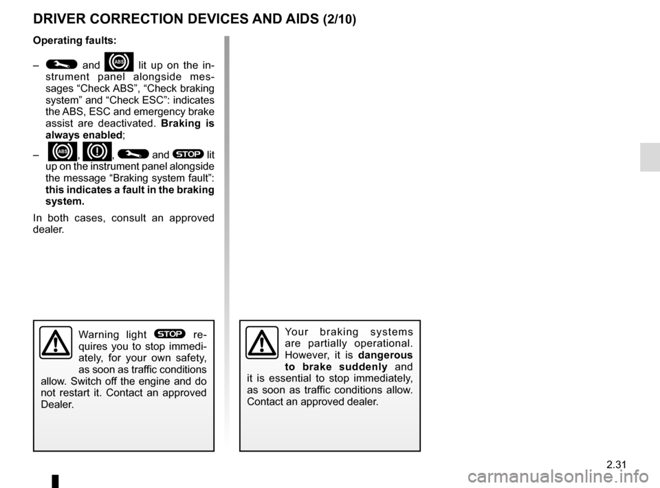
Operating faults:
–
© and x lit up on the in-
strument panel alongside mes-
sages “Check ABS”, “Check braking
system” and “Check ESC”: indicates
the ABS, ESC and emergency brake
assist are deactivated. Braking is
always enabled;
–
x, D, © and ® lit
up on the instrument panel alongside
the message “Braking system fault”:
this indicates a fault in the braking
system.
In both cases, consult an approved
dealer.
Your braking systems
are partially operational.
However, it is dangerous
to brake suddenly and
it is essential to stop immediately,
as soon as traffic conditions allow.
Contact an approved dealer.Warning light ® re-
quires you to stop immedi-
ately, for your own safety,
as soon as traffic conditions
allow. Switch off the engine and do
not restart it. Contact an approved
Dealer.
Page 148 of 346
2.36
DRIVER CORRECTION DEVICES AND AIDS (7/10)
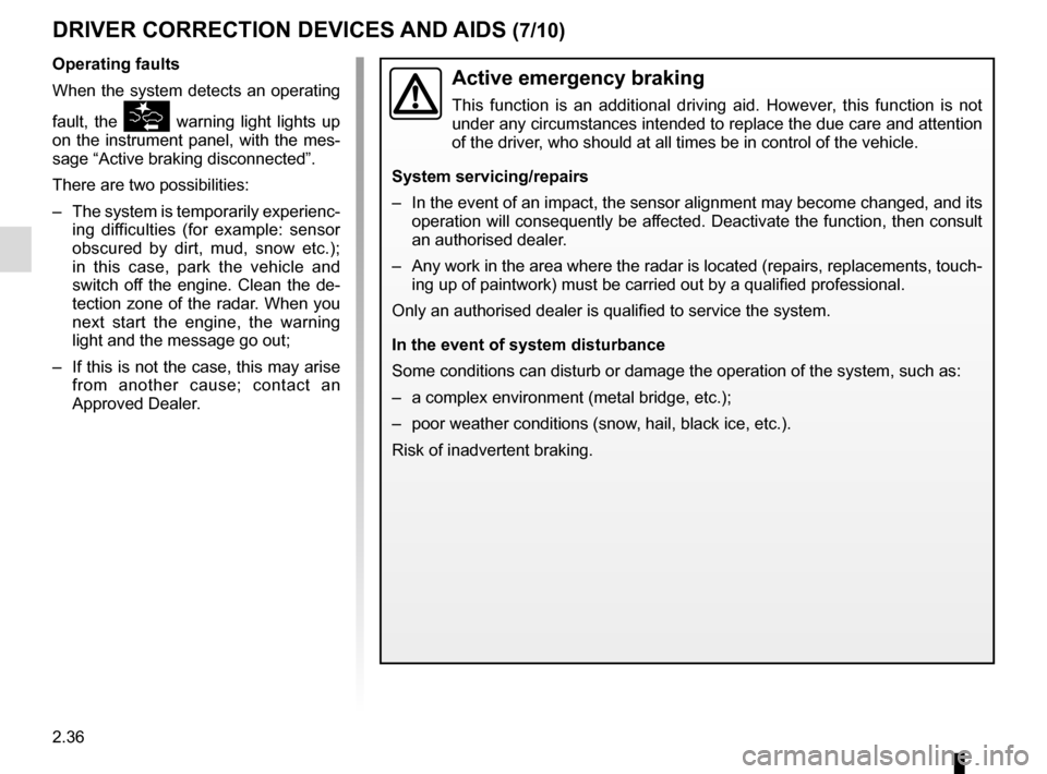
Active emergency braking
This function is an additional driving aid. However, this function is not
under any circumstances intended to replace the due care and attention
of the driver, who should at all times be in control of the vehicle.
System servicing/repairs
– In the event of an impact, the sensor alignment may become changed, and \
its operation will consequently be affected. Deactivate the function, then consult
an authorised dealer.
– Any work in the area where the radar is located (repairs, replacements,\
touch- ing up of paintwork) must be carried out by a qualified professional.
Only an authorised dealer is qualified to service the system.
In the event of system disturbance
Some conditions can disturb or damage the operation of the system, such \
as:
– a complex environment (metal bridge, etc.);
– poor weather conditions (snow, hail, black ice, etc.).
Risk of inadvertent braking.
Operating faults
When the system detects an operating
fault, the
warning light lights up
on the instrument panel, with the mes-
sage “Active braking disconnected”.
There are two possibilities:
– The system is temporarily experienc- ing difficulties (for example: sensor
obscured by dirt, mud, snow etc.);
in this case, park the vehicle and
switch off the engine. Clean the de-
tection zone of the radar. When you
next start the engine, the warning
light and the message go out;
– If this is not the case, this may arise from another cause; contact an
Approved Dealer.
Page 310 of 346

5.40
The following advice will enable you to carry out quick, temporary repai\
rs. For safety reasons you should always contact
an approved dealer as soon as possible.
Using the remote controlPOSSIBLE CAUSES ACTION REQUIRED
The remote control does not lock or
unlock the doors. The remote control battery is flat.
Use the emergency key.
Use of appliances operating on the same
frequency as the remote control (mobile
phone, etc.). Stop using the devices or use the key.
Vehicle located in a high electromagnetic
radiation zone.
Discharged battery. Replace the battery. You can still lock/
unlock and start your vehicle (refer to the
information on “Locking/unlocking the
doors” in Section 1 and “Starting/Stopping
the engine” in Section 2).
The vehicle is started. With the engine running, the key’s locking/
unlocking device is blocked. Turn off the
ignition.
OPERATING FAULTS (2/7)
Page 340 of 346
7.2
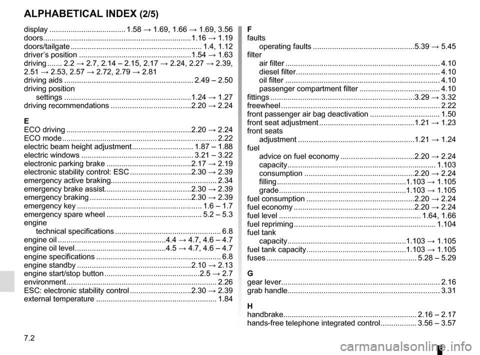
ALPHABETICAL INDEX (2/5)
display .................................... 1.58 → 1.69, 1.66 → 1.69, 3.56
doors......................................................................1.16 → 1.19
doors/tailgate .........................................................\
..... 1.4, 1.12
driver’s position .....................................................1.54 → 1.63
driving ....... 2.2 → 2.7, 2.14 – 2.15, 2.17 → 2.24, 2.27 → 2.39,
2.51 → 2.53, 2.57 → 2.72, 2.79 → 2.81
driving aids ............................................................. 2.49 – 2.50
driving position settings ............................................................1.24 → 1.27
driving recommendations ......................................2.20 → 2.24
E
ECO driving ...........................................................2.20 → 2.24
ECO mode ........................................................................\
. 2.22
electric beam height adjustment ............................. 1.87 – 1.88
electric windows ..................................................... 3.21 – 3.22
electronic parking brake ........................................2.17 → 2.19
electronic stability control: ESC .............................2.30 → 2.39
emergency active braking.................................................. 2.34
emergency brake assist.........................................2.30 → 2.39
emergency braking ................................................2.30 → 2.39
emergency key ........................................................... 1.6 – 1.7
emergency spare wheel ............................................. 5.2 – 5.3
engine technical specifications .................................................. 6.8
engine oil ...................................................4.4 → 4.7, 4.6 – 4.7
engine oil level ...........................................4.5 → 4.7, 4.6 – 4.7
engine specifications ........................................................... 6.8
engine standby ......................................................2.10 → 2.13
engine start/stop button .............................................2.5 → 2.7
environment ............................................................\
........... 2.26
ESC: electronic stability control .............................2.30 → 2.39
external temperature ......................................................... 1.84 F
faults
operating faults ................................................5.39 → 5.45
filter air filter ........................................................................\
. 4.10
diesel filter .................................................................... 4.10
oil filter ........................................................................\
. 4.10
passenger compartment filter ...................................... 4.10
fittings ...............................................................\
.....3.29 → 3.32
freewheel ..............................................................\
............. 2.22
front passenger air bag deactivation ................................. 1.50
front seat adjustment .............................................1.21 → 1.23
front seats adjustment .......................................................1.21 → 1.24
fuel advice on fuel economy ...................................2.20 → 2.24
capacity ...............................................................\
....... 1.103
consumption ....................................................2.20 → 2.24
filling .............................................................1.103 → 1.105
grade ............................................................1.103 → 1.105
fuel consumption ...................................................2.20 → 2.24
fuel economy .........................................................2.20 → 2.24
fuel level ................................................................... 1.64, 1.66
fuel repriming
................................................................... 1.104
fuel tank capacity ........................................................1.103 → 1.105
fuel tank capacity ...............................................1.103 → 1.105
fuses ....................................................................... 5.28 – 5.29
G
gear lever........................................................................\
... 2.16
grab handle........................................................................\
3.31
H
handbrake............................................................... 2.16 – 2.17
hands-free telephone integrated control ................. 3.56 – 3.57