stop start RENAULT MEGANE COUPE CABRIOLET 2016 X95 / 3.G Owner's Manual
[x] Cancel search | Manufacturer: RENAULT, Model Year: 2016, Model line: MEGANE COUPE CABRIOLET, Model: RENAULT MEGANE COUPE CABRIOLET 2016 X95 / 3.GPages: 242, PDF Size: 5.06 MB
Page 93 of 242
2.7
STOP AND START function (2/3)
Conditions preventing the
standby of the engine
Certain conditions prevent the system
from using the engine standby function,
including when:
– reverse gear is engaged;
– the bonnet is not locked;
– the driver’s door is not closed;
– the driver’s seatbelt is not fastened;
– the outdoor temperature is too low or too high (less than around 0 °C or
higher than around 30 °C);
– the battery is not sufficiently char- ged;
– the difference between the vehicle interior temperature and the automa-
tic climate control instruction is too
high; – the “Clear View” function is activa-
ted (please see “Automatic Climate
Control” in Section 3);
– the engine coolant temperature is too low;
– automatic particle filter cleaning is underway;
or
– ...
The message “Auto Stop Unavailable”
on the instrument panel indicates that
the engine is on standby.
To fill up with fuel, the engine must
be stopped (and not on standby):
always stop the engine by pressing
the engine stop button (please see
“Starting, stopping the engine)”.
Special cases
– While the system is operating, and the engine is stopped (traffic jam,
traffic lights, etc.), if the driver gets
out of their seat or unfastens their
seatbelt and opens the driver’s door,
the ignition will be switched off and,
depending on the vehicle, the elec-
tronic parking brake will be automa-
tically deployed. To restart and reac-
tivate the Stop and Start system,
press the start button (please see
“Starting, stopping the engine”).
– In the event of the engine stalling, if the system is operational, press
down the clutch pedal as far as it will
go to restart.
Page 94 of 242
2.8
Operating faults
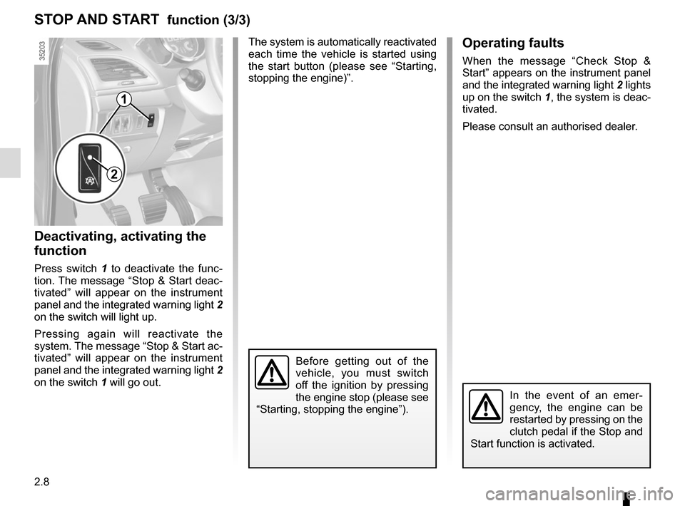
When the message “Check Stop &
Start” appears on the instrument panel
and the integrated warning light 2 lights
up on the switch 1, the system is deac-
tivated.
Please consult an authorised dealer.
Deactivating, activating the
function
Press switch 1 to deactivate the func-
tion. The message “Stop & Start deac-
tivated” will appear on the instrument
panel and the integrated warning light 2
on the switch will light up.
Pressing again will reactivate the
system. The message “Stop & Start ac-
tivated” will appear on the instrument
panel and the integrated warning light 2
on the switch 1 will go out.
STOP AND START function (3/3)
The system is automatically reactivated
each time the vehicle is started using
the start button (please see “Starting,
stopping the engine)”.
Before getting out of the
vehicle, you must switch
off the ignition by pressing
the engine stop (please see
“Starting, stopping the engine”).
1
2
In the event of an emer-
gency, the engine can be
restarted by pressing on the
clutch pedal if the Stop and
Start function is activated.
Page 98 of 242
2.12
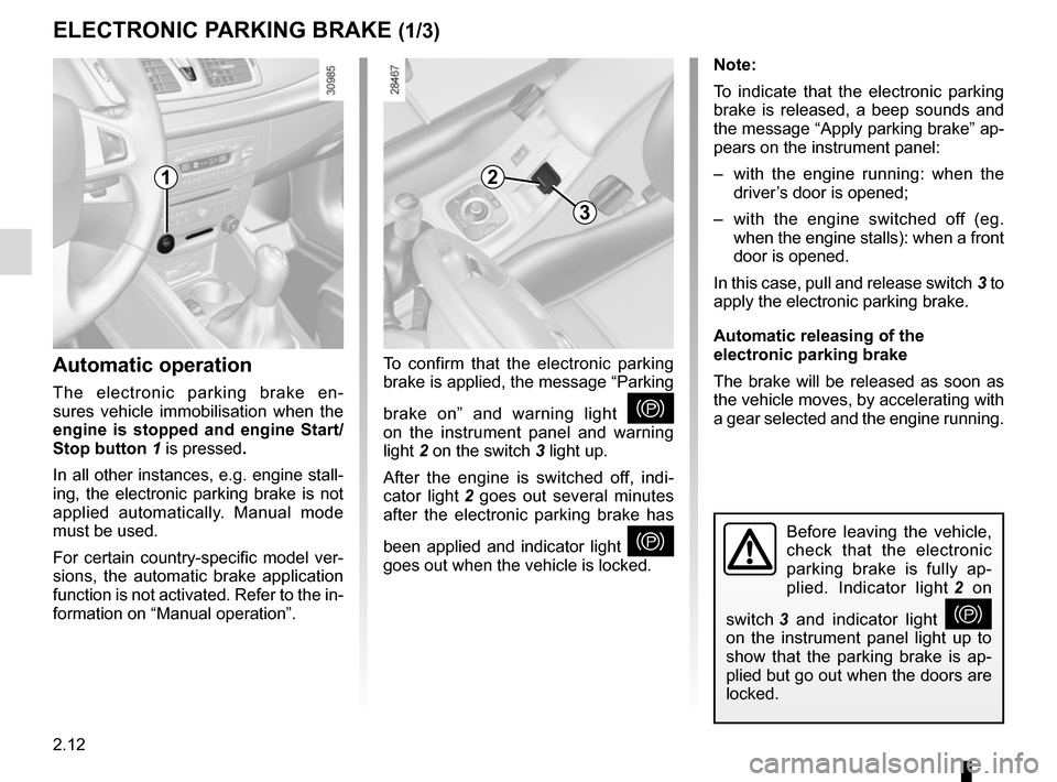
Before leaving the vehicle,
check that the electronic
parking brake is fully ap-
plied. Indicator light 2 on
switch 3 and indicator light
}
on the instrument panel light up to
show that the parking brake is ap-
plied but go out when the doors are
locked.
Note:
To indicate that the electronic parking
brake is released, a beep sounds and
the message “Apply parking brake” ap-
pears on the instrument panel:
– with the engine running: when the driver’s door is opened;
– with the engine switched off (eg. when the engine stalls): when a front
door is opened.
In this case, pull and release switch 3 to
apply the electronic parking brake.
Automatic releasing of the
electronic parking brake
The brake will be released as soon as
the vehicle moves, by accelerating with
a gear selected and the engine running.
Automatic operation
The electronic parking brake en-
sures vehicle immobilisation when the
engine is stopped and engine Start/
Stop button 1 is pressed.
In all other instances, e.g. engine stall-
ing, the electronic parking brake is not
applied automatically. Manual mode
must be used.
For certain country-specific model ver-
sions, the automatic brake application
function is not activated. Refer to the in-
formation on “Manual operation”.
ELECTRONIC PARKING BRAKE (1/3)
To confirm that the electronic parking
brake is applied, the message “Parking
brake on” and warning light
}
on the instrument panel and warning
light 2 on the switch 3 light up.
After the engine is switched off, indi-
cator light 2 goes out several minutes
after the electronic parking brake has
been applied and indicator light
}
goes out when the vehicle is locked.
12
3
Page 99 of 242
2.13
Special cases
When parking on a slope or towing a
trailer, pull switch 3 for a few seconds
to obtain the maximum braking effect.
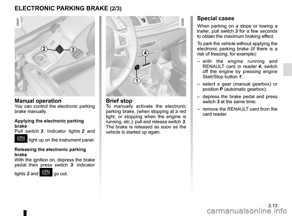
To park the vehicle without applying the
electronic parking brake (if there is a
risk of freezing, for example):
– with the engine running and RENAULT card in reader 4, switch
off the engine by pressing engine
Start/Stop button 1;
– select a gear (manual gearbox) or position P (automatic gearbox);
– depress the brake pedal and press switch 3 at the same time;
– remove the RENAULT card from the card reader.
Brief stopTo manually activate the electronic
parking brake, (when stopping at a red
light, or stopping when the engine is
running, etc.): pull and release switch 3.
The brake is released as soon as the
vehicle is started up again.
ELECTRONIC PARKING BRAKE (2/3)
4
1
3
Manual operationYou can control the electronic parking
brake manually.
Applying the electronic parking
brake
Pull switch 3. Indicator lights 2 and
} light up on the instrument panel.
Releasing the electronic parking
brake
With the ignition on, depress the brake
pedal then press switch 3: indicator
lights 2 and
} go out.
2
Page 104 of 242
2.18
MAINTENANCE AND ANTIPOLLUTION ADVICE
Your vehicle complies with criteria for
recycling and recovering vehicles at the
end of their service life, which will come
into force in 2015.
Some of the parts on your vehicle have
been designed to be recycled later.
These parts are easily removable in
order to be collected and reprocessed
in recycling networks.
Furthermore, by virtue of its design,
moderate fuel consumption and initial
settings, your vehicle also conforms
to current anti-pollution regulations.
The manufacturer is actively striving
to reduce pollutant exhaust gas emis-
sions and to save energy. However,
the fuel consumption of your vehicle
and the level of pollutant exhaust gas
emissions are also your responsibility.
Ensure that it is maintained and used
correctly.Maintenance
It is important to remember that fail-
ure to respect anti-pollution regulations
could lead to legal action being taken
against the vehicle owner.
In addition, replacing engine, fuel
supply system and exhaust compo-
nents with parts other than those origi-
nally recommended by the manufac-
turer may alter your vehicle so that it
no longer complies with anti-pollution
regulations.
Have your vehicle adjusted and
checked by an authorised dealer, in ac-
cordance with the instructions given in
your maintenance schedule: they will
have all the equipment necessary for
ensuring that your vehicle is maintained
to its original standard.
Engine adjustments
– Air filter, fuel filter: a choked ele-
ment will reduce efficiency. It must
be replaced.
– Idle speed: no adjustment is needed.
Exhaust gas monitoring
system
The exhaust gas monitoring system will
detect any operating faults in the vehi-
cle’s antipollution system.
If this system malfunctions, toxic sub-
stances may be released into the at-
mosphere or damage may occur.
ÄThis warning light on the in-
strument panel will indicate if
there are any faults in the system:
This lights up when the ignition is
switched on and goes out when the
engine is started.
– If it lights up continuously, consult an approved Dealer as soon as possi-
ble;
– if it flashes, reduce the engine speed until the light stops flashing. Contact
an authorised dealer as soon as pos-
sible.
Page 110 of 242
2.24
DRIVER CORRECTION DEVICES AND AIDS (1/4)
Depending on the vehicle, this is com-
posed of:
– the ABS (anti-lock braking
system);
– electronic stability control ESC
with understeer control and trac-
tion control;
– emergency brake assist with, de- pending on the vehicle, braking
anticipation;
– hill start assistance.
In an emergency, apply firm and
continuous pressure to the brake
pedal. There is no need to pump
it repeatedly. The ABS will modu-
late the force applied in the braking
system.
These functions are an ad-
ditional aid in the event of
critical driving conditions,
enabling the vehicle behav-
iour to be adapted to suit the driving
conditions.
However, the functions do not take
the place of the driver. They do
not increase the vehicle’s limits
and should not encourage you
to drive more quickly. Therefore,
they can under no circumstances
replace the vigilance or responsibil-
ity of the driver when manoeuvring
the vehicle (the driver must always
be ready for sudden incidents which
may occur when driving).
Your braking systems
are partially operational.
However, it is dangerous
to brake suddenly and
it is essential to stop immediately,
as soon as traffic conditions allow.
Contact an approved dealer.
Operating faults:
–
© and x lit on the instru-
ment panel with the messages
“Check ABS”, “Check braking
system” and “Check ESC”: ABS,
ESC and the emergency brake
assist are deactivated. Braking is
always enabled;
–
x, D, © and ® lit
up on the instrument panel alongside
the message “Braking system fault”:
this indicates a fault in the braking
system.
In both cases, consult an approved
Dealer.
ABS (anti-lock braking
system)
Under heavy braking, the ABS prevents
the wheels from locking, allowing the
stopping distance to be managed and
keeping control of the vehicle.
Under these circumstances, the vehi-
cle can be steered to avoid an obstacle
whilst braking. In addition, this system
can increase stopping distances, par-
ticularly on roads with low surface grip
(wet ground etc.).
You will feel a pulsation through the
brake pedal each time the system is
activated. The ABS does not in any
way improve the vehicle’s physical per-
formance relating to the road surface
and road-holding. It is still essential to
follow the rules of good driving practice
(such as driving at a safe distance from
the vehicle in front, etc.).
Page 113 of 242
2.27
DRIVER CORRECTION DEVICES AND AIDS (4/4)
Hill start assistance
This device assists the driver when
starting on hills (ascending or descend-
ing). It prevents the vehicle from rolling
forwards or backwards by automatically
applying the brakes when the driver lifts
their foot off the brake pedal to depress
the accelerator pedal.
System operation
It only operates when the gear lever is
in a position other than neutral (other
than N or P for automatic transmis-
sions) and the vehicle is completely
stationary (brake pedal depressed).
The system holds the vehicle for ap-
proximately 2 seconds. The brakes are
then gradually released (the vehicle will
move according to the slope).The hill start assistance
system cannot completely
prevent the vehicle from
rolling backwards in all sit-
uations (extremely steep gradients,
etc.).
In all cases, the driver may depress
the brake pedal to prevent the ve-
hicle from rolling forwards or back-
wards.
The hill start assistance function
should not be used for prolonged
stops: use the brake pedal.
This function is not designed to im-
mobilise the vehicle permanently.
If necessary, use the brake pedal to
stop the vehicle.
The driver must remain particularly
vigilant when driving on slippery or
low-grip surfaces and/or on hills.
Risk of serious injury.
Page 132 of 242
3.4
RETRACTABLE GLASS ROOF: opening
Before opening the roof
– Perform the procedure with the engine running (risk of battery dis-
charging) and the vehicle stationary.
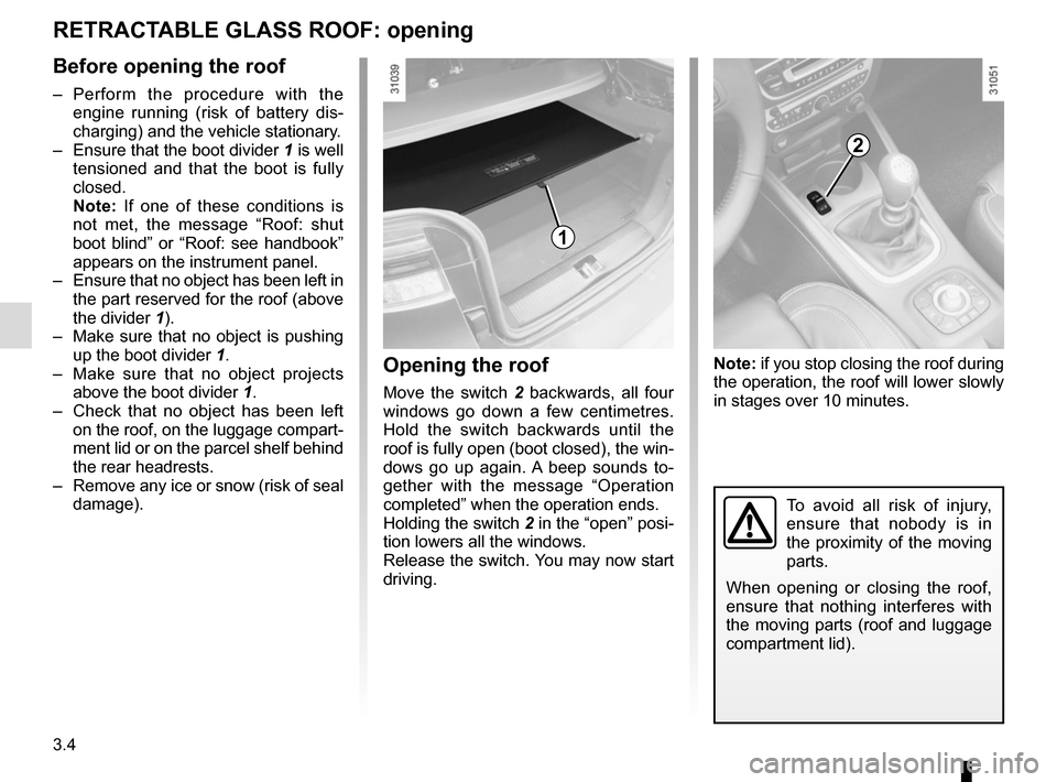
– Ensure that the boot divider 1 is well
tensioned and that the boot is fully
closed.
Note: If one of these conditions is
not met, the message “Roof: shut
boot blind” or “Roof: see handbook”
appears on the instrument panel.
– Ensure that no object has been left in the part reserved for the roof (above
the divider 1).
– Make sure that no object is pushing up the boot divider 1.
– Make sure that no object projects above the boot divider 1.
– Check that no object has been left on the roof, on the luggage compart-
ment lid or on the parcel shelf behind
the rear headrests.
– Remove any ice or snow (risk of seal damage).
To avoid all risk of injury,
ensure that nobody is in
the proximity of the moving
parts.
When opening or closing the roof,
ensure that nothing interferes with
the moving parts (roof and luggage
compartment lid).
1
2
Opening the roof
Move the switch 2 backwards, all four
windows go down a few centimetres.
Hold the switch backwards until the
roof is fully open (boot closed), the win-
dows go up again. A beep sounds to-
gether with the message “Operation
completed” when the operation ends.
Holding the switch 2 in the “open” posi-
tion lowers all the windows.
Release the switch. You may now start
driving. Note: if you stop closing the roof during
the operation, the roof will lower slowly
in stages over 10 minutes.
Page 134 of 242
3.6
RETRACTABLE GLASS ROOF: operating fault (1/2)
In the event of a fault before
or while opening or closing
the roof
There is a beep and the message
“Check roof See handbook”, accom-
panied by the warning light
© ap-
pears on the instrument panel.
Stop pressing the switch 1.
The roof lowers back slowly in stages.
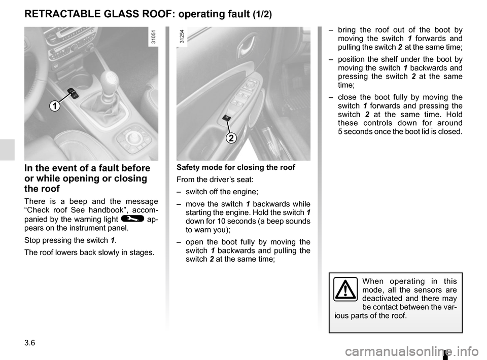
Safety mode for closing the roof
From the driver’s seat:
– switch off the engine;
– move the switch 1 backwards while
starting the engine. Hold the switch 1
down for 10 seconds (a beep sounds
to warn you);
– open the boot fully by moving the switch 1 backwards and pulling the
switch 2 at the same time;
1
– bring the roof out of the boot by moving the switch 1 forwards and
pulling the switch 2 at the same time;
– position the shelf under the boot by moving the switch 1 backwards and
pressing the switch 2 at the same
time;
– close the boot fully by moving the switch 1 forwards and pressing the
switch 2 at the same time. Hold
these controls down for around
5 seconds once the boot lid is closed.
2
When operating in this
mode, all the sensors are
deactivated and there may
be contact between the var-
ious parts of the roof.
Page 140 of 242
3.12
AUTOMATIC CLIMATE CONTROL (1/5)Automatic mode
The automatic climate control system
guarantees comfort in the passen-
ger compartment and good visibility
(except in the event of extreme condi-
tions), whilst optimising consumption.
The system controls the ventilation
speed, air distribution, air recircula-
tion, and starting and stopping the air
conditioning and air temperature. This
mode consists of a choice of three pro-
grammes:
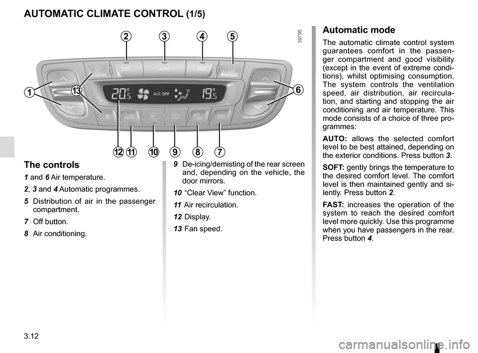
AUTO: allows the selected comfort
level to be best attained, depending on
the exterior conditions. Press button 3.
SOFT: gently brings the temperature to
the desired comfort level. The comfort
level is then maintained gently and si-
lently. Press button 2.
FAST: increases the operation of the
system to reach the desired comfort
level more quickly. Use this programme
when you have passengers in the rear.
Press button 4.
13
4
9 De-icing/demisting of the rear screen
and, depending on the vehicle, the
door mirrors.
10 “Clear View” function.
11 Air recirculation.
12 Display.
13 Fan speed.
6
7891011
32
The controls
1 and 6 Air temperature.
2, 3 and 4 Automatic programmes.
5 Distribution of air in the passenger compartment.
7 Off button.
8 Air conditioning.
12
5
1