clutch RENAULT SCENIC 2010 J95 / 3.G Engine And Pheripherals DCM 1.2 Injection Workshop Manual
[x] Cancel search | Manufacturer: RENAULT, Model Year: 2010, Model line: SCENIC, Model: RENAULT SCENIC 2010 J95 / 3.GPages: 269
Page 8 of 269
13B-8V10 MR-372-J84-13B100$020.mif
13B
DCM 1.2 Injection
Program No.: 4D
Vdiag No.: 48, 4C, 50,
54, 58, 5C
I. HAZARDS ASSOCIATED WITH CONTAMINATION
The high pressure direct injection system is highly sensitive to contamination. The risks associated with
contamination are:
–damage to or destruction of the high pressure injection system,
–components jamming,
–components losing seal integrity.
All After-Sales operations must be performed under very clean conditions. This means that no impurities
(particles a few microns in size) should have entered the system during dismantling.
The cleanliness principle must be applied from the filter to the injectors.
What are the sources of contamination?
–metal or plastic swarf,
–paint,
–fibres: from cardboard,
from brushes,
from paper,
from clothing,
from cloths.
–foreign bodies such as hair,
–ambient air
–etc.
II. ADVICE TO BE FOLLOWED BEFORE ANY OPERATION
Check that you have plugs for the unions to be opened (set of plugs available from the Parts Department). The plugs
are single-use only. After use, they must be discarded (once used they are soiled and cleaning is not sufficient to
make them reusable). Unused plugs must also be discarded.
Check that you have hermetically resealable plastic bags for storing removed parts. Parts stored in this way will be
less susceptible to the risk of contamination. The bags are single-use only. Once used, they must be thrown out.
Use lint-free cleaning cloths (cloth part reference 77 11 211 707). Using normal cloth or paper is prohibited. They are
not lint-free and could contaminate the fuel circuit. Each cloth should only be used once.
Use fresh cleaning agent for each operation (used cleaning agent is contaminated). Pour it into an uncontaminated
container.
For each operation, use a clean brush in good condition (the brush must not shed its bristles).
Use a brush and cleaning agent to clean the unions to be opened.IMPORTANT
Cleaning the engine using a high pressure washer is prohibited because of the risk of damaging connections. In
addition, moisture may collect in the connectors and create electrical connection faults.
IMPORTANT
Before any work is carried out on the high pressure injection system, protect:
–the accessories and timing belts,
–the electrical accessories, (starter, alternator, electric power-assisted steering pump),
–the flywheel surface, to prevent any diesel from running onto the clutch friction plate.
DIESEL INJECTION
Fault finding – Cleanliness guidelines
Page 10 of 269
13B-10V10 MR-372-J84-13B100$030.mif
13B
DCM 1.2 Injection
Program No.: 4D
Vdiag No.: 48, 4C, 50,
54, 58, 5C
High and low pressure pump:
This pump is located upstream of the common rail.
Solenoid injectors:
The injectors are fitted on the cylinder head after the common rail.
Turbocharger:
The turbocharger is located after the exhaust manifold.
Turbocharger control solenoid valve (K9K 724, 766, 802, and 812 only):
This solenoid valve is located close to the turbocharger, is position depends on the vehicle.
Air flowmeter:
The air mass flow meter is located at the air circuit inlet and integrates the air temperature sensor.
EGR valve:
The EGR valve is located between the inlet manifold and the exhaust manifold.
Accelerator pedal potentiometer:
The potentiometer is located on the accelerator pedal.
Clutch pedal switch:
The switch is located on the clutch pedal.
Catalytic converter:
The catalytic converter is located downstream of the turbocharger on the exhaust system.
Cruise control/speed limiter on/off switch:
This switch is located in the passenger compartment to the left of the steering wheel near the lighting dimmer.
Heater plugs:
The heater plugs are located on the cylinder head.
Inlet manifold pressure sensor:
The inlet manifold pressure sensor is located upstream of the turbocharger.
Air temperature sensor:
The air temperature sensor is located at the air circuit inlet, in place of the air flowmeter or integrated into it if
the flowmeter is present, and/or in the inlet manifold.
Water in diesel fuel sensor (New Twingo and Kangoo 2 only):
This sensor is located in the diesel filter.
Fuel temperature sensor:
This sensor is positioned on the injection pump.
Rail pressure sensor:
This sensor is fitted to the common rail.
Atmospheric pressure sensor:
This sensor is incorporated in the computer.
TDC sensor:
This sensor is located on the flywheel.
Camshaft sensor:
This sensor is located at the end of the camshaft.
DIESEL INJECTION
Fault finding – List and location of components
Page 18 of 269
13B-18V10 MR-372-J84-13B100$040.mif
DIESEL INJECTION
Fault finding – Function13B
DCM 1.2 Injection
Program No.: 4D
Vdiag No.: 48, 4C, 50,
54, 58, 5C
Cruise control - speed limiter (CC / SL) management
When activated, the cruise control function maintains the vehicle at a preselected speed, regardless of the
driving conditions encountered. Using the control buttons, the driver can increase or reduce the speed of the vehicle.
The cruise control function can be deactivated either using the control buttons, or by switching off the cruise control
function selector switch or when system events are detected such as the brake or clutch pedal being depressed,
or when system errors are detected such as an inconsistent vehicle speed or excessive vehicle deceleration.
The cruise control function can also be temporarily overridden when the driver wants to resume control of
the vehicle and exceed the selected cruising speed by pressing the accelerator pedal, which causes the controlled
fuel flow to be exceeded. The cruising speed is resumed when the driver releases the accelerator pedal.
It is possible to reactivate cruise control and to return to the last cruising speed after the function has been
deactivated for whatever reason, during the same cycle of use (computer supply voltage not cut off). The vehicle will
then attempt to return to the cruising speed using a controlled vehicle acceleration rate.
When activated (using the selection switch), the vehicle speed limiter function limits the vehicle speed to
a preselected value.
The driver controls the vehicle in the normal way using the accelerator pedal until the limit speed is reached. If an
attempt is made to exceed this speed, the system will ignore the pedal request and will limit the vehicle speed,
provided that the driver continues to depress the accelerator pedal.
As with the cruise control function, the limit speed can be altered using the control buttons by pressing briefly or by
pressing and holding (pressing and holding not active on Kangoo 2).
For safety reasons, the limit speed can be exceeded by depressing the accelerator pedal beyond the pedal position
limit value. The vehicle speed will then be totally controlled by the pedal until the speed falls back below the cruising
speed when the speed limiter function will once again be reactivated.
The driver has the following controls for the cruise control - speed limiter function:
–accelerator pedal,
–brake pedal,
–clutch pedal (not for sequential gearbox),
–function selector switch, used to select cruise control or speed limiter operating mode,
–activation switch on the steering wheel,
–required speed adjustment switch on the steering wheel.
Page 21 of 269
13B-21V10 MR-372-J84-13B100$050.mif
13B
DCM 1.2 Injection
Program No.: 4D
Vdiag No.: 48, 4C, 50,
54, 58, 5C
High and low pressure pump:
The pump draws in fuel from the tank, which passes through a fuel filter and supplies the fuel injectors.
Injector rail:
The injector rail receives and redistributes fuel under high pressure to the injectors.
Solenoid injectors:
These injectors enable rapid, precise metering of the quantity of fuel injected, with excellent injection process
repetitiveness.
Catalytic converter:
Its role is to convert pollutant gases into harmless gases.
Heater plugs:
The heater plugs create a hot point in the combustion chamber to improve starting in low temperature conditions.
They are also used to improve idle speed stability under some conditions.
Turbocharger:
The turbocharger is used to supply the engine with more air.
Turbocharger control solenoid valve (K9K 724, 766, 802, and 812 only):
This solenoid valve controls the turbocharger wastegate.
Air flowmeter (if present on the vehicle):
The flowmeter measures the amount of fresh air which goes back into the engine.
EGR valve:
The exhaust gas recirculation enables nitrogen oxide (NOx) emissions to be reduced significantly.
Cruise control - speed limiter on - off switch:
This switch turns the cruise control/speed limiter on or off.
Accelerator pedal potentiometer:
The accelerator potentiometer informs the computer about the position of the accelerator pedal (engine load).
Clutch pedal switch:
The clutch pedal switch informs the computer about the pedal status.
TDC sensor:
The angular position is measured using a magneto-inductive sensor triggered by machined teeth on the flywheel.
This sensor gives the engine speed as well as the position of the crankshaft for injection.
Camshaft sensor:
This sensor gives a signal to perform the injection cycle.
When the piston of cylinder 1 is at top dead centre (TDC), it can be either at the end of the compression stroke
or at the end of the exhaust stroke. The camshaft sensor enables a distinction to be made between these two states.
Refrigerant pressure sensor:
Its role is to measure the refrigerant pressure in the air conditioning circuit.
Engine coolant temperature sensor:
The engine coolant temperature sensor informs the computer about the engine coolant temperature.
Water in diesel fuel sensor (New Twingo and Kangoo 2 only):
This sensor determines if there is water present in the diesel fuel.
DIESEL INJECTION
Fault finding – Role of components
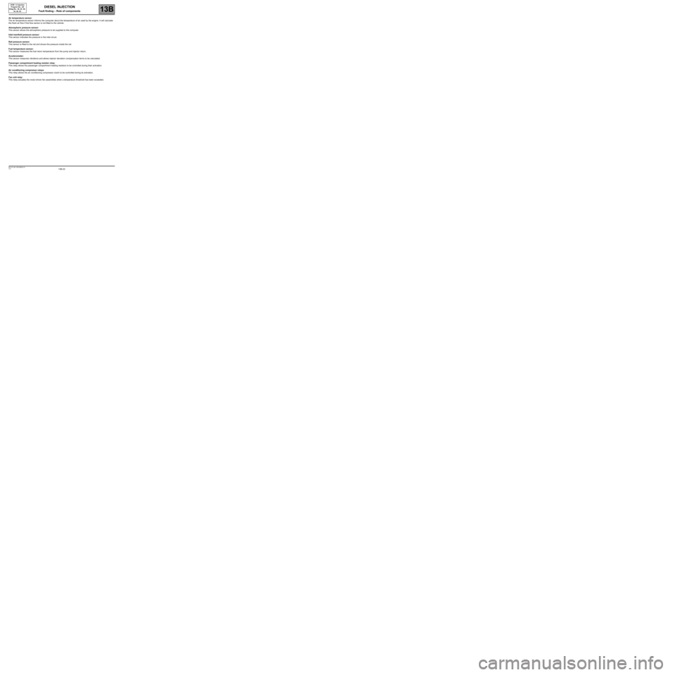
Page 22 of 269
13B-22V10 MR-372-J84-13B100$050.mif
DIESEL INJECTION
Fault finding – Role of components13B
DCM 1.2 Injection
Program No.: 4D
Vdiag No.: 48, 4C, 50,
54, 58, 5C
Air temperature sensor:
The air temperature sensor informs the computer about the temperature of air used by the engine. It will calculate
the fresh air flow if the flow sensor is not fitted to the vehicle.
Atmospheric pressure sensor:
This sensor allows the atmospheric pressure to be supplied to the computer.
Inlet manifold pressure sensor:
This sensor indicates the pressure in the inlet circuit.
Rail pressure sensor:
This sensor is fitted to the rail and shows the pressure inside the rail.
Fuel temperature sensor:
This sensor measures the fuel return temperature from the pump and injector return.
Accelerometer:
This sensor measures vibrations and allows injector deviation compensation terms to be calculated.
Passenger compartment heating resistor relay:
This relay allows the passenger compartment heating resistors to be controlled during their activation.
Air conditioning compressor relays:
This relay allows the air conditioning compressor clutch to be controlled during its activation.
Fan unit relay:
This relay actuates the motor-driven fan assemblies when a temperature threshold has been exceeded.
Page 28 of 269
13B-28V10 MR-372-J84-13B100$080.mif
DIESEL INJECTION
Fault finding – Fault summary table13B
DCM 1.2 Injection
Program No.: 4D
Vdiag No.: 48, 4C, 50,
54, 58, 5C
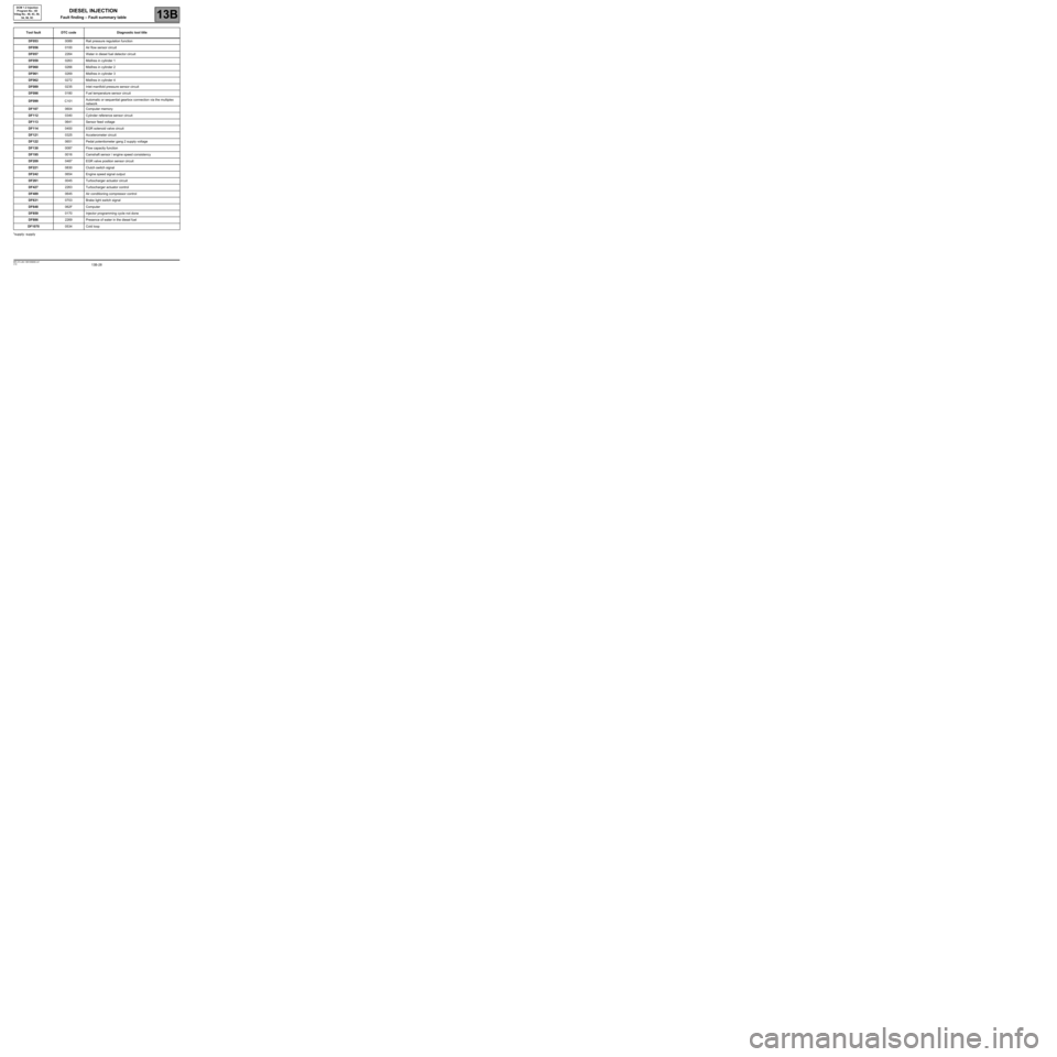
*supply: supplyDF0530089 Rail pressure regulation function
DF0560100 Air flow sensor circuit
DF0572264 Water in diesel fuel detector circuit
DF0590263 Misfires in cylinder 1
DF0600266 Misfires in cylinder 2
DF0610269 Misfires in cylinder 3
DF0620272 Misfires in cylinder 4
DF0890235 Inlet manifold pressure sensor circuit
DF0980180 Fuel temperature sensor circuit
DF099C101Automatic or sequential gearbox connection via the multiplex
network
DF1070604 Computer memory
DF1120340 Cylinder reference sensor circuit
DF1130641 Sensor feed voltage
DF1140400 EGR solenoid valve circuit
DF1210325 Accelerometer circuit
DF1220651 Pedal potentiometer gang 2 supply voltage
DF1300087 Flow capacity function
DF1950016 Camshaft sensor / engine speed consistency
DF2090487 EGR valve position sensor circuit
DF2210830 Clutch switch signal
DF2420654 Engine speed signal output
DF2610045 Turbocharger actuator circuit
DF4272263 Turbocharger actuator control
DF4890645 Air conditioning compressor control
DF6310703 Brake light switch signal
DF648062F Computer
DF8590170 Injector programming cycle not done
DF8862269 Presence of water in the diesel fuel
DF10700534 Cold loop
Tool faultDTC codeDiagnostic tool title
Page 113 of 269
13B-113
AFTER REPAIRDeal with any faults displayed by the diagnostic tool.
Clear the computer fault memory.
Carry out a road test followed by another check with the diagnostic tool.
V10 MR-372-J84-13B100$120.mif
DIESEL INJECTION
Fault finding – Interpretation of faults13B
DCM 1.2 Injection
Program No.: 4D
Vdiag No.: 48, 4C, 50,
54, 58, 5C
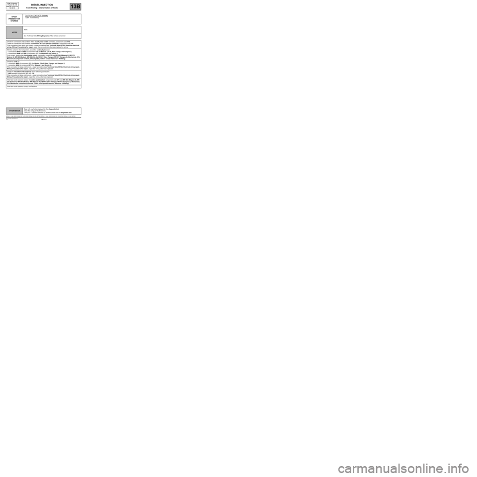
DF221
PRESENT OR
STOREDCLUTCH CONTACT SIGNAL1.DEF: Inconsistency
NOTESNone.
See Technical Note Wiring Diagrams of the vehicle concerned
Check the connection and condition of the clutch pedal switch connector, component code 675.
Check the connection and condition of connector A of the injection computer, component code 120.
If the connector(s) are faulty and there is a repair procedure (see Technical Note 6015A, Repairing electrical
wiring, Wiring: Precautions for repair) repair the connector(s), otherwise replace the wiring.
With the switch in the rest position, check the continuity between:
–connections MAS and 86D of component 675 (for Modus, Clio III, New Twingo, and Kangoo 2).
–connections MAM and 26X of component 675 (for Mégane II and Scénic II).
If not correct, replace the clutch pedal switch, component code 675 (see MR 364 (Mégane II), MR 370
(Scénic II), MR 385 (Modus), MR 392 (Clio III), MR 411 (New Twingo), MR 417 (Kangoo 2), Mechanical, 37A,
Mechanical component controls, Clutch pedal position sensor: Removal - Refitting).
Check for earth on
–connection MAS of component 675 (for Modus, Clio III, New Twingo, and Kangoo 2).
–connection MAM of component 675 (for Mégane II and Scénic II).
If the connection is faulty and there is a repair procedure (see Technical Note 6015A, Electrical wiring repair,
Wiring: Precautions for repair), repair the wiring, otherwise replace it.
Check the insulation and continuity of the following connection:
–86D between components 675 and 120.
If the connection is faulty and there is a repair procedure (see Technical Note 6015A, Electrical wiring repair,
Wiring: Precautions for repair), repair the wiring, otherwise replace it.
If the fault is still present, replace the clutch pedal switch, component code 675 (see MR 364 (Mégane II), MR
370 (Scénic II), MR 385 (Modus), MR 392 (Clio III), MR 411 (New Twingo), MR 417 (Kangoo 2), Mechanical,
37A, Mechanical component controls, Clutch pedal position sensor: Removal - Refitting).
If the fault is still present, contact the Techline.
DCM1.2_V48_DF221/DCM1.2_V4C_DF221/DCM1.2_V50_DF221/DCM1.2_V54_DF221/DCM1.2_V58_DF221/DCM1.2_V5C_DF221
Page 124 of 269
13B-124
AFTER REPAIRDeal with any faults displayed by the diagnostic tool.
Clear the computer fault memory.
Carry out a road test followed by another check with the diagnostic tool.
V10 MR-372-J84-13B100$120.mif
DIESEL INJECTION
Fault finding – Interpretation of faults13B
DCM 1.2 Injection
Program No.: 4D
Vdiag No.: 48, 4C, 50,
54, 58, 5C
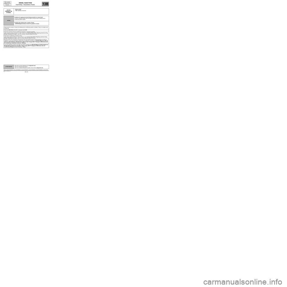
DF1070
PRESENT OR
STOREDCOLD LOOP1.DEF: Jammed component
NOTESConditions for applying the fault finding procedure to a stored fault:
The fault is declared present with the engine running and with a heating and air
conditioning system request.
Priorities when dealing with a number of faults:
–DF049 Refrigerant sensor circuit if it is present or stored.
When the fault is present or stored, the heating and air conditioning system is inhibited. There is no longer any air
conditioning.
Check fuse F22 (10 A) of the UPC, component code 1337.
Check the connector of the air conditioning compressor, component code 171.
If the connector is faulty and there is a repair method (see Technical Note 6015A, Repairing electrical wiring,
Wiring: Precautions for repair), repair the connector, otherwise replace the wiring.
Check the air conditioning compressor wiring.
If the wiring is faulty and there is a repair procedure (see Technical Note 6015A, Repairing electrical wiring,
Wiring: Precautions for repair), repair the wiring, otherwise replace the wiring.
Manually check if the compressor is jammed (turn the clutch plate manually to check that there is no point of
resistance). In the event of jamming, replace the air conditioning compressor (see MR 364 (Mégane II), MR 370
(Scénic II), MR 385 (Modus), MR 392 (Clio III), MR 411 (New Twingo), MR 417 (Kangoo 2), Mechanical, 62A,
Air conditioning, Compressor: Removal - Refitting).
Top up the refrigerant, check for any leaks, and repair if necessary (see MR 364 (Mégane II), MR 370 (Scénic II),
MR 385 (Modus), MR 392 (Clio III), MR 411 (New Twingo), MR 417 (Kangoo 2), Mechanical, 62A, Air
conditioning, Refrigerant circuit: Draining - Filling).
DCM1.2_V48_DF1070/DCM1.2_V4C_DF1070/DCM1.2_V50_DF1070/DCM1.2_V54_DF1070/DCM1.2_V58_DF1070/DCM1.2_V5C_DF1070
Page 126 of 269
13B-126V10 MR-372-J84-13B100$140.mif
13B
DCM 1.2 Injection
Program No.: 4D
Vdiag No.: 48, 4C, 50,
54, 58, 5C
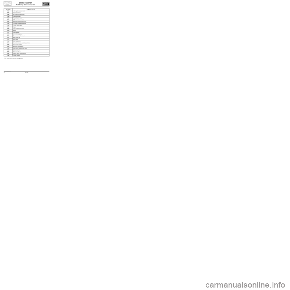
* RCH: Passenger compartment heating resistor.Tool status Diagnostic tool title
ET001+ After ignition computer feed
ET003Engine immobiliser
ET004Air conditioning authorisation
ET006Code programmed
ET007Pre-postheating control
ET008EGR solenoid valve control
ET021High speed fan assembly request
ET022Low speed fan assembly request
ET023Fast idle speed request
ET038Engine
ET042Cruise control/Speed limiter
ET076Starting
ET077Impact detected
ET079Air conditioning present
ET088Compressor actuation request
ET111RCH* number set
ET112RCH* cut-off
ET405Clutch pedal switch
ET415Deactivation of cruise control/speed limiter
ET563Flow capacity function
ET637New pump chamber filling
ET703Cruise control - speed limiter button
ET704Brakecontact No 1
ET705Brakecontact No 2
ET741Optional vehicle speed restriction
ET800Fast idle function
DIESEL INJECTION
Fault finding – Status summary table
Page 152 of 269
13B-152
AFTER REPAIRDeal with any faults. Clear the faults from the computer memory.
Switch off the ignition and carry out a road test followed by a test with the diagnostic
tool.
V10 MR-372-J84-13B100$150.mif
DIESEL INJECTION
Fault finding – Interpretation of statuses13B
DCM 1.2 Injection
Program No.: 4D
Vdiag No.: 48, 4C, 50,
54, 58, 5C
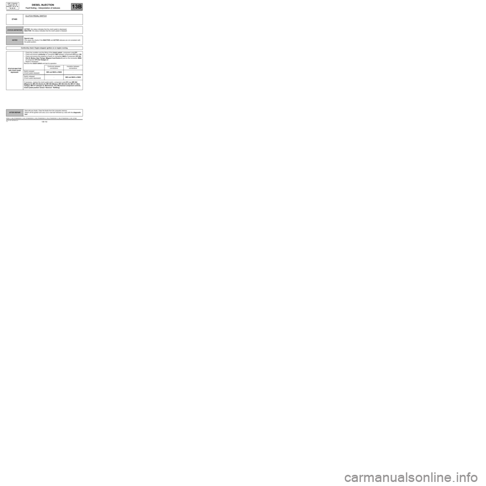
ET405CLUTCH PEDAL SWITCH
STATUS DEFINITIONACTIVE: this status indicates that the clutch pedal is depressed.
INACTIVE: this status indicates that the clutch pedal is released.
NOTESSpecial note:
Only apply the checks if the INACTIVE and ACTIVE statuses are not consistent with
the pedal position.
Conformity check: Engine stopped, ignition on or engine running.
STATUS INACTIVE
with clutch pedal
depressed.–Check the condition and the fitting of the clutch switch, component code 675.
–Check and ensure continuity on connection 86D between components 675 and 120.
–Check and ensure the presence of earth on connection MAS of component 675 (for
Clio III, Modus, New Twingo, Mégane II and Scénic II) and on the connection MAN
of component 675 (for Kangoo 2).
–Repair if necessary.
Remove the clutch switch and test its operation:
Continuity between
connectionsInsulation between
connections
Switch pressed
(Clutch pedal released)86D and MAS or MAN-
Switch released
(Clutch pedal depressed)-86D and MAS or MAN
If necessary, replace the clutch pedal switch, component code 675 (see MR 364
(Mégane II), MR 370 (Scénic II), MR 385 (Modus), MR 392 (Clio III), MR 411 (New
Twingo), MR 417 (Kangoo 2), Mechanical, 37A, Mechanical component controls,
Clutch pedal position sensor: Removal - Refitting).
DCM1.2_V48_ET405/DCM1.2_V4C_ET405/DCM1.2_V50_ET405/DCM1.2_V54_ET405/DCM1.2_V58_ET405/DCM1.2_V5C_ET405