lock RENAULT SCENIC 2010 J95 / 3.G Engine And Pheripherals DCM 1.2 Injection User Guide
[x] Cancel search | Manufacturer: RENAULT, Model Year: 2010, Model line: SCENIC, Model: RENAULT SCENIC 2010 J95 / 3.GPages: 269
Page 64 of 269
13B-64
AFTER REPAIRDeal with any faults displayed by the diagnostic tool.
Clear the computer fault memory.
Carry out a road test followed by another check with the diagnostic tool.
V10 MR-372-J84-13B100$100.mif
DIESEL INJECTION
Fault finding – Interpretation of faults13B
DCM 1.2 Injection
Program No.: 4D
Vdiag No.: 48, 4C, 50,
54, 58, 5C
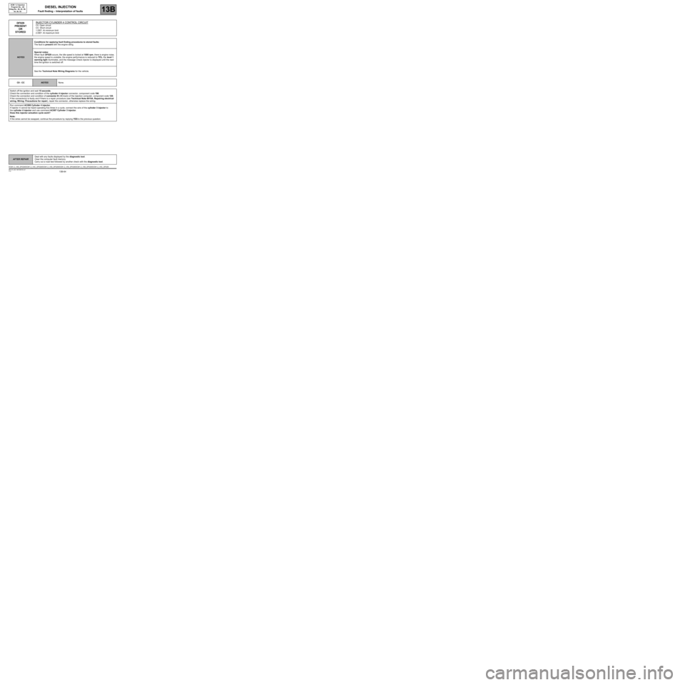
DF029
PRESENT
OR
STOREDINJECTOR CYLINDER 4 CONTROL CIRCUITC0: Open circuit
CC: Short circuit
1.DEF: At minimum limit
2.DEF: At maximum limit
NOTESConditions for applying fault finding procedures to stored faults:
The fault is present with the engine idling.
Special notes:
When fault DF029 occurs, the idle speed is locked at 1000 rpm, there is engine noise,
the engine speed is unstable, the engine performance is reduced to 75%, the level 1
warning light illuminates, and the message Check injector is displayed until the next
time the ignition is switched off.
See the Technical Note Wiring Diagrams for the vehicle.
C0 - CC
NOTESNone.
Switch off the ignition and wait 15 seconds.
Check the connection and condition of the cylinder 4 injector connector, component code 196.
Check the connection and condition of connector B (48-track) of the injection computer, component code 120.
If the connector(s) is faulty and if there is a repair procedure (see Technical Note 6015A, Repairing electrical
wiring, Wiring: Precautions for repair), repair the connector, otherwise replace the wiring.
Run command AC008 Cylinder 4 injector.
If injector 4 cannot be heard operating five times in a cycle, connect the wire of the cylinder 3 injector to
the cylinder 4 injector and use command AC007 Cylinder 3 injector.
Does this injector actuation cycle work?
Note:
If the wires cannot be swapped, continue the procedure by replying YES to the previous question.
DCM1.2_V48_DF029/DCM1.2_V4C_DF029/DCM1.2_V50_DF029/DCM1.2_V54_DF029/DCM1.2_V58_DF029/DCM1.2_V5C_DF029
Page 72 of 269
13B-72
AFTER REPAIRDeal with any faults displayed by the diagnostic tool.
Clear the computer fault memory.
Carry out a road test followed by another check with the diagnostic tool.
V10 MR-372-J84-13B100$100.mif
DIESEL INJECTION
Fault finding – Interpretation of faults13B
DCM 1.2 Injection
Program No.: 4D
Vdiag No.: 48, 4C, 50,
54, 58, 5C
* C2I: Individual injector correction
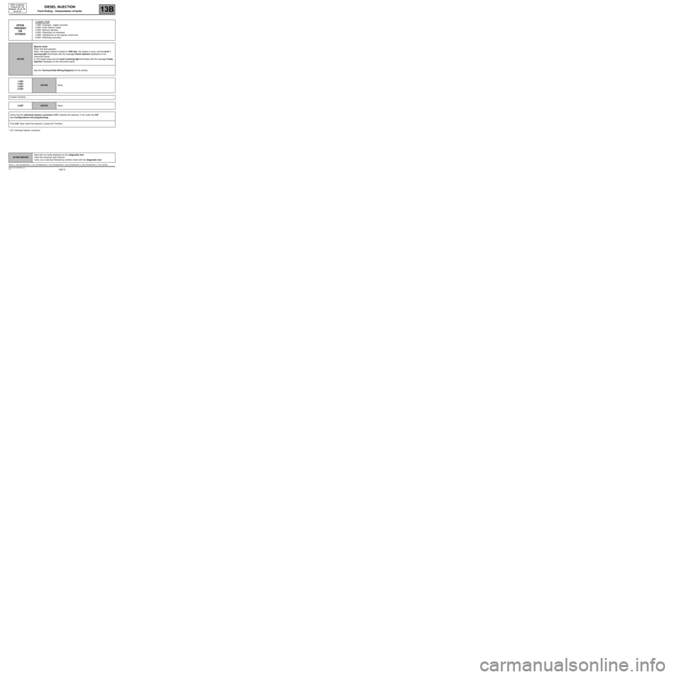
DF038
PRESENT
OR
STOREDCOMPUTER1.DEF: Analogue - digital converter
2.DEF: Enter injector codes
3.DEF: Memory self-test
4.DEF: Watchdog not refreshed
5.DEF: Interference on the injector control line
6.DEF: Watchdog activation
NOTESSpecial notes:
When this fault appears:
either: the engine speed is locked at 1300 rpm, the engine is noisy, and the level 1
warning light illuminates with the message Check injection displayed on the
instrument panel,
or: the engine stops and the level 2 warning light illuminates with the message Faulty
injection displayed on the instrument panel.
See the Technical Note Wiring Diagrams for the vehicle.
1.DEF
3.DEF
4.DEF
6.DEF
NOTESNone.
Contact Techline.
2.DEF
NOTESNone.
Check that the individual injector correction (C2I*) matches the injectors; if not, enter the C2I*
(see Configurations and programming).
If the C2I* does match the injectors, contact the Techline.
DCM1.2_V48_DF038/DCM1.2_V4C_DF038/DCM1.2_V50_DF038/DCM1.2_V54_DF038/DCM1.2_V58_DF038/DCM1.2_V5C_DF038
Page 76 of 269
13B-76
AFTER REPAIRDeal with any faults displayed by the diagnostic tool.
Clear the computer fault memory.
Carry out a road test followed by another check with the diagnostic tool.
V10 MR-372-J84-13B100$110.mif
DIESEL INJECTION
Fault finding – Interpretation of faults13B
DCM 1.2 Injection
Program No.: 4D
Vdiag No.: 48, 4C, 50,
54, 58, 5C
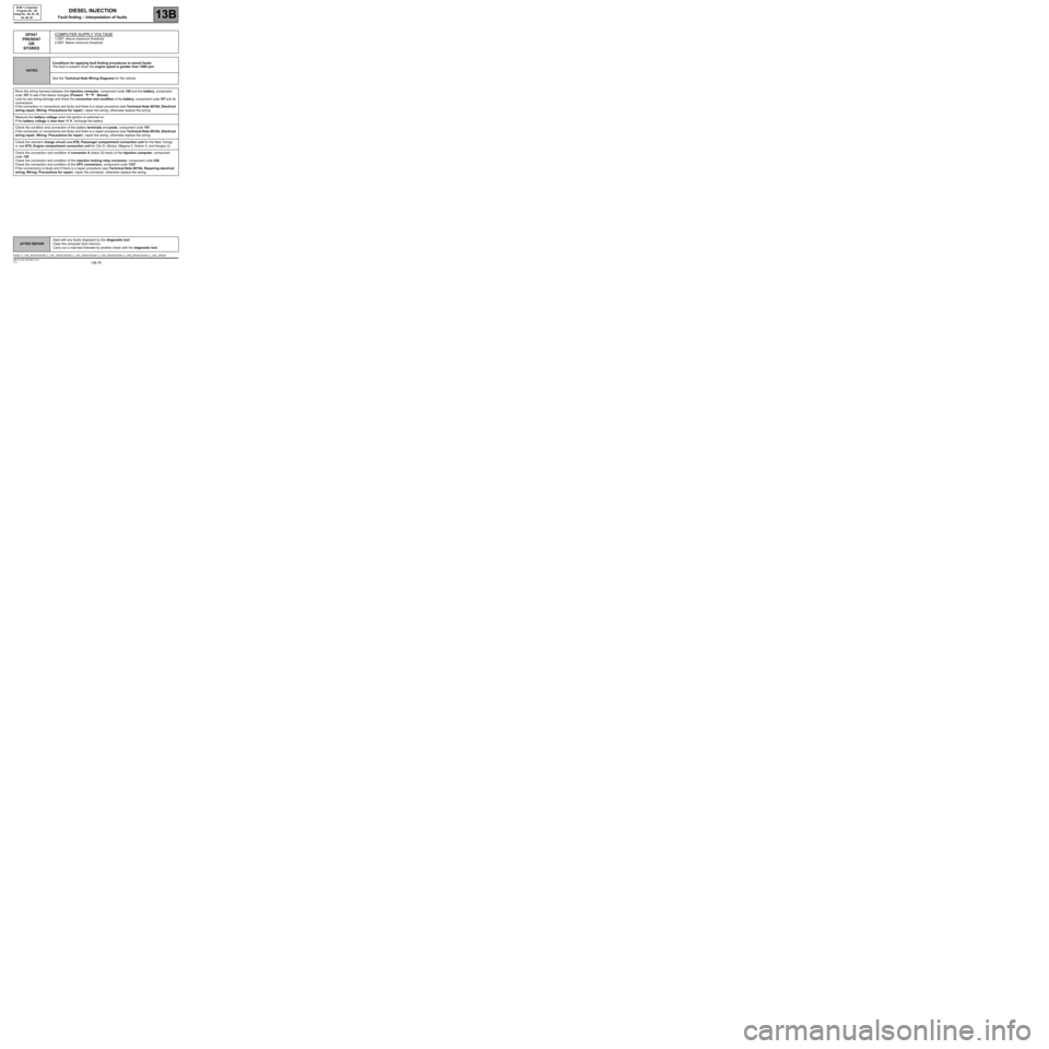
DF047
PRESENT
OR
STOREDCOMPUTER SUPPLY VOLTAGE
1.DEF: Above maximum threshold
2.DEF: Below minimum threshold
NOTESConditions for applying fault finding procedures to stored faults:
The fault is present when the engine speed is greater than 1000 rpm.
See the Technical Note Wiring Diagrams for the vehicle.
Move the wiring harness between the injection computer, component code 120 and the battery, component
code 107 to see if the status changes (Present Stored).
Look for any wiring damage and check the connection and condition of the battery, component code 107 and its
connections.
If the connection or connections are faulty and there is a repair procedure (see Technical Note 6015A, Electrical
wiring repair, Wiring: Precautions for repair), repair the wiring, otherwise replace the wiring.
Measure the battery voltage when the ignition is switched on.
If the battery voltage is less than 11 V, recharge the battery.
Check the condition and connection of the battery terminals and posts, component code 107.
If the connection or connections are faulty and there is a repair procedure (see Technical Note 6015A, Electrical
wiring repair, Wiring: Precautions for repair), repair the wiring, otherwise replace the wiring.
Check the vehicle's charge circuit (see 87B, Passenger compartment connection unit for the New Twingo
or see 87G, Engine compartment connection unit for Clio III, Modus, Mégane II, Scénic II, and Kangoo 2).
Check the connection and condition of connector A (black 32-track) of the injection computer, component
code 120.
Check the connection and condition of the injection locking relay connector, component code 238.
Check the connection and condition of the UPC connectors, component code 1337.
If the connector(s) is faulty and if there is a repair procedure (see Technical Note 6015A, Repairing electrical
wiring, Wiring: Precautions for repair), repair the connector, otherwise replace the wiring.
DCM1.2_V48_DF047/DCM1.2_V4C_DF047/DCM1.2_V50_DF047/DCM1.2_V54_DF047/DCM1.2_V58_DF047/DCM1.2_V5C_DF047
Page 80 of 269
13B-80
AFTER REPAIRDeal with any faults displayed by the diagnostic tool.
Clear the computer fault memory.
Carry out a road test followed by another check with the diagnostic tool.
V10 MR-372-J84-13B100$110.mif
DIESEL INJECTION
Fault finding – Interpretation of faults13B
DCM 1.2 Injection
Program No.: 4D
Vdiag No.: 48, 4C, 50,
54, 58, 5C
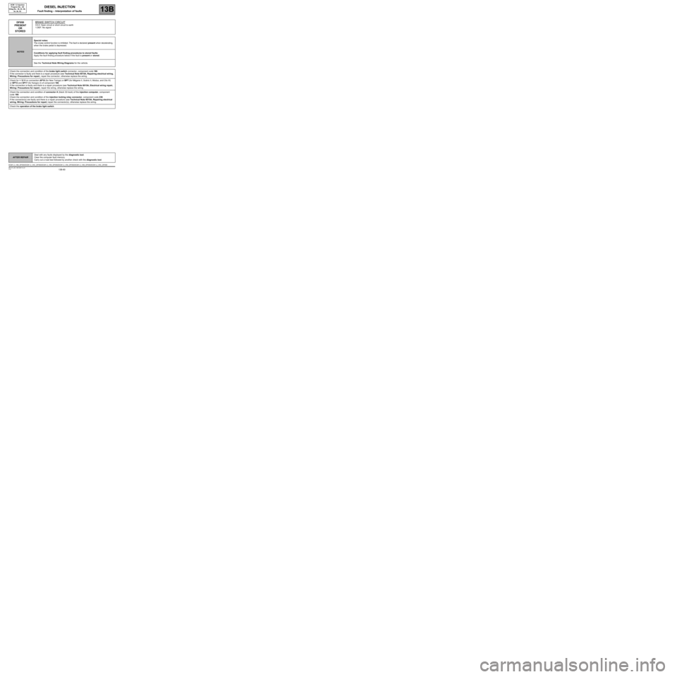
DF050
PRESENT
OR
STOREDBRAKE SWITCH CIRCUIT
C0.0: Open circuit or short circuit to earth
1.DEF: No signal
NOTESSpecial notes:
The cruise control function is inhibited. The fault is declared present when decelerating,
when the brake pedal is depressed.
Conditions for applying fault finding procedures to stored faults:
Apply the fault finding procedure below if the fault is present or stored.
See the Technical Note Wiring Diagrams for the vehicle.
Check the connection and condition of the brake light switch connector, component code 160.
If the connector is faulty and there is a repair procedure (see Technical Note 6015A, Repairing electrical wiring,
Wiring: Precautions for repair), repair the connector, otherwise replace the wiring.
Check for + 12 V on connection AP10 (for New Twingo) or BPT (for Mégane II, Scénic II, Modus, and Clio III)
or BPT2 and SP17 (for Kangoo 2) of component 160.
If the connection is faulty and there is a repair procedure (see Technical Note 6015A, Electrical wiring repair,
Wiring: Precautions for repair), repair the wiring, otherwise replace the wiring.
Check the connection and condition of connector A (black 32-track) of the injection computer, component
code 160.
Check the connection and condition of the injection locking relay connector, component code 238.
If the connector(s) are faulty and there is a repair procedure (see Technical Note 6015A, Repairing electrical
wiring, Wiring: Precautions for repair) repair the connector(s), otherwise replace the wiring.
Check the operation of the brake light switch.
DCM1.2_V48_DF050/DCM1.2_V4C_DF050/DCM1.2_V50_DF050/DCM1.2_V54_DF050/DCM1.2_V58_DF050/DCM1.2_V5C_DF050
Page 87 of 269
13B-87
AFTER REPAIRDeal with any faults displayed by the diagnostic tool.
Clear the computer fault memory.
Carry out a road test followed by another check with the diagnostic tool.
V10 MR-372-J84-13B100$110.mif
DIESEL INJECTION
Fault finding – Interpretation of faults13B
DCM 1.2 Injection
Program No.: 4D
Vdiag No.: 48, 4C, 50,
54, 58, 5C
DF056
PRESENT
OR
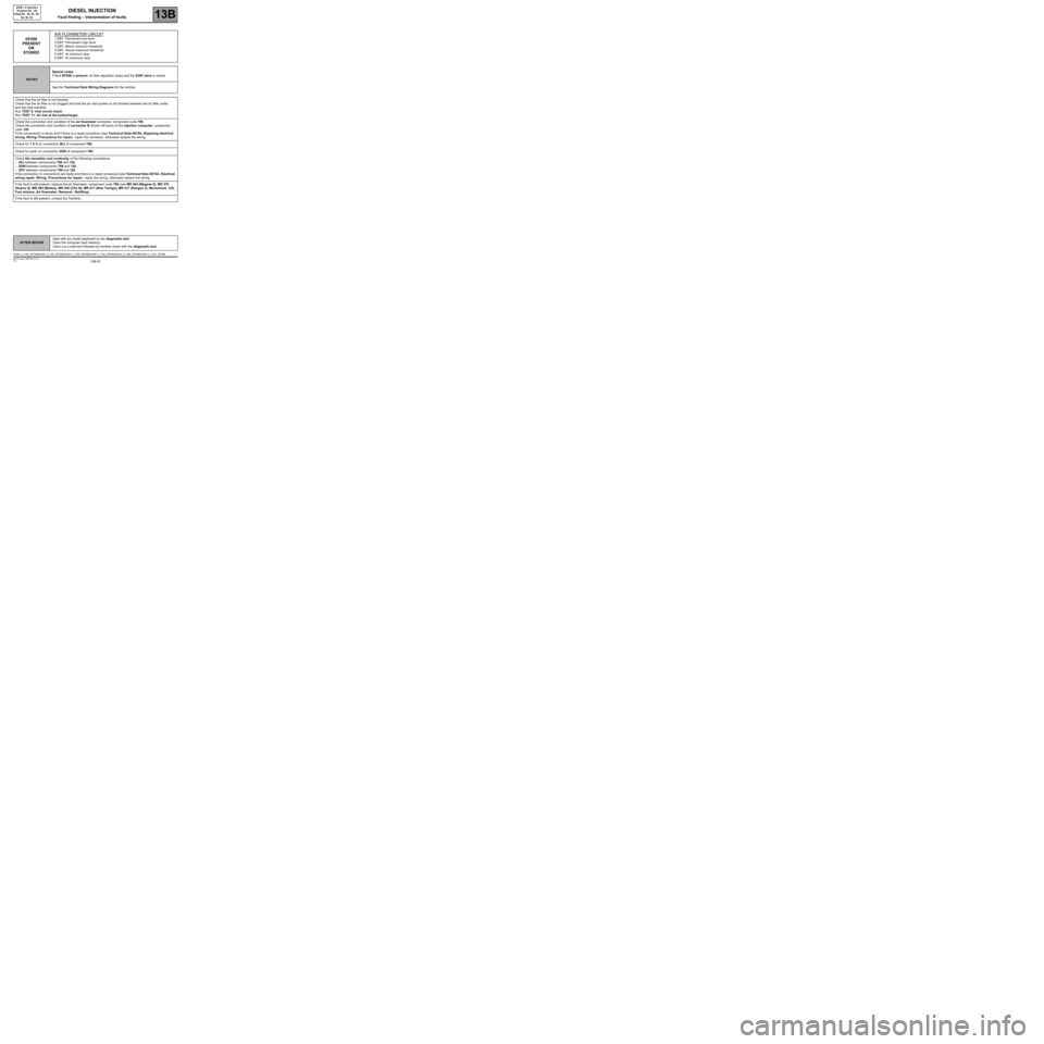
STOREDAIR FLOWMETER CIRCUIT1.DEF: Permanent low level
2.DEF: Permanent high level
3.DEF: Below minimum threshold
4.DEF: Above maximum threshold
5.DEF: At minimum stop
6.DEF: At maximum stop
NOTESSpecial notes:
If fault DF056 is present: air flow regulation stops and the EGR valve is closed.
See the Technical Note Wiring Diagrams for the vehicle.
Check that the air filter is not blocked.
Check that the air filter is not clogged and that the air inlet system is not blocked between the air filter outlet
and the inlet manifold.
Run TEST 5: Inlet circuit check.
Run TEST 11: Air line at the turbocharger.
Check the connection and condition of the air flowmeter connector, component code 799.
Check the connection and condition of connector B (brown 48-track) of the injection computer, component
code 120.
If the connector(s) is faulty and if there is a repair procedure (see Technical Note 6015A, Repairing electrical
wiring, Wiring: Precautions for repair), repair the connector, otherwise replace the wiring.
Check for + 5 V on connection 3KJ of component 799.
Check for earth on connection 3DW of component 799.
Check the insulation and continuity of the following connections:
–3KJ between components 799 and 120,
–3DW between components 799 and 120,
–3DV between components 799 and 120.
If the connection or connections are faulty and there is a repair procedure (see Technical Note 6015A, Electrical
wiring repair, Wiring: Precautions for repair), repair the wiring, otherwise replace the wiring.
If the fault is still present, replace the air flowmeter, component code 799 (see MR 364 (Mégane II), MR 370
(Scénic II), MR 385 (Modus), MR 392 (Clio III), MR 411 (New Twingo), MR 417 (Kangoo 2), Mechanical, 12A,
Fuel mixture, Air flowmeter: Removal - Refitting).
If the fault is still present, contact the Techline.
DCM1.2_V48_DF056/DCM1.2_V4C_DF056/DCM1.2_V50_DF056/DCM1.2_V54_DF056/DCM1.2_V58_DF056/DCM1.2_V5C_DF056
Page 95 of 269
13B-95
AFTER REPAIRDeal with any faults displayed by the diagnostic tool.
Clear the computer fault memory.
Carry out a road test followed by another check with the diagnostic tool.
V10 MR-372-J84-13B100$110.mif
DIESEL INJECTION
Fault finding – Interpretation of faults13B
DCM 1.2 Injection
Program No.: 4D
Vdiag No.: 48, 4C, 50,
54, 58, 5C
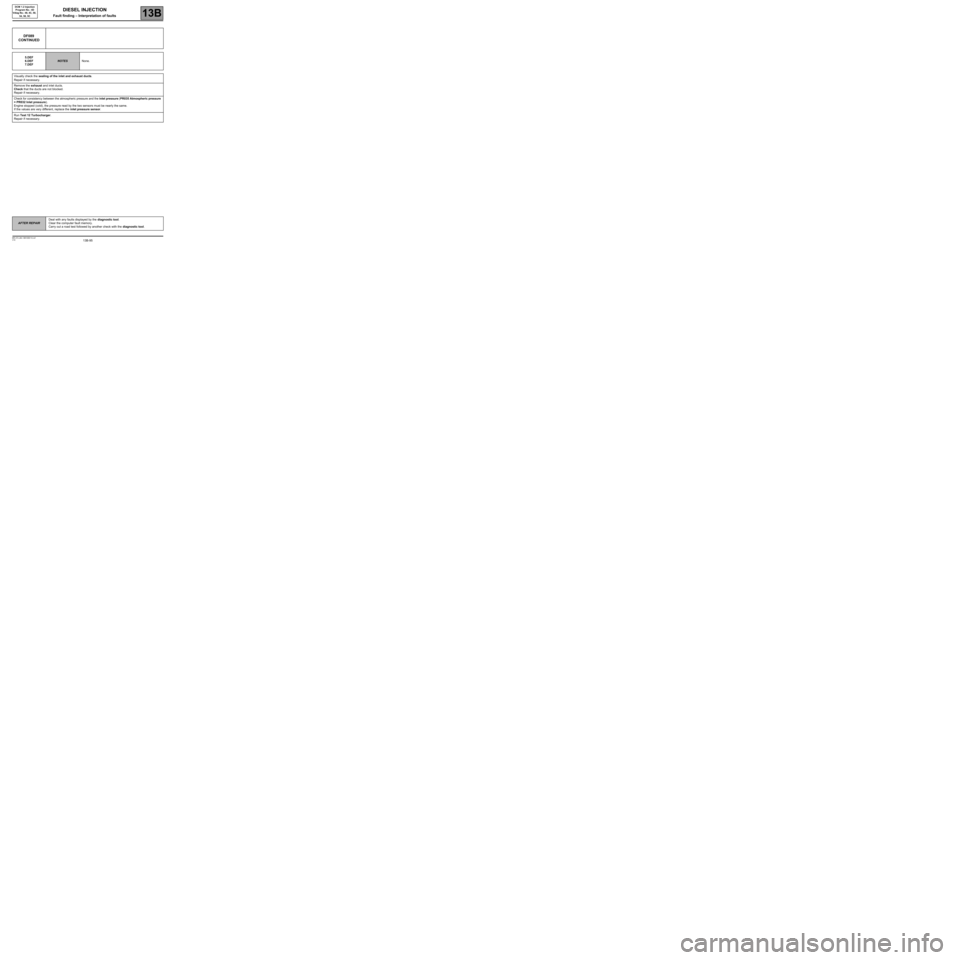
DF089
CONTINUED
5.DEF
6.DEF
7.DEF
NOTESNone.
Visually check the sealing of the inlet and exhaust ducts.
Repair if necessary.
Remove the exhaust and inlet ducts.
Check that the ducts are not blocked.
Repair if necessary.
Check for consistency between the atmospheric pressure and the inlet pressure (PR035 Atmospheric pressure
= PR032 Inlet pressure).
Engine stopped (cold), the pressure read by the two sensors must be nearly the same.
If the values are very different, replace the inlet pressure sensor.
Run Test 12 Turbocharger.
Repair if necessary.
Page 99 of 269
13B-99
AFTER REPAIRDeal with any faults displayed by the diagnostic tool.
Clear the computer fault memory.
Carry out a road test followed by another check with the diagnostic tool.
V10 MR-372-J84-13B100$110.mif
DIESEL INJECTION
Fault finding – Interpretation of faults13B
DCM 1.2 Injection
Program No.: 4D
Vdiag No.: 48, 4C, 50,
54, 58, 5C
DF112
PRESENT
OR
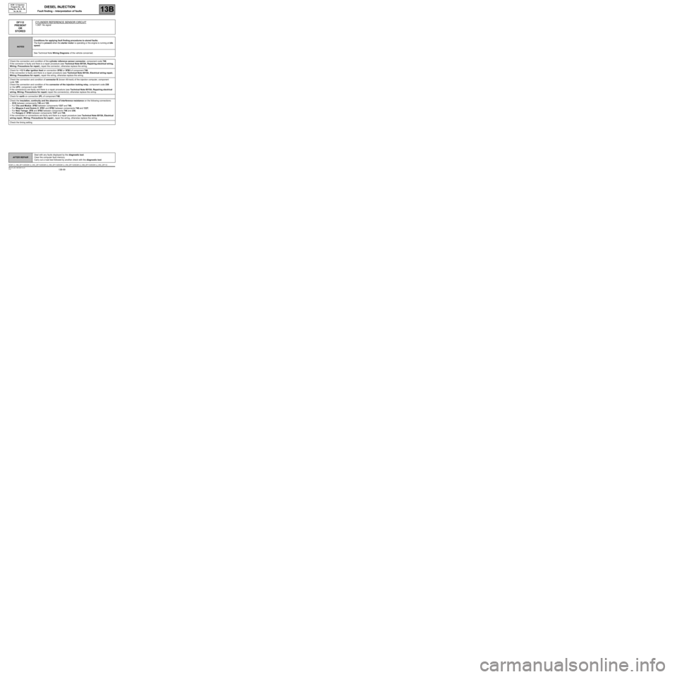
STOREDCYLINDER REFERENCE SENSOR CIRCUIT
1.DEF: No signal
NOTESConditions for applying fault finding procedures to stored faults:
The fault is present when the starter motor is operating or the engine is running at idle
speed.
See Technical Note Wiring Diagrams of the vehicle concerned.
Check the connection and condition of the cylinder reference sensor connector, component code 746.
If the connector is faulty and there is a repair procedure (see Technical Note 6015A, Repairing electrical wiring,
Wiring: Precautions for repair), repair the connector, otherwise replace the wiring.
Check for +12 V after ignition feed on connection 3FB2 or 3FB3 of component 746.
If the connection is faulty and there is a repair procedure (see Technical Note 6015A, Electrical wiring repair,
Wiring: Precautions for repair), repair the wiring, otherwise replace the wiring.
Check the connection and condition of connector B (brown 48-track) of the injection computer, component
code 120.
Check the connection and condition of the connector of the injection locking relay, component code 238
or the UPC, component code 1337.
If the connector(s) are faulty and there is a repair procedure (see Technical Note 6015A, Repairing electrical
wiring, Wiring: Precautions for repair) repair the connector(s), otherwise replace the wiring.
Check for earth on connection 3PL of component 746.
Check the insulation, continuity and the absence of interference resistance on the following connections:
–3CQ between components 746 and 120,
–For Clio and Modus: 3FB2 between components 1337 and 746,
–For Mégane II and Scénic II: 3FB1 and 3FB2 between components 746 and 1337,
–For New Twingo: 3FB and 3FB2 between components 746 and 238,
–For Kangoo 2: 3FB3 between components 1337 and 746.
If the connection or connections are faulty and there is a repair procedure (see Technical Note 6015A, Electrical
wiring repair, Wiring: Precautions for repair), repair the wiring, otherwise replace the wiring.
Check the timing setting.
DCM1.2_V48_DF112/DCM1.2_V4C_DF112/DCM1.2_V50_DF112/DCM1.2_V54_DF112/DCM1.2_V58_DF112/DCM1.2_V5C_DF112
Page 108 of 269
13B-108
AFTER REPAIRDeal with any faults displayed by the diagnostic tool.
Clear the computer fault memory.
Carry out a road test followed by another check with the diagnostic tool.
V10 MR-372-J84-13B100$120.mif
DIESEL INJECTION
Fault finding – Interpretation of faults13B
DCM 1.2 Injection
Program No.: 4D
Vdiag No.: 48, 4C, 50,
54, 58, 5C
DF122
PRESENT OR
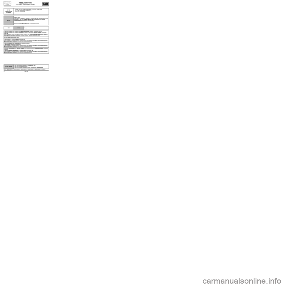
STOREDPEDAL POTENTIOMETER GANG 2 SUPPLY VOLTAGECO.1: open circuit or short circuit to +12 V.
CC.0: short circuit to earth.
NOTESSpecial notes:
If fault DF122 is present: the idle speed is locked at 1000 rpm, the engine performance
is reduced to 75%, and the level 1 warning light illuminates with the message
Check injection displayed on the instrument panel.
See Technical Note Wiring Diagrams of the vehicle concerned
CC.0
NOTESNone.
Check the connection and condition of the pedal potentiometer connector, component code 921.
Check the connection and condition of connector A (black 32-track) of the injection computer, component
code 120.
If the connector(s) is faulty and if there is a repair procedure (see Technical Note 6015A, Repairing electrical
wiring, Wiring: Precautions for repair), repair the connector, otherwise replace the wiring.
Run test 14 Accelerator pedal check.
Check for earth on connection 3LV of component 921.
If the connection is faulty and there is a repair procedure (see Technical Note 6015A, Electrical wiring repair,
Wiring: Precautions for repair), repair the wiring, otherwise replace it.
Check the insulation and continuity of the following connection:
–3LU between components 921 and 120.
If the connection is faulty and there is a repair procedure (see Technical Note 6015A, Electrical wiring repair,
Wiring: Precautions for repair), repair the wiring, otherwise replace it.
Disconnect connector A of the injection computer and the connector of the pedal potentiometer, component
code 921.
Check the insulation against earth of connection 3LU of component 120.
If the connection is faulty and there is a repair procedure (see Technical Note 6015A, Electrical wiring repair,
Wiring: Precautions for repair), repair the wiring, otherwise replace it.
DCM1.2_V48_DF122/DCM1.2_V4C_DF122/DCM1.2_V50_DF122/DCM1.2_V54_DF122/DCM1.2_V58_DF122/DCM1.2_V5C_DF122
Page 111 of 269
13B-111
AFTER REPAIRDeal with any faults displayed by the diagnostic tool.
Clear the computer fault memory.
Carry out a road test followed by another check with the diagnostic tool.
V10 MR-372-J84-13B100$120.mif
DIESEL INJECTION
Fault finding – Interpretation of faults13B
DCM 1.2 Injection
Program No.: 4D
Vdiag No.: 48, 4C, 50,
54, 58, 5C
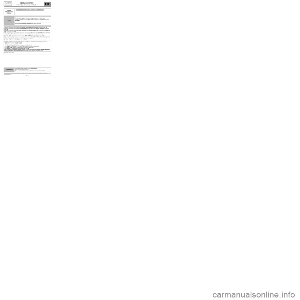
DF195
PRESENT OR
STOREDENGINE SPEED/CAMSHAFT SENSOR CONSISTENCY
NOTESConditions for applying the fault finding procedure to a stored fault:
The fault is present when the starter motor is operating or the engine is running at
idle speed.
See Technical Note Wiring Diagrams of the vehicle concerned
Check the connection and condition of the cylinder reference sensor connector, component code 746.
Check the connection and condition of connector B (brown 48-track) of the injection computer, component
code 120.
Check the connection and condition of the connector of the injection locking relay, component code 238 or the
UPC, component code 1337.
If the connector(s) are faulty and there is a repair procedure (see Technical Note 6015A, Repairing electrical
wiring, Wiring: Precautions for repair) repair the connector(s), otherwise replace the wiring.
Check for +12 V after ignition feed on connection 3FB2 or 3FB3 (for Kangoo 2) of component 746.
If the connection is faulty and there is a repair procedure (see Technical Note 6015A, Electrical wiring repair,
Wiring: Precautions for repair), repair the wiring, otherwise replace it.
Check for earth on connection 3PL of component 746.
Check the insulation, continuity and the absence of interference resistance on the following connections:
–3CQ between components 746 and 120,
–3PL between components 746 and 120,
–For Clio and Modus: 3FB2 between components 1337 and 746,
–For Mégane II and Scénic II: 3FB1 and 3FB2 between components 746 and 1337,
–For New Twingo: 3FB and 3FB2 between components 746 and 238,
–For Kangoo 2: 3FB3 between components 1337 and 746.
If the connection or connections are faulty and there is a repair procedure (see Technical Note 6015A, Electrical
wiring repair, Wiring: Precautions for repair), repair the wiring, otherwise replace the wiring.
Check the timing setting.
DCM1.2_V48_DF195/DCM1.2_V4C_DF195/DCM1.2_V50_DF195/DCM1.2_V54_DF195/DCM1.2_V58_DF195/DCM1.2_V5C_DF195
Page 120 of 269
13B-120
AFTER REPAIRDeal with any faults displayed by the diagnostic tool.
Clear the computer fault memory.
Carry out a road test followed by another check with the diagnostic tool.
V10 MR-372-J84-13B100$120.mif
DIESEL INJECTION
Fault finding – Interpretation of faults13B
DCM 1.2 Injection
Program No.: 4D
Vdiag No.: 48, 4C, 50,
54, 58, 5C
DF648
PRESENT OR
STOREDCOMPUTER1.DEF: Enter EEPROM memory
2.DEF: Read EEPROM memory
NOTESSpecial notes:
When this fault appears:
the engine speed is locked at 1300 rpm, the engine is noisy, and the level 1 warning
light illuminates with the message Check injection displayed on the instrument panel,
Contact Techline.
DCM1.2_V48_DF648/DCM1.2_V4C_DF648/DCM1.2_V50_DF648/DCM1.2_V54_DF648/DCM1.2_V58_DF648/DCM1.2_V5C_DF648