change time RENAULT SCENIC 2010 J95 / 3.G Engine And Pheripherals DCM 1.2 Injection Workshop Manual
[x] Cancel search | Manufacturer: RENAULT, Model Year: 2010, Model line: SCENIC, Model: RENAULT SCENIC 2010 J95 / 3.GPages: 269
Page 5 of 269
13B-5V10 MR-372-J84-13B100$010.mif
DIESEL INJECTION
Fault finding – Introduction13B
DCM 1.2 Injection
Program No.: 4D
Vdiag No.: 48, 4C, 50,
54, 58, 5C
4. FAULT FINDING PROCEDURE (continued)
4.1 Wiring check
Fault finding problems
Disconnecting the connectors and/or handling the wiring harness may temporarily remove, the cause of a fault.
Visual inspection
Look for damage under the bonnet and in the passenger compartment.
Carefully check the protectors, insulation, and routing of the wiring, as well as the mountings.
Physical inspection
While manipulating the wiring, use either the diagnostic tool to detect a change in status from "stored" to "present",
or use the multimeter to view the status changes.
Make sure that the connectors are properly locked.
Apply light pressure to the connectors.
Twist the wiring harness.
Checking earth insulation
This check is carried out by measuring the voltage (multimeter in voltmeter mode) between the suspect connection
and the 12 V or 5 V. The correct measured value is 0 V.
Checking insulation against + 12 V or + 5 V
This check is carried out by measuring the voltage (multimeter in voltmeter mode) between the suspect connection
and the earth. In the first instance, the earth may be taken on the chassis. The correct measured value should
be 0 V.
Continuity check
A continuity check is carried out by measuring the resistance (multimeter in ohmmeter mode), with the connectors
disconnected at both ends. The expected result is: 1 Ω ± 1 Ω for each connection. The line must be fully checked,
and the intermediate connections are only included in the method if this saves time during the fault finding
procedure. The continuity check on the multiplex lines must be carried out on both wires. The measured value
should be 1 Ω ± 1 Ω
Checking the supply
This check may be carried out using a test light (21 W or 5 W depending on the maximum authorised load).
Page 15 of 269
13B-15V10 MR-372-J84-13B100$040.mif
DIESEL INJECTION
Fault finding – Function13B
DCM 1.2 Injection
Program No.: 4D
Vdiag No.: 48, 4C, 50,
54, 58, 5C
Angular position measurement
Engine speed sensor:
The angular position is measured using a magneto-inductive sensor triggered by machined teeth on the shaft
flywheel. This flywheel has sixty teeth, six degrees apart, minus two missing teeth that form a notch.
Cylinder reference sensor:
A second sensor (Hall effect) triggered by a machined tooth on the high pressure pump drive pulley (synchronised
with the camshaft), turning at half the engine speed, supplies a signal about the progress of the injection cycle.
By comparing the signals from these two sensors, the computer's APS module (Angular Position Subsystem) can
supply the entire system with the synchronisation factors, which are: the angular position of the flywheel, the engine
speed, the number of the active injector and the injection cycle timing.
This module also supplies the system with the engine speed signal.
New pump chamber filling procedure (pump boosting)
The pump lubrication goes through a booster cycle during which the pump is filled and pressurised before
"transferring" the diesel fuel to the rail.
This lubrication goes through a procedure called new pump chamber filling, which prevents starting for
approximately 10 seconds, which is the time required for filling the pump and starting. For vehicles with keys,
if the key is released before the end of this "initial starting" phase there is no need for a power latch phase to be
completed before a fresh attempt to start the vehicle.
This procedure is run after the first start in the factory, after a computer is replaced if the parameters relating to
the rail pressure have not been copied into the new computer, and also after reprogramming of the injection
computer.
Variable Low Capacity (VLC) output function
Because of the combination of several parameters such as the diesel fuel temperature, part wear, clogging of
the diesel filter etc., the system limit may be reached during its service life. If this happens, the rail pressure cannot
be maintained because the pump lacks the necessary capacity. If the pump lacks the necessary capacity, this
programming will therefore reduce the requested flow to a value that will enable the pressure monitoring system to
control the pressure again.
The customer may have noticed a loss of vehicle performance when this program is activated (depending on
the vehicle, this programming can be confirmed by ET563 Flow capacity function). This is normal operation of
the injection system.
Function: Air flow management
EGR valve control
K9K 766 and 768 (Euro 4) engines (fitted on Clio III and Modus) and K9K 724 (Euro 4) engines (fitted on
Mégane II and Scénic II) and K9K 740 engines (fitted on New Twingo) and K9K 800, 802 and 812 engines
(fitted on Kangoo 2):
The EGR (Exhaust Gas Recirculation) system consists of a DC proportional EGR valve, which incorporates
a valve position feedback potentiometer. The EGR valve is closed-loop controlled based on its position via
the potentiometer and/or based on changes in the estimated air flow.
K9K 750 and 752 (Euro 3) engines (fitted on Clio III and Modus):
The EGR system (Exhaust Gas Recirculation) consists of an EGR solenoid valve, which incorporates a valve
position feedback potentiometer. The EGR valve is closed-loop controlled based on its position via
the potentiometer and/or based on changes in the estimated air flow.
Page 26 of 269
13B-26V10 MR-372-J84-13B100$070.mif
13B
DCM 1.2 Injection
Program No.: 4D
Vdiag No.: 48, 4C, 50,
54, 58, 5C
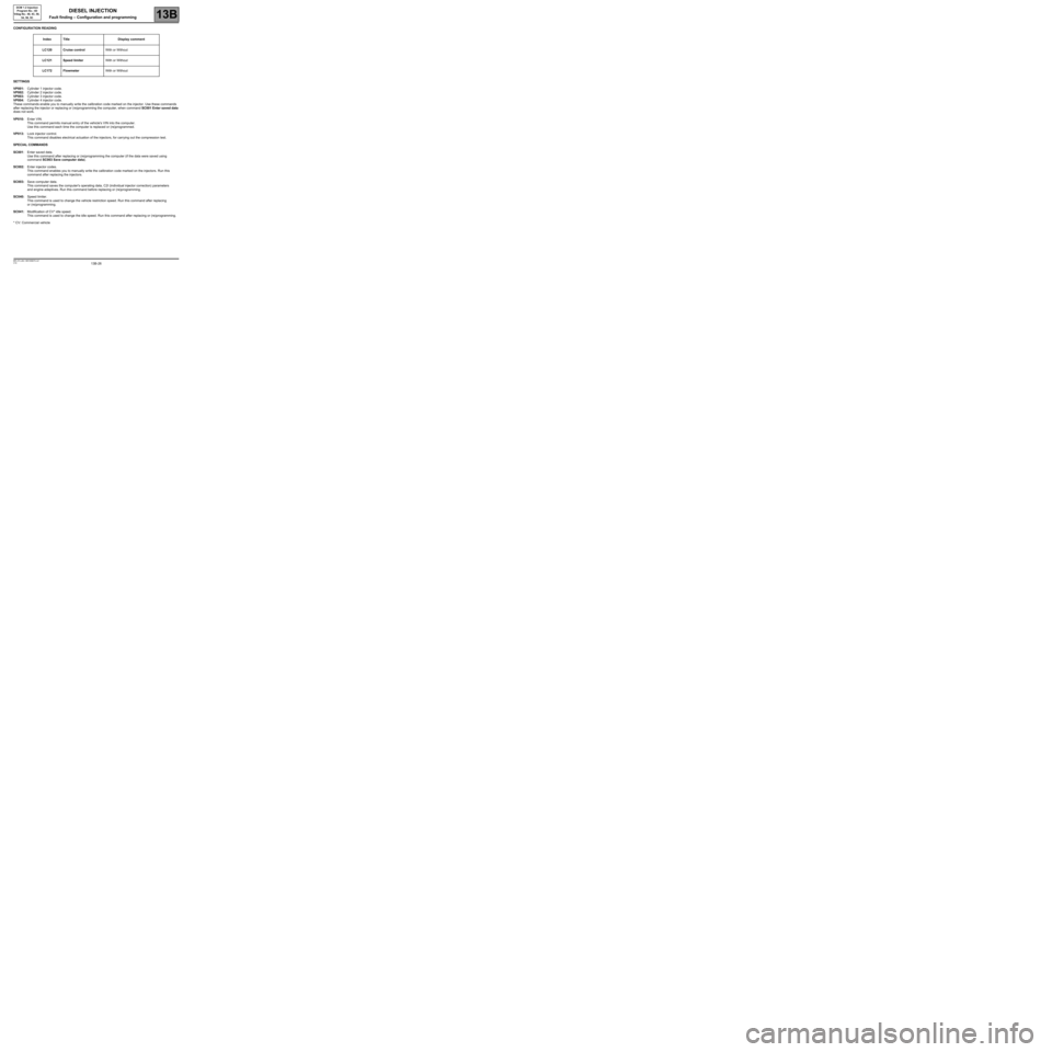
CONFIGURATION READING
SETTINGS
VP001:Cylinder 1 injector code.
VP002:Cylinder 2 injector code.
VP003:Cylinder 3 injector code.
VP004:Cylinder 4 injector code.
These commands enable you to manually write the calibration code marked on the injector. Use these commands
after replacing the injector or replacing or (re)programming the computer, when command SC001 Enter saved data
does not work.
VP010:Enter VIN.
This command permits manual entry of the vehicle's VIN into the computer.
Use this command each time the computer is replaced or (re)programmed.
VP013:Lock injector control.
This command disables electrical actuation of the injectors, for carrying out the compression test.
SPECIAL COMMANDS
SC001:Enter saved data.
Use this command after replacing or (re)programming the computer (if the data were saved using
command SC003 Save computer data).
SC002:Enter injector codes.
This command enables you to manually write the calibration code marked on the injectors. Run this
command after replacing the injectors.
SC003:Save computer data.
This command saves the computer's operating data, C2I (individual injector correction) parameters
and engine adaptives. Run this command before replacing or (re)programming.
SC040:Speed limiter.
This command is used to change the vehicle restriction speed. Run this command after replacing
or (re)programming.
SC041:Modification of CV* idle speed.
This command is used to change the idle speed. Run this command after replacing or (re)programming.
* CV: Commercial vehicleIndex Title Display comment
LC120 Cruise controlWith or Without
LC121 Speed limiterWith or Without
LC172 FlowmeterWith or Without
DIESEL INJECTION
Fault finding – Configuration and programming
Page 128 of 269
13B-128
AFTER REPAIRCarry out another fault finding check on the system.
Deal with any other faults.
Clear the stored faults.
V10 MR-372-J84-13B100$150.mif
DIESEL INJECTION
Fault finding – Interpretation of statuses13B
DCM 1.2 Injection
Program No.: 4D
Vdiag No.: 48, 4C, 50,
54, 58, 5C
ET003ENGINE IMMOBILISER
STATUS DEFINITIONACTIVE: This status indicates that the immobiliser is active.
INACTIVE: This status indicates that the immobiliser is inactive.
NOTESACTIVE: ET003 "ENGINE IMMOBILISER" shows the vehicle protection status.
This Verlog 4 type immobiliser function is managed by the UCH computer and the
injection computer.
Before any starting request, the computer is protected.
When a starting request is made, the injection computer and the UCH exchange
authentication data via the multiplex network. This determines whether the engine start
is authorised or denied.
After more than 5 consecutive failed authentication attempts, the injection computer
goes into protection (anti-scanning) mode and no longer tries to authenticate the UCH
computer.
It only leaves this mode when the following sequence of operations is carried out:
–The ignition is left on for at least 5 seconds,
–The ignition is switched off,
–The injection computer self-supply cuts out when it should (the time varies according
to engine coolant temperature).
Conformity check: Engine stopped, ignition on or engine running.
"ACTIVE"If status ET003 is ACTIVE, see 82A, Engine immobiliser.
"INACTIVE"When the ignition is switched on and when driving, status ET003 should be INACTIVE,
if this is not the case, see 82A, Engine immobiliser.
DCM1.2_V48_ET003/DCM1.2_V4C_ET003/DCM1.2_V50_ET003/DCM1.2_V54_ET003/DCM1.2_V58_ET003/DCM1.2_V5C_ET003
Page 165 of 269
13B-165
AFTER REPAIRDeal with any faults. Clear the faults from the computer memory.
Switch off the ignition and carry out a road test followed by a test with the diagnostic
tool.
V10 MR-372-J84-13B100$150.mif
DIESEL INJECTION
Fault finding – Interpretation of statuses13B
DCM 1.2 Injection
Program No.: 4D
Vdiag No.: 48, 4C, 50,
54, 58, 5C
ET704
ET705BRAKE SWITCH NO. 1BRAKE SWITCH NO. 2
STATUS DEFINITIONACTIVE: This status indicates that the brake pedal is depressed.
INACTIVE: This status indicates that the brake pedal is released.
Note:
Statuses ET704 and ET705 should change status at the same time. In the event of inconsistency, refer to the
interpretation of fault DF050 Brake switch circuit.
Conformity check: Engine stopped, ignition on or engine running.
ACTIVE
OR
INACTIVEIf the brake lights are working, check the continuity and the absence of interference
resistance between the following connections:
–5A between components 160 and 120,
–BPT between components 160 and 645 (for Mégane II, Scénic II, Modus and Clio III),
–BPT2 between components 160 and 645 (for Kangoo 2),
–AP10 between components 160 and 1016 (for New Twingo),
–65A between components 160 and 645 (vehicle without ESP),
–65G between components 160 and 645 (vehicle with ESP).
If there is a repair method (see Technical Note 6015A, Repairing electrical wiring,
Wiring: Precautions for repair), repair the wiring, otherwise replace it.
If the brake lights are not operational, check:
–the condition and fitting of the brake switch,
–the condition and conformity of the brake lights fuse,
the conformity of the values in the following table:
DCM1.2_V48_ET704/DCM1.2_V4C_ET704/DCM1.2_V50_ET704/DCM1.2_V54_ET704/DCM1.2_V58_ET704/DCM1.2_V5C_ET704/
DCM1.2_V48_ET705/DCM1.2_V4C_ET705/DCM1.2_V50_ET705/DCM1.2_V54_ET705/DCM1.2_V58_ET705/DCM1.2_V5C_ET705
Page 200 of 269
13B-200
AFTER REPAIRDeal with any faults displayed by the diagnostic tool. Clear the computer fault
memory.
Carry out a road test followed by another check with the diagnostic tool.
V10 MR-372-J84-13B100$170.mif
DIESEL INJECTION
Fault finding – Interpretation of parameters13B
DCM 1.2 Injection
Program No.: 4D
Vdiag No.: 54, 5C
PR873OIL OXIDATION SIGNAL
PARAMETER
DEFINITIONThis parameter indicates the vehicle distance in km when the warning requesting the
oil change was displayed on the instrument panel.
NOTESThis parameter is not to be interpreted:
–on the K9K812 engine,
–if PR873 = 0 (Vdiag 58 only).
Conformity check: Engine stopped, ignition on or engine running.
The oil status is calculated by the oxidation program in the injection computer, depending on the engine revs.
When this count reaches a certain threshold before the end of the oil change period, the injection computer sends
a signal to the instrument panel, which will display "service required soon". PR873 corresponds to the vehicle
distance at the time this signal is sent.
The instrument panel computer will then count 900 miles (1500 km) before displaying the message "service
required".
IMPORTANT
When the message Service required appears on the instrument panel, the customer must arrange an oil change
within the remaining 900 miles (1500 km).
DCM1.2_V54_PR873/DCM1.2_V5C_PR873