stop start RENAULT SCENIC 2010 J95 / 3.G Engine And Pheripherals DCM 1.2 Injection Workshop Manual
[x] Cancel search | Manufacturer: RENAULT, Model Year: 2010, Model line: SCENIC, Model: RENAULT SCENIC 2010 J95 / 3.GPages: 269
Page 19 of 269
13B-19V10 MR-372-J84-13B100$040.mif
DIESEL INJECTION
Fault finding – Function13B
DCM 1.2 Injection
Program No.: 4D
Vdiag No.: 48, 4C, 50,
54, 58, 5C
Instrument panel display
The computer manages the data display on the instrument panel relating to engine operation. This covers five
functions: the OBD warning light for European On Board Diagnostics (EOBD), pre-postheating, coolant temperature,
and Level 1 (non critical fault) and Level 2 (emergency stop) engine faults. These five functions are represented by
five warning lights or messages displayed by the trip computer.
Pre-postheating warning light
This warning light indicates that preheating is active.
Engine coolant temperature warning light
This warning light is used as an engine overheating indicator.
–In the event of overheating, it is up to the driver whether to stop the vehicle or continue driving.
OBD warning light
The OBD fault warning light is used to warn the driver of the presence of injection faults producing excessive
pollution or that the EOBD system is deactivated.
The injection computer requests illumination of the OBD warning light for a present fault only after three consecutive
driving cycles.
The visual check of the warning light when the power is switched on (automatic test procedure managed by
the instrument panel) is carried out by the injection computer. It lasts 3 seconds or until the engine starts for
the New Twingo and Kangoo 2.
If a confirmed OBD fault causes the OBD warning light to come on, there should be no flashing after the warning
light illumination test. The instrument panel will also display the message: Check emission control.
The gearbox computer, if fitted, may also request the illumination of this warning light.
Level 1 warning
If there is a minor fault, the computer may request a level 1 warning to be displayed. Usually, the instrument panel
switches on the SERVICE warning light and sends out a "Check the injection" message. Refer to the operation of the
instrument panel (see 83A, instrument panel). Note:
This warning light comes on only if the vehicle is EOBD approved.
Note:
The SERVICE warning light will come on if the instrument panel is configured as cruise control - speed
limiter present, but the function has not yet been detected by the injection computer.
Page 23 of 269
13B-23V10 MR-372-J84-13B100$060.mif
13B
DCM 1.2 Injection
Program No.: 4D
Vdiag No.: 48, 4C, 50,
54, 58, 5C
COMPUTER REPLACEMENT OR REPROGRAMMING OPERATIONS
Before removing any old computer as an After-Sales operation, save the following data using the diagnostic
tool:
–The C2I (individual injector correction) parameters and the engine adaptives using command SC003 Save
computer data.
The system can be programmed by the diagnostic socket using the RENAULT CLIP diagnostic tool (refer to
Technical Note 3585A, Computer programming and reprogramming procedure, and follow the instructions
provided by the diagnostic tool).
After replacing or reprogramming the computer
–Switch the ignition off and then on again.
–Use the diagnostic tool command SC001 Enter saved data to restore the C2I and the engine adaptives.
–On Kangoo 2, use the diagnostic tool command SC040 Speed limiter, if necessary.
–Use command AC028 Static test to reinitialise the computer (fan assembly, etc.).
–Switch the ignition off and then on again.
–When changing the pump, refer to the high pressure pump replacement procedure (consult Technical Note
5011A, Repriming Delphi high pressure pumps on K9K engines).
–Activate the starter without releasing the key until the engine starts (the engine start time can be up to
20 seconds).
–Stop the engine (to initialise the computer) and wait 30 seconds.
–Switch the ignition back on and use the diagnostic tool to carry out the following steps:
–Run command VP010 Enter VIN.
–After injection system programming, stored faults may appear on other computers. Clear the memory of these
computers.
–Switch the ignition off and then on again. IMPORTANT
–Switch on the diagnostic tool (mains or cigarette lighter supply).
–Connect a battery charger.
–Switch off all electrical consumers (lights, interior lights, air conditioning, radio/CD, etc.).
Wait for the engine to cool (engine coolant temperature less than 60
°C and air temperature less than 50°C).
IMPORTANT
Before reprogramming the injection computer, move the main cruise control - speed limiter switch to the rest
position. The information about the cruise control or the speed limiter displayed on the instrument panel
disappears.
Otherwise, if the main switch remains in the cruise control or speed limiter position during and after reprogramming,
the cruise control - speed limiter function will not be operational.
The procedure for resetting the function is as follows:
Vehicle ignition on.
Main switch in rest position (the computer then detects the rest position).
Switch in the Cruise control position to activate the Cruise control function.
Switch in the Speed limiter position to activate the Speed limiter function.
IMPORTANT
AFTER A PROGRAMMING OPERATION, DO NOT CONNECT THE BATTERY FOR AT LEAST 30 minutes (to
carry out other work on the vehicle).
DIESEL INJECTION
Fault finding – Replacement of components
Page 34 of 269
13B-34
AFTER REPAIRDeal with any faults displayed by the diagnostic tool.
Clear the computer fault memory.
Carry out a road test followed by another check with the diagnostic tool.
V10 MR-372-J84-13B100$090.mif
DIESEL INJECTION
Fault finding – Interpretation of faults13B
DCM 1.2 Injection
Program No.: 4D
Vdiag No.: 48, 4C, 50,
54, 58, 5C
DF005
PRESENT
OR STOREDENGINE SPEED SENSOR CIRCUIT1.DEF: Inconsistency
2.DEF: No signal
3.DEF: Too many additional teeth
4.DEF: Teeth missing
5.DEF: Additional teeth
6.DEF: Too many teeth missing
NOTESSpecial note:
If 1.DEF, 2.DEF, 3.DEF, or 6.DEF is present: the engine stops and the level 2 warning
light illuminates, with the message Faulty injection displayed on the instrument panel.
If 4.DEF or 5 DEF is present: the engine performance is reduced to 75% and the level
1 warning light illuminates.
Conditions for applying fault finding procedures to stored faults:
The fault is present when the starter motor is operating or the engine is running at idle
speed.
See the Technical Note Wiring Diagrams for the vehicle.
Check the connection and condition of the engine speed sensor connector, component code 149.
Check the connection and condition of connector B of the injection computer, component code 120.
If the connector(s) is faulty and if there is a repair procedure (see Technical Note 6015A, Repairing electrical
wiring, Wiring: Precautions for repair), repair the connector, otherwise replace the wiring.
Measure the resistance of the engine speed sensor, component code 149 between connections 3BL and 3BG.
If the resistance of the engine speed sensor, component code 149 is not between 510 Ω et 850 Ω (at 20
°C), replace
the engine speed sensor (see MR 364 (Mégane II), MR 370 (Scénic II), MR 385 (Modus), MR 392 (Clio III), MR
411 (New Twingo), MR 417 (Kangoo 2) Mechanical, 13B Diesel injection, Crankshaft position sensor:
Removal - Refitting).
Check the insulation and continuity of the following connections:
–3BG between components 149 and 120,
–3BL between components 149 and 120.
If the connection or connections are faulty and there is a repair procedure (see Technical Note 6015A, Electrical
wiring repair, Wiring: Precautions for repair), repair the wiring, otherwise replace the wiring.
If the fault is still present, replace the engine speed sensor, component code 149 (see MR 364 (Mégane II),
MR 370 (Scénic II), MR 385 (Modus), MR 392 (Clio III), MR 411 (New Twingo), MR 417 (Kangoo 2) Mechanical,
13B Diesel injection, Crankshaft position sensor: Removal - Refitting).
If the fault is still present, contact the Techline.
DCM1.2_V48_DF005/DCM1.2_V4C_DF005/DCM1.2_V50_DF005/DCM1.2_V54_DF005/DCM1.2_V58_DF005/DCM1.2_V5C_DF005
Page 35 of 269
13B-35
AFTER REPAIRDeal with any faults displayed by the diagnostic tool.
Clear the computer fault memory.
Carry out a road test followed by another check with the diagnostic tool.
V10 MR-372-J84-13B100$090.mif
DIESEL INJECTION
Fault finding – Interpretation of faults13B
DCM 1.2 Injection
Program No.: 4D
Vdiag No.: 48, 4C, 50,
54, 58, 5C
DF007
PRESENT
OR STOREDRAIL PRESSURE SENSOR CIRCUITCC.0: Short circuit to earth
C0.1: Open circuit or short circuit to +12 V
1.DEF: Inconsistency
2.DEF: Below minimum threshold
3.DEF: Above maximum threshold
4.DEF: Value outside permitted tolerance
NOTESPriority for dealing with a combination of faults:
–DF113 Sensor supply voltage.
Conditions for applying fault finding procedures to stored faults:
The fault is declared present after the engine starts.
Special note:
If fault DF007 is present: the engine stops and cannot be restarted and the level 2
warning light illuminates, with the message Faulty injection displayed on the
instrument panel.
See the Technical Note Wiring Diagrams for the vehicle.
Check the connection and condition of the rail pressure sensor connector, component code 1032.
Check the connection and condition of connector B (brown 48-track) of the injection computer, component
code 120.
If the connector(s) is faulty and if there is a repair procedure (see Technical Note 6015A, Repairing electrical
wiring, Wiring: Precautions for repair), repair the connector, otherwise replace the wiring.
Check for +5 V on connection 3LX of component 1032.
Check for earth on connection 3LZ of component 1032.
If the connection or connections are faulty and there is a repair procedure (see Technical Note 6015A, Electrical
wiring repair, Wiring: Precautions for repair), repair the wiring, otherwise replace the wiring.
Check the insulation and continuity of the following connections:
–3LX between components 1032 and 120,
–3LY between components 1032 and 120,
–3LZ between components 1032 and 120.
If the connection or connections are faulty and there is a repair procedure (see Technical Note 6015A, Electrical
wiring repair, Wiring: Precautions for repair), repair the wiring, otherwise replace the wiring.
DCM1.2_V48_DF007/DCM1.2_V4C_DF007/DCM1.2_V50_DF007/DCM1.2_V54_DF007/DCM1.2_V58_DF007/DCM1.2_V5C_DF007
Page 47 of 269
13B-47
AFTER REPAIRDeal with any faults displayed by the diagnostic tool.
Clear the computer fault memory.
Carry out a road test followed by another check with the diagnostic tool.
V10 MR-372-J84-13B100$090.mif
DIESEL INJECTION
Fault finding – Interpretation of faults13B
DCM 1.2 Injection
Program No.: 4D
Vdiag No.: 48, 4C, 50,
54, 58, 5C
DF016
PRESENT
OR STOREDEGR VALVE CONTROL CIRCUITCC.0: Short circuit to earth
CC.1: Short circuit to +12 volts
1.DEF: Detection of overheating
CO.0: Open circuit or short circuit to earth
CO.1: Open circuit or short circuit to +12 V
CO: Open circuit
NOTESConditions for applying fault finding procedures to stored faults:
The fault is present with the engine idling.
Special notes:
If fault DF016 is present: unstable engine speed and even stalling.
Starting difficult or even impossible when cold.
See the Technical Note Wiring Diagrams for the vehicle.
K9K 724, 740, 766, 768, 800, 802, and 812 ENGINES (Euro 4):
Check the connection and condition of the exhaust gas recirculation valve connector, component code 1460.
Check the connection and condition of connector B (brown 48-track) of the injection computer, component
code 120.
If the connector(s) is faulty and if there is a repair procedure (see Technical Note 6015A, Repairing electrical
wiring, Wiring: Precautions for repair), repair the connector, otherwise replace the wiring.
Check the insulation and continuity of the following connections:
–3VP between components 1460 and 120,
–3VQ between components 1460 and 120.
If the connection or connections are faulty and there is a repair procedure (see Technical Note 6015A, Electrical
wiring repair, Wiring: Precautions for repair), repair the wiring, otherwise replace the wiring.
Check for the supply 13 V < X < 14 V (with the engine running), 11.5 V < X < 12.5 V (with the ignition on
and the engine stopped) on connection 3VP of component 1460.
Check for earth on connection 3VQ of component 1460.
DCM1.2_V48_DF016/DCM1.2_V4C_DF016/DCM1.2_V50_DF016/DCM1.2_V54_DF016/DCM1.2_V58_DF016/DCM1.2_V5C_DF016
Page 98 of 269
13B-98
AFTER REPAIRDeal with any faults displayed by the diagnostic tool.
Clear the computer fault memory.
Carry out a road test followed by another check with the diagnostic tool.
V10 MR-372-J84-13B100$110.mif
DIESEL INJECTION
Fault finding – Interpretation of faults13B
DCM 1.2 Injection
Program No.: 4D
Vdiag No.: 48, 4C, 50,
54, 58, 5C
* C2I: Individual injector correction
DF107
PRESENT
OR
STOREDCOMPUTER MEMORY
NOTESConditions for applying fault finding procedures to stored faults:
The fault is present with the engine running.
Special notes:
If fault DF107 is present: the engine stops and cannot be restarted and the level 2
warning light illuminates, with the message Faulty injection displayed on
the instrument panel.
Enter the individual injector corrections (C2I*) using the diagnostic tool (command SC002 Enter injector
codes).
If the fault is still present, contact the Techline.
DCM1.2_V48_DF107/DCM1.2_V4C_DF107/DCM1.2_V50_DF107/DCM1.2_V54_DF107/DCM1.2_V58_DF107/DCM1.2_V5C_DF107
Page 100 of 269
13B-100
AFTER REPAIRDeal with any faults displayed by the diagnostic tool.
Clear the computer fault memory.
Carry out a road test followed by another check with the diagnostic tool.
V10 MR-372-J84-13B100$110.mif
DIESEL INJECTION
Fault finding – Interpretation of faults13B
DCM 1.2 Injection
Program No.: 4D
Vdiag No.: 48, 4C, 50,
54, 58, 5C
DF113
PRESENT
OR
STOREDSENSOR SUPPLY VOLTAGE
1.DEF: At minimum limit
2.DEF: At maximum limit
NOTESSpecial notes:
If fault DF113 is present: the engine stops immediately and cannot be restarted.
The level 2 warning light illuminates with the message Faulty injection displayed on
the instrument panel.
See Technical Note Wiring Diagrams of the vehicle concerned.
Check the condition and connection of the connectors on all sensors with a + 5 V supply.
–Refrigerant pressure sensor.
–Cylinder reference sensor.
–Turbocharger inlet pressure sensor.
–Rail pressure sensor.
–Pedal sensor, gangs 1 and 2.
–EGR valve position sensor.
–Flow sensor.
If the connector(s) are faulty and there is a repair procedure (see Technical Note 6015A, Repairing electrical
wiring, Wiring: Precautions for repair) repair the connector(s), otherwise replace the wiring.
Check the condition and connection of the injection computer connectors, component code 120.
If the connector(s) are faulty and there is a repair procedure (see Technical Note 6015A, Repairing electrical
wiring, Wiring: Precautions for repair) repair the connector(s), otherwise replace the wiring.
To locate a possible internal fault on one of the sensors with a + 5 V supply (short circuit), disconnect each of
the sensors on the above list in turn, checking after each disconnection whether the fault changes status from
present to stored.
If the faulty sensor is located, check its connections and that it is in order.
If necessary replace the sensor.
DCM1.2_V48_DF113/DCM1.2_V4C_DF113/DCM1.2_V50_DF113/DCM1.2_V54_DF113/DCM1.2_V58_DF113/DCM1.2_V5C_DF113
Page 128 of 269
13B-128
AFTER REPAIRCarry out another fault finding check on the system.
Deal with any other faults.
Clear the stored faults.
V10 MR-372-J84-13B100$150.mif
DIESEL INJECTION
Fault finding – Interpretation of statuses13B
DCM 1.2 Injection
Program No.: 4D
Vdiag No.: 48, 4C, 50,
54, 58, 5C
ET003ENGINE IMMOBILISER
STATUS DEFINITIONACTIVE: This status indicates that the immobiliser is active.
INACTIVE: This status indicates that the immobiliser is inactive.
NOTESACTIVE: ET003 "ENGINE IMMOBILISER" shows the vehicle protection status.
This Verlog 4 type immobiliser function is managed by the UCH computer and the
injection computer.
Before any starting request, the computer is protected.
When a starting request is made, the injection computer and the UCH exchange
authentication data via the multiplex network. This determines whether the engine start
is authorised or denied.
After more than 5 consecutive failed authentication attempts, the injection computer
goes into protection (anti-scanning) mode and no longer tries to authenticate the UCH
computer.
It only leaves this mode when the following sequence of operations is carried out:
–The ignition is left on for at least 5 seconds,
–The ignition is switched off,
–The injection computer self-supply cuts out when it should (the time varies according
to engine coolant temperature).
Conformity check: Engine stopped, ignition on or engine running.
"ACTIVE"If status ET003 is ACTIVE, see 82A, Engine immobiliser.
"INACTIVE"When the ignition is switched on and when driving, status ET003 should be INACTIVE,
if this is not the case, see 82A, Engine immobiliser.
DCM1.2_V48_ET003/DCM1.2_V4C_ET003/DCM1.2_V50_ET003/DCM1.2_V54_ET003/DCM1.2_V58_ET003/DCM1.2_V5C_ET003
Page 130 of 269
13B-130
AFTER REPAIRDeal with any faults. Clear the faults from the computer memory.
Switch off the ignition and carry out a road test followed by a test with the diagnostic
tool.
V10 MR-372-J84-13B100$150.mif
DIESEL INJECTION
Fault finding – Interpretation of statuses13B
DCM 1.2 Injection
Program No.: 4D
Vdiag No.: 48, 4C, 50,
54, 58, 5C
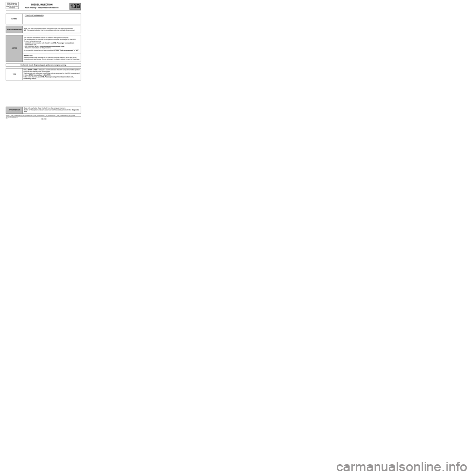
ET006CODE PROGRAMMED
STATUS DEFINITIONYES: This status indicates that the immobiliser code has been programmed.
NO: This status indicates that the immobiliser code has not been programmed.
NOTESThe injection immobiliser code is not written in the injection computer.
The programming of this code in the injection computer is managed by the UCH.
To carry out programming:
–establish communication with the UCH see 87B, Passenger compartment
connection unit.
–run command SC017 Program injection immobiliser code,
–follow the instructions for the procedure.
As long as this phase has not been completed, ET006 "Code programmed" is "NO".
IMPORTANT:
the immobiliser code is written in the injection computer memory at the end of the
computer auto-feed phase. Do not disconnect the battery before the end of this phase.
Conformity check: Engine stopped, ignition on or engine running.
YESStatus ET006 is YES if dialogue is possible between the UCH computer and the injection
computer and the key code is recognised.
The engine is only authorised to start if the code is recognised by the UCH computer and
if status ET003 Immobiliser is INACTIVE.
In the event of a fault, (see 87B, Passenger compartment connection unit,
conformity check).
DCM1.2_V48_ET006/DCM1.2_V4C_ET006/DCM1.2_V50_ET006/DCM1.2_V54_ET006/DCM1.2_V58_ET006/DCM1.2_V5C_ET006
Page 138 of 269
13B-138
AFTER REPAIRDeal with any faults. Clear the faults from the computer memory.
Switch off the ignition and carry out a road test followed by a test with the diagnostic
tool.
V10 MR-372-J84-13B100$150.mif
DIESEL INJECTION
Fault finding – Interpretation of statuses13B
DCM 1.2 Injection
Program No.: 4D
Vdiag No.: 48, 4C, 50,
54, 58, 5C
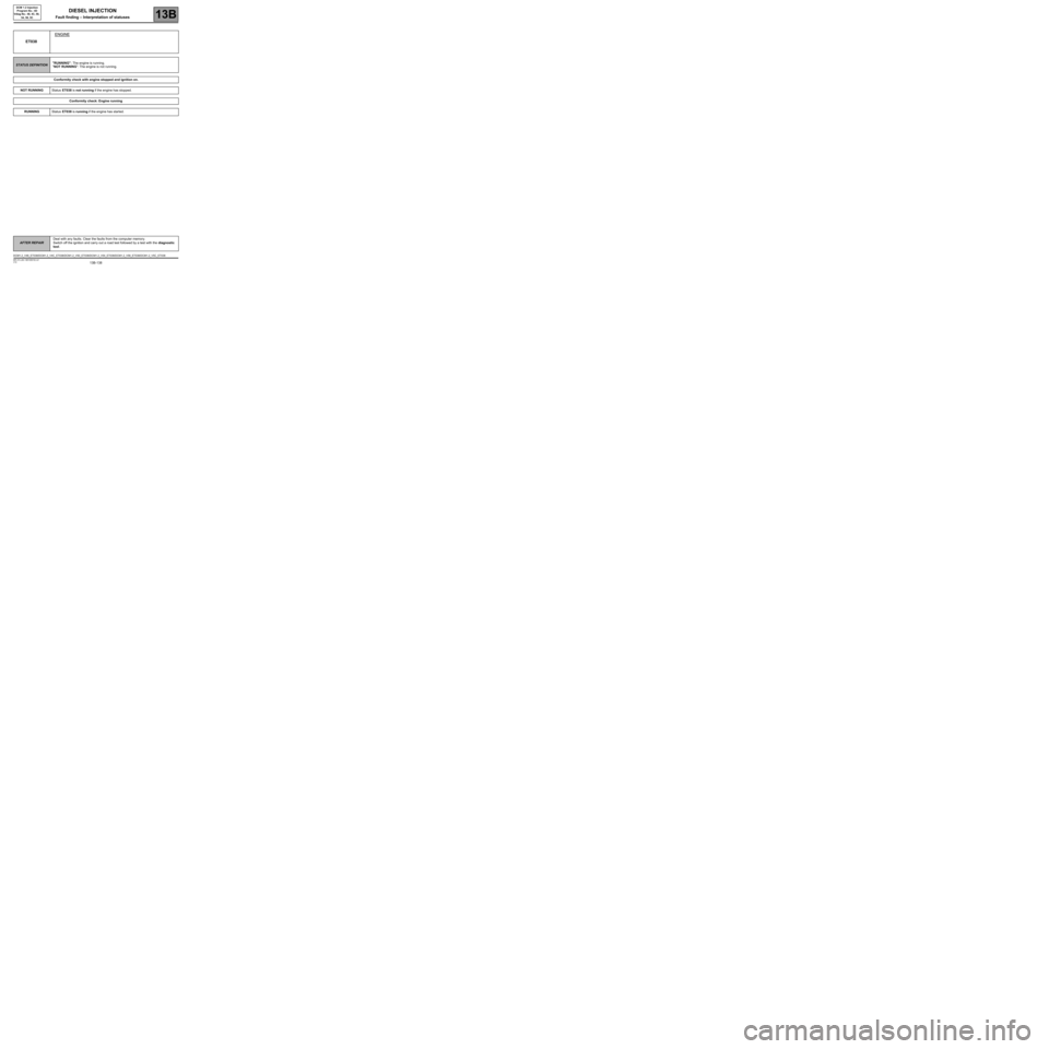
ET038ENGINE
STATUS DEFINITION"RUNNING": The engine is running.
"NOT RUNNING": The engine is not running.
Conformity check with engine stopped and ignition on.
NOT RUNNINGStatus ET038 is not running if the engine has stopped.
Conformity check: Engine running
RUNNINGStatus ET038 is running if the engine has started.
DCM1.2_V48_ET038/DCM1.2_V4C_ET038/DCM1.2_V50_ET038/DCM1.2_V54_ET038/DCM1.2_V58_ET038/DCM1.2_V5C_ET038