instrument panel RENAULT SCENIC 2010 J95 / 3.G Engine Compartment Connection Unit Workshop Manual
[x] Cancel search | Manufacturer: RENAULT, Model Year: 2010, Model line: SCENIC, Model: RENAULT SCENIC 2010 J95 / 3.GPages: 56
Page 2 of 56

87G - 2
ENGINE COMPARTMENT CONNECTION UNIT
Fault finding - Introduction
87G
V6 MR-372-J84-87G000$066_eng.mif
187G
UPC
Vdiag No.: 44ENGINE COMPARTMENT CONNECTION UNIT
Fault finding - Introduction
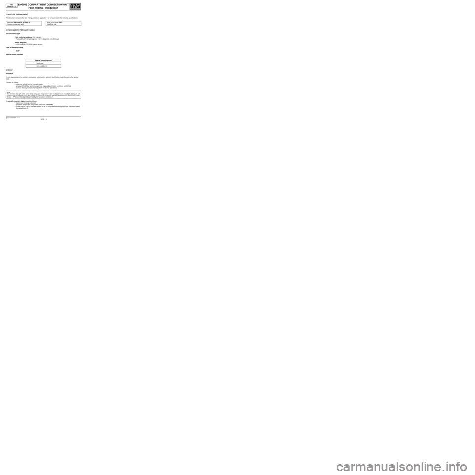
1. SCOPE OF THIS DOCUMENT
This document presents the fault finding procedure applicable to all computers with the following specifications:
2. PREREQUISITES FOR FAULT FINDING
Documentation type
Fault finding procedures (this manual):
–Assisted fault finding (integrated into the diagnostic tool), Dialogys.
Wiring diagrams:
–Visu-Schéma (CD-ROM), paper version.
Type of diagnostic tools
–CLIP
Special tooling required
3. RECAP
Procedure
To run diagnostics on the vehicle's computers, switch on the ignition in fault finding mode (forced + after ignition
feed).
Proceed as follows:
–insert the vehicle card in the card reader,
–press and hold Start button (longer than 5 seconds) with start conditions not fulfilled,
–connect the diagnostic tool and perform the desired operations.
To turn off the + APC feed proceed as follows:
–disconnect the diagnostic tool,
–press the Start button twice briefly (less than 3 seconds),
–check that the + APC has been turned off by the computer indicator lights on the instrument panel
being switched off. Vehicle(s): MEGANE II, SCENIC II
Function concerned: UPCName of computer: UPC
VDIAG No.: 44
Special tooling required
Multimeter
Universal bornier
Note:
The left-hand and right-hand xenon lamp computers are powered when the dipped beam headlights light up. It will
therefore not be possible to run fault finding on them until the ignition has been switched on in fault finding mode
(forced + APC) and the dipped beam headlights have been switched on.
MR-372-J84-87G000$066_eng.mif
Page 27 of 56

87G - 27
ENGINE COMPARTMENT CONNECTION UNIT
Fault finding - Interpretation of statuses
87G
V6 MR-372-J84-87G000$660_eng.mif
UPC
Vdiag No.: 44ENGINE COMPARTMENT CONNECTION UNIT
Fault finding - Interpretation of statuses
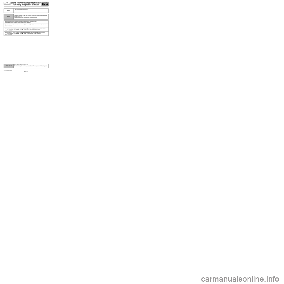
ET001
BATTERY WARNING LIGHT
NOTESCheck that the status is OUT with the engine running and LIT with the engine stopped
and the ignition on.
Check consistency with the instrument panel warning light.
With the engine running, check that the battery voltage is much higher than +12 V.
Perform a fault finding procedure on the charge circuit if necessary.
Check the status and the connection of connector PEM on the UPC and of the connections on the alternator.
Repair if necessary.
Turn off the ignition and ensure that there is insulation against +12 V and continuity in the connection:
UPC connector PEM track 8 Track 1 of the alternator 2-track connector
Repair if necessary.
With the ignition on, ensure that there is insulation against earth and the continuity in the connection:
UPC connector PEM track 8 Track 1 of the alternator 2-track connector
Repair if necessary.
AFTER REPAIRDeal with any other possible faults.
Switch off the ignition and carry out a road test followed by a test with the diagnostic
tool.
MR-372-J84-87G000$660_eng.mif
Page 56 of 56

87G - 56
ENGINE COMPARTMENT CONNECTION UNIT
Fault finding - Fault Finding Chart (ALP)
87G
V6 MR-372-J84-87G000$924_eng.mif
UPC
Vdiag No.: 44
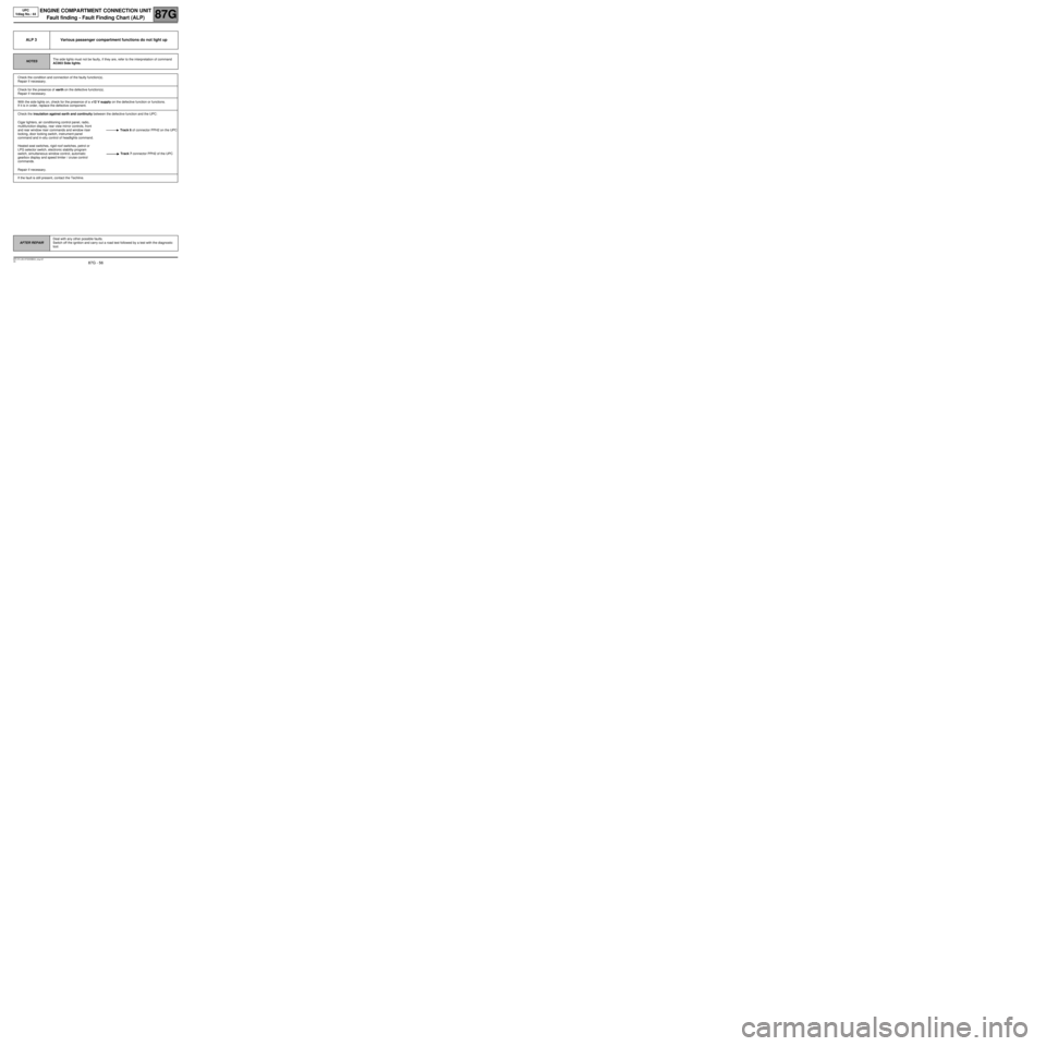
ALP 3 Various passenger compartment functions do not light up
NOTESThe side lights must not be faulty, if they are, refer to the interpretation of command
AC003 Side lights.
Check the condition and connection of the faulty function(s).
Repair if necessary.
Check for the presence of earth on the defective function(s).
Repair if necessary.
With the side lights on, check for the presence of a +12 V supply on the defective function or functions.
If it is in order, replace the defective component.
Check the insulation against earth and continuity between the defective function and the UPC:
Cigar lighters, air conditioning control panel, radio,
multifunction display, rear view mirror controls, front
and rear window riser commands and window riser
locking, door locking switch, instrument panel
command and in-situ control of headlights command.Track 6 of connector PPH2 on the UPC
Heated seat switches, rigid roof switches, petrol or
LPG selector switch, electronic stability program
switch, simultaneous window control, automatic
gearbox display and speed limiter / cruise control
commands.Track 7 connector PPH2 of the UPC
Repair if necessary.
If the fault is still present, contact the Techline.
AFTER REPAIRDeal with any other possible faults.
Switch off the ignition and carry out a road test followed by a test with the diagnostic
tool.