sensor RENAULT SCENIC 2010 J95 / 3.G Petrol Injection S3000 Injection Workshop Manual
[x] Cancel search | Manufacturer: RENAULT, Model Year: 2010, Model line: SCENIC, Model: RENAULT SCENIC 2010 J95 / 3.GPages: 230, PDF Size: 0.92 MB
Page 205 of 230
PETROL INJECTION
Fault finding - Interpretation of parameters
17B
17B - 205
PETROL INJECTION
Fault finding - Interpretation of parameters
17B
17B - 205V9 MR-372-J84-17B050$705.mif
S3000 Injection
Program No.: AD
Vdiag No.: 4C / 54
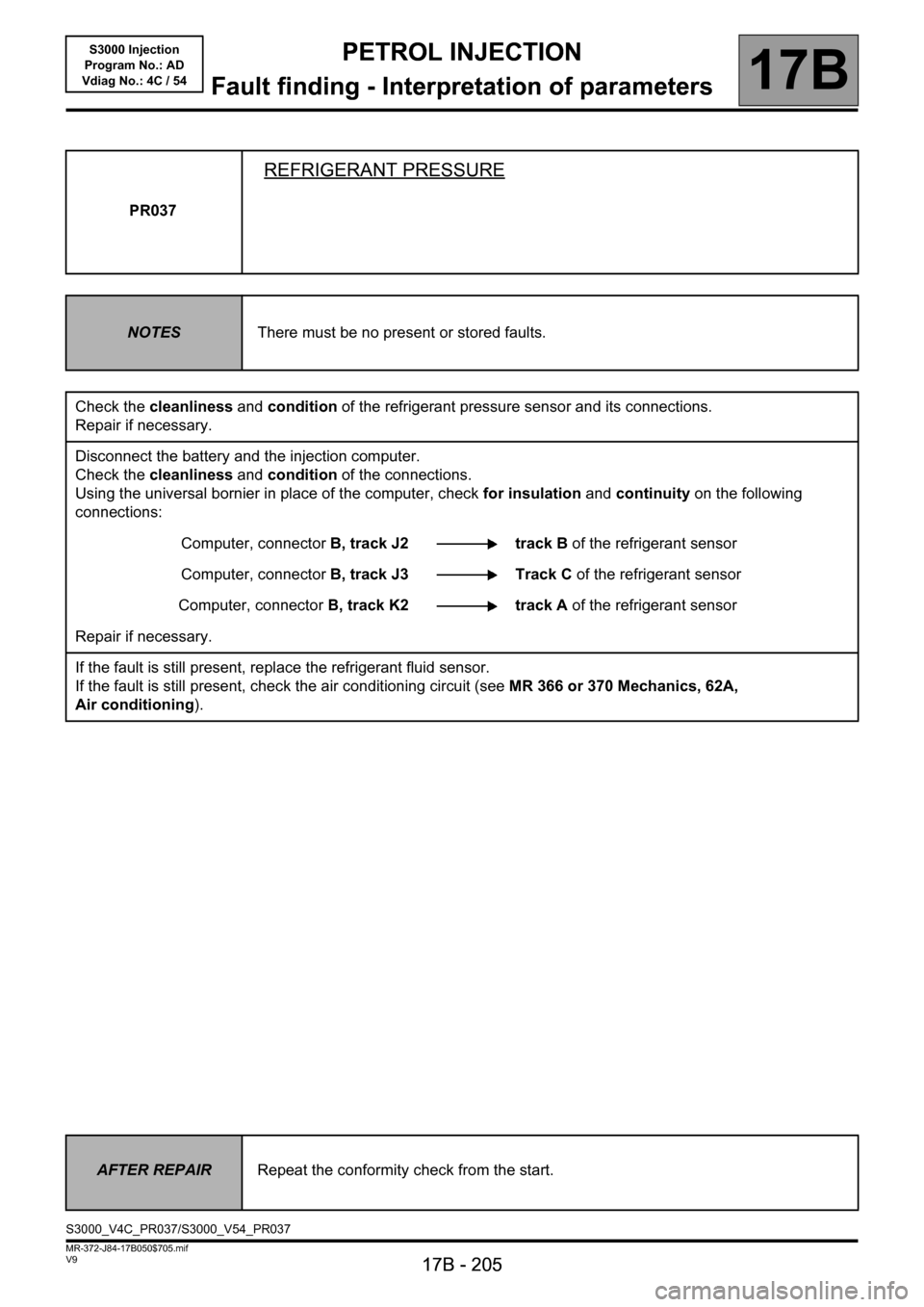
PR037
REFRIGERANT PRESSURE
NOTESThere must be no present or stored faults.
Check the cleanliness and condition of the refrigerant pressure sensor and its connections.
Repair if necessary.
Disconnect the battery and the injection computer.
Check the cleanliness and condition of the connections.
Using the universal bornier in place of the computer, check for insulation and continuity on the following
connections:
Computer, connectorB, track J2 track B of the refrigerant sensor
Computer, connectorB, track J3 Track C of the refrigerant sensor
Computer, connectorB, track K2 track A of the refrigerant sensor
Repair if necessary.
If the fault is still present, replace the refrigerant fluid sensor.
If the fault is still present, check the air conditioning circuit (see MR 366 or 370 Mechanics, 62A,
Air conditioning).
AFTER REPAIRRepeat the conformity check from the start.
S3000_V4C_PR037/S3000_V54_PR037
Page 207 of 230
PETROL INJECTION
Fault finding - Interpretation of parameters
17B
17B - 207
PETROL INJECTION
Fault finding - Interpretation of parameters
17B
17B - 207V9 MR-372-J84-17B050$705.mif
S3000 Injection
Program No.: AD
Vdiag No.: 4C / 54
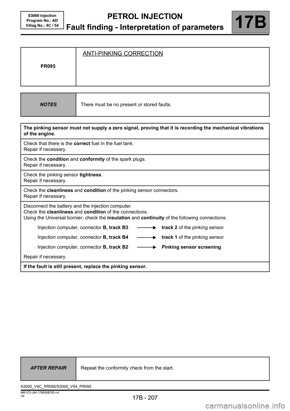
PR095
ANTI-PINKING CORRECTION
NOTESThere must be no present or stored faults.
The pinking sensor must not supply a zero signal, proving that it is recording the mechanical vibrations
of the engine.
Check that there is the correct fuel in the fuel tank.
Repair if necessary.
Check the condition and conformity of the spark plugs.
Repair if necessary.
Check the pinking sensor tightness.
Repair if necessary.
Check the cleanliness and condition of the pinking sensor connectors.
Repair if necessary.
Disconnect the battery and the injection computer.
Check the cleanliness and condition of the connections.
Using the Universal bornier, check the insulation and continuity of the following connections:
Injection computer, connectorB, track B3 track 2 of the pinking sensor
Injection computer, connectorB, track B4 track 1 of the pinking sensor
Injection computer, connectorB, track B2 Pinking sensor screening
Repair if necessary.
If the fault is still present, replace the pinking sensor.
AFTER REPAIRRepeat the conformity check from the start.
S3000_V4C_PR095/S3000_V54_PR095
Page 208 of 230
PETROL INJECTION
Fault finding - Interpretation of parameters
17B
17B - 208
PETROL INJECTION
Fault finding - Interpretation of parameters
17B
17B - 208V9 MR-372-J84-17B050$705.mif
S3000 Injection
Program No.: AD
Vdiag No.: 4C / 54
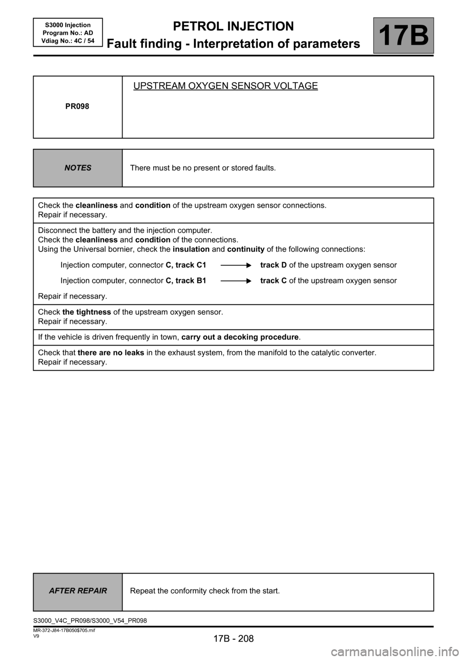
PR098
UPSTREAM OXYGEN SENSOR VOLTAGE
NOTESThere must be no present or stored faults.
Check the cleanliness and condition of the upstream oxygen sensor connections.
Repair if necessary.
Disconnect the battery and the injection computer.
Check the cleanliness and condition of the connections.
Using the Universal bornier, check the insulation and continuity of the following connections:
Injection computer, connectorC, track C1 track D of the upstream oxygen sensor
Injection computer, connectorC, track B1 track C of the upstream oxygen sensor
Repair if necessary.
Check the tightness of the upstream oxygen sensor.
Repair if necessary.
If the vehicle is driven frequently in town, carry out a decoking procedure.
Check that there are no leaks in the exhaust system, from the manifold to the catalytic converter.
Repair if necessary.
AFTER REPAIRRepeat the conformity check from the start.
S3000_V4C_PR098/S3000_V54_PR098
Page 209 of 230

PETROL INJECTION
Fault finding - Interpretation of parameters
17B
17B - 209
PETROL INJECTION
Fault finding - Interpretation of parameters
17B
17B - 209V9 MR-372-J84-17B050$705.mif
S3000 Injection
Program No.: AD
Vdiag No.: 4C / 54
PR098
CONTINUED
If the fault is still present, replace the upstream oxygen sensor.
If the fault has still not been cured, continue with the checks.
Check:
– the condition of the air filter,
– that the air inlet circuit is not blocked,
– the condition and conformity of the spark plugs,
– that the catalytic converter is not clogged,
– the sealing between the throttle valve and inlet manifold,
– the manifold pressure sensor sealing,
– the fuel vapour absorber bleed, which must not be jammed open,'
– the fuel vapour absorber bleed system sealing,
– the brake servo system sealing,
– the cylinder head oil vapour recovery system sealing,
– the sealing between the inlet manifold and cylinder head,
– the exhaust pipe sealing between the cylinder head and catalytic converter.
– the fuel flow rate and pressure.
If the idle speed is not stable, check:
– the timing adjustment,
– the hydraulic tappets if there is camshaft noise (see MR 364 or 370 Mechanics, 11A, Top and front of engine),
– the cylinder compressions.
Drive the vehicle to check the repair.
AFTER REPAIRRepeat the conformity check from the start.
Page 210 of 230
PETROL INJECTION
Fault finding - Interpretation of parameters
17B
17B - 210
PETROL INJECTION
Fault finding - Interpretation of parameters
17B
17B - 210V9 MR-372-J84-17B050$705.mif
S3000 Injection
Program No.: AD
Vdiag No.: 4C / 54
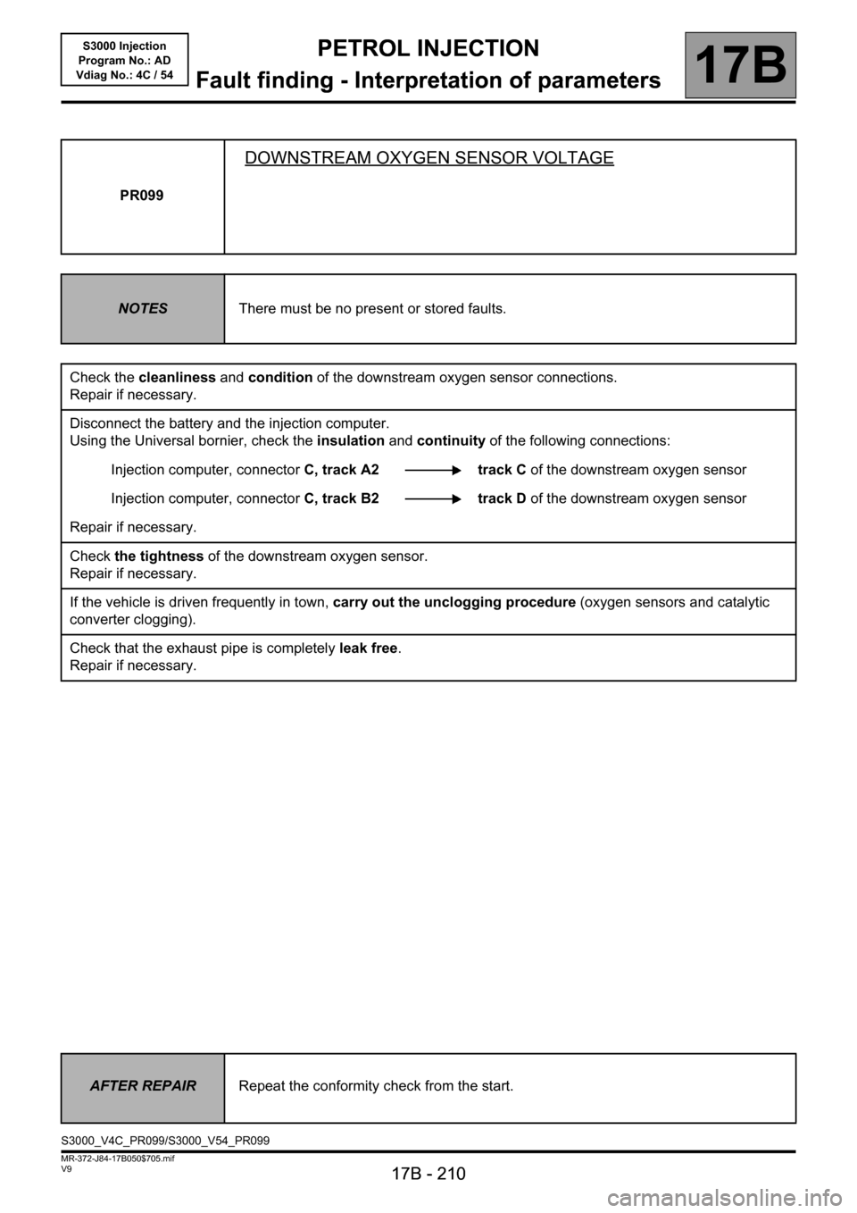
PR099
DOWNSTREAM OXYGEN SENSOR VOLTAGE
NOTESThere must be no present or stored faults.
Check the cleanliness and condition of the downstream oxygen sensor connections.
Repair if necessary.
Disconnect the battery and the injection computer.
Using the Universal bornier, check the insulation and continuity of the following connections:
Injection computer, connectorC, track A2 track C of the downstream oxygen sensor
Injection computer, connectorC, track B2 track D of the downstream oxygen sensor
Repair if necessary.
Check the tightness of the downstream oxygen sensor.
Repair if necessary.
If the vehicle is driven frequently in town, carry out the unclogging procedure (oxygen sensors and catalytic
converter clogging).
Check that the exhaust pipe is completely leak free.
Repair if necessary.
AFTER REPAIRRepeat the conformity check from the start.
S3000_V4C_PR099/S3000_V54_PR099
Page 211 of 230

PETROL INJECTION
Fault finding - Interpretation of parameters
17B
17B - 211
PETROL INJECTION
Fault finding - Interpretation of parameters
17B
17B - 211V9 MR-372-J84-17B050$705.mif
S3000 Injection
Program No.: AD
Vdiag No.: 4C / 54
PR099
CONTINUED
Replace the downstream oxygen sensor.
If the fault is still present, the catalytic converter is certainly damaged.
If the catalytic converter is defective, determine the cause of the destruction, otherwise the new catalytic
converter may be damaged in turn.
Remove the catalytic converter.
Various things may destroy a catalytic converter:
–deformation (impact),
–thermal shock (cold water splashed onto a hot catalytic converter can damage it),
–defective injector or ignition: the catalytic converter is damaged by contact with fuel (coil fault, coil control fault,
injector jammed open),
–injector leak,
–abnormal oil or coolant consumption (defective cylinder head gasket),
–use of a fuel additive or other equivalent product (obtain information from the customer because this type of
product can contaminate the catalytic converter and render it useless sooner or later).
Look up the service history of the vehicle or, if this is not possible, ask the customer if the vehicle has had injection
or ignition faults.
If the cause of the catalytic converter damage has been found and the fault has disappeared, replace the
catalytic converter.
AFTER REPAIRRepeat the conformity check from the start.
Page 212 of 230
PETROL INJECTION
Fault finding - Interpretation of parameters
17B
17B - 212
PETROL INJECTION
Fault finding - Interpretation of parameters
17B
17B - 212V9 MR-372-J84-17B050$705.mif
S3000 Injection
Program No.: AD
Vdiag No.: 4C / 54
PR312
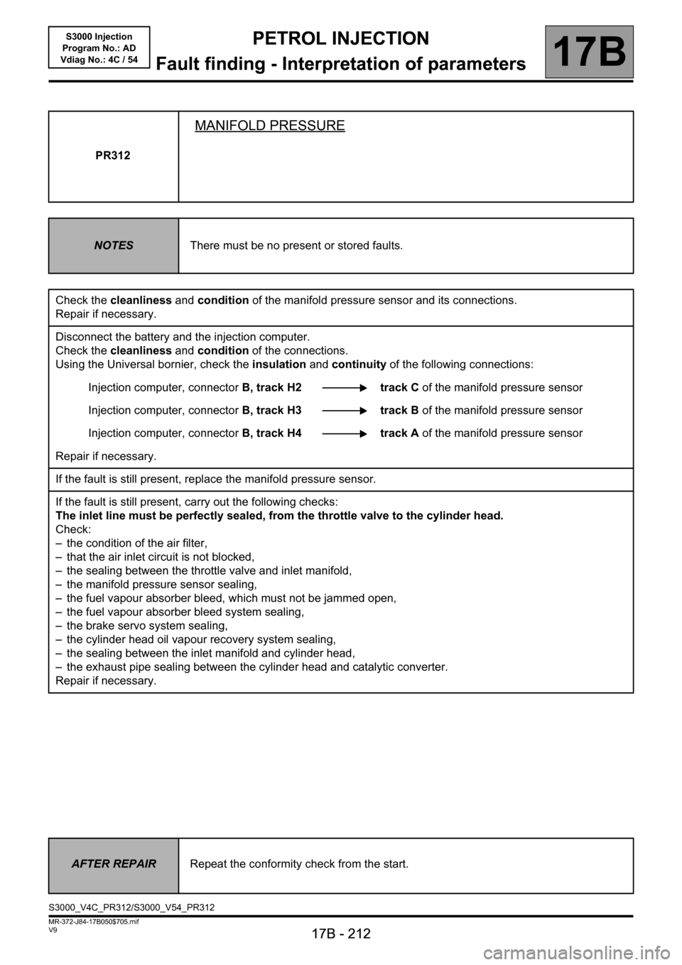
MANIFOLD PRESSURE
NOTESThere must be no present or stored faults.
Check the cleanliness and condition of the manifold pressure sensor and its connections.
Repair if necessary.
Disconnect the battery and the injection computer.
Check the cleanliness and condition of the connections.
Using the Universal bornier, check the insulation and continuity of the following connections:
Injection computer, connectorB, track H2 track C of the manifold pressure sensor
Injection computer, connectorB, track H3 track B of the manifold pressure sensor
Injection computer, connectorB, track H4 track A of the manifold pressure sensor
Repair if necessary.
If the fault is still present, replace the manifold pressure sensor.
If the fault is still present, carry out the following checks:
The inlet line must be perfectly sealed, from the throttle valve to the cylinder head.
Check:
– the condition of the air filter,
– that the air inlet circuit is not blocked,
– the sealing between the throttle valve and inlet manifold,
– the manifold pressure sensor sealing,
– the fuel vapour absorber bleed, which must not be jammed open,
– the fuel vapour absorber bleed system sealing,
– the brake servo system sealing,
– the cylinder head oil vapour recovery system sealing,
– the sealing between the inlet manifold and cylinder head,
– the exhaust pipe sealing between the cylinder head and catalytic converter.
Repair if necessary.
AFTER REPAIRRepeat the conformity check from the start.
S3000_V4C_PR312/S3000_V54_PR312
Page 213 of 230

PETROL INJECTION
17B
17B-213
PETROL INJECTION
17B
17B-213V9 MR-372-J84-17B050$752.mif
S3000 Injection
Program No.: AD
Vdiag No.: 4C / 54PETROL INJECTION
Fault finding - Command summary table
Tool command Diagnostic tool title
RZ001Fault memory
RZ005Programming
AC017Canister bleed solenoid valve
AC018Upstream O
2 sensor heating
AC019Downstream O
2 sensor heating
AC027Motorised throttle
AC079Actuator static test
AC195Electric coolant pump
AC253Camshaft dephaser: Normal control
AC254Camshaft dephaser: ON/OFF control
VP020Enter VIN
MR-372-J84-17B050$752.mif
Page 216 of 230
PETROL INJECTION
Fault finding - Interpretation of commands
17B
17B - 216
PETROL INJECTION
Fault finding - Interpretation of commands
17B
17B - 216V9 MR-372-J84-17B050$799.mif
S3000 Injection
Program No.: AD
Vdiag No.: 4C / 54
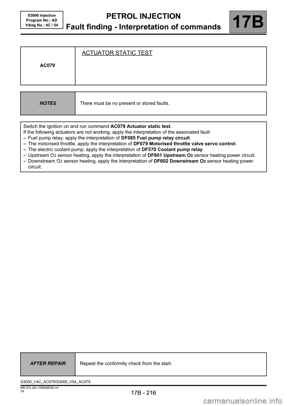
AC079
ACTUATOR STATIC TEST
NOTESThere must be no present or stored faults.
Switch the ignition on and run command AC079 Actuator static test.
If the following actuators are not working, apply the interpretation of the associated fault:
– Fuel pump relay, apply the interpretation of DF085 Fuel pump relay circuit.
– The motorised throttle, apply the interpretation of DF079 Motorised throttle valve servo control.
– The electric coolant pump, apply the interpretation of DF570 Coolant pump relay.
–Upstream O
2 sensor heating, apply the interpretation of DF601 Upstream O2 sensor heating power circuit.
– Downstream O
2 sensor heating, apply the interpretation of DF602 Downstream O2 sensor heating power
circuit.
AFTER REPAIRRepeat the conformity check from the start.
S3000_V4C_AC079/S3000_V54_AC079
Page 219 of 230
PETROL INJECTION
Fault finding - Test
17B
PETROL INJECTION
Fault finding - Test
17B
17B-219V9 MR-372-J84-17B050$846.mif
S3000 Injection
Program No.: AD
Vdiag No.: 4C / 54
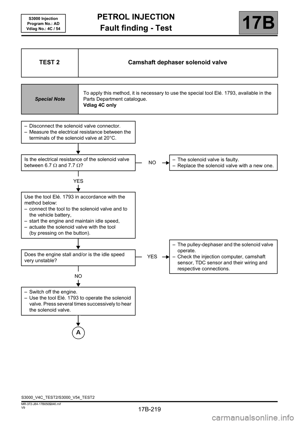
TEST 2 Camshaft dephaser solenoid valve
Special NoteTo apply this method, it is necessary to use the special tool Elé. 1793, available in the
Parts Department catalogue.
Vdiag 4C only
– Disconnect the solenoid valve connector.
– Measure the electrical resistance between the
terminals of the solenoid valve at 20°C.
Is the electrical resistance of the solenoid valve
between 6.7Ω and 7.7Ω?
YES
Use the tool Elé. 1793 in accordance with the
method below:
– connect the tool to the solenoid valve and to
the vehicle battery,
– start the engine and maintain idle speed,
– actuate the solenoid valve with the tool
(by pressing on the button).
Does the engine stall and/or is the idle speed
very unstable?
NO
– Switch off the engine.
– Use the tool Elé. 1793 to operate the solenoid
valve. Press several times successively to hear
the solenoid valve.
NO– The solenoid valve is faulty.
– Replace the solenoid valve with a new one.
YES– The pulley-dephaser and the solenoid valve
operate.
– Check the injection computer, camshaft
sensor, TDC sensor and their wiring and
respective connections.
S3000_V4C_TEST2/S3000_V54_TEST2