DF095 RENAULT SCENIC 2010 J95 / 3.G Petrol Injection S3000 Injection Workshop Manual
[x] Cancel search | Manufacturer: RENAULT, Model Year: 2010, Model line: SCENIC, Model: RENAULT SCENIC 2010 J95 / 3.GPages: 230, PDF Size: 0.92 MB
Page 18 of 230

PETROL INJECTION
Fault finding - System operation
17B
17B - 18
PETROL INJECTION
Fault finding - System operation
17B
17B - 18V9 MR-372-J84-17B050$094.mif
S3000 Injection
Program No.: AD
Vdiag No.: 4C / 54
Table of defect modes:
Type 1 Type 2 Type 3 Type 4 Type 5 Type 6
DF004 Turbocharging pressure
sensor circuit---2.DEF1.DEF
2.DEF1.DEF
2.DEF
DF011 Sensor feed voltage no. 11.DEF 1.DEF - 1.DEF - -
DF012 Sensor feed voltage no. 2---1.DEF1.DEF-
DF038 Computer1.DEF 1.DEF - - 1.DEF -
DF046 Battery voltage1.DEF 1.DEF - - - -
DF054 Turbocharging solenoid valve
control circuit-----CO/CC.0./
CC.1
DF078 Motorised throttle control
circuit1.DEF 1.DEF - - - -
DF079 Motorised throttle valve
automatic control6.DEF/CO 6.DEF/CO -2.DEF
3.DEF
4.DEF--
DF089 Inlet manifold pressure sensor
circuit----1.DEF
2.DEF-
DF095 Throttle potentiometer circuit
gang 1CO.0/
CC.1CO.0/
CC.1-CO.0/
CC.1--
DF096 Throttle potentiometer circuit
gang 2CO.0/
CC.1CO.0/
CC.1-CO.0/
CC.1--
DF196 Pedal potentiometer circuit
gang 1--1.DEFCO/CC.0./
CC.1
1.DEF--
DF198 Pedal potentiometer circuit
gang 2--CO/CC.0./
CC.1CO/CC.0./
CC.1--
DF650 Accelerator pedal position
signal--1.DEF1.DEF--
Page 31 of 230

PETROL INJECTION
Fault finding - Fault summary table
17B
17B-31
PETROL INJECTION
Fault finding - Fault summary table
17B
17B-31V9 MR-372-J84-17B050$282.mif
S3000 Injection
Program No.: AD
Vdiag No.: 4C / 54
Tool faultAssociated
DTC codeDescriptionLevel 2 fault
warning light
(Red brake
warning light)Level 1 fault
warning light
(Orange
injection
warning light)No warning
light onOBD
warning light
DF079 0638Motorised throttle
valve automatic
control2.DEF/
3.DEF/
4.DEF/CO/
6.DEF1.DEF/5.DEF/
7.DEF/8.DEF
DF080 0010Camshaft
dephaser circuitCO/CC.0/
CC.1/1.DEF/
2.DEF/3.DEF/
4.DEF/5.DEF
DF081 0443Canister bleed
solenoid valve
circuitCC.O/1.DEF CO/ CC.1
DF084 0685Actuator relay
control circuitCO/CC.0
CC.1
DF085 0627Fuel pump relay
control circuitCO/CC.0
CC.1/1.DEF
DF088 0325Pinking sensor
circuit1.DEF/2.DEF
DF089 0105Inlet manifold
pressure sensor
circuit1.DEF
2.DEF
3.DEF1.DEF
2.DEF
3.DEF
DF091 0500Vehicle speed
signal1.DEF/2.DEF
DF092 0130Upstream oxygen
sensor circuitCO.0
CC.1/1.DEF
2.DEF
DF093 0136Downstream
oxygen sensor
circuitCO.0
CC.1/1.DEF
DF095 0120Throttle
potentiometer
circuit gang 1CO.0/CC.1
1.DEF/2.DEF
DF096 0220Throttle
potentiometer
circuit track 2CO.0/ CC.1
DF099 C101Automatic gearbox
or sequential
gearbox
connection via the
multiplex network1.DEF/2.DEF/
3.DEF/4.DEF
DF101 C122ESP multiplex
connection1.DEF
Page 59 of 230

PETROL INJECTION
Fault finding - Interpretation of faults
17B
17B-59
PETROL INJECTION
Fault finding - Interpretation of faults
17B
17B-59V9 MR-372-J84-17B050$329.mif
S3000 Injection
Program No.: AD
Vdiag No.: 4C / 54
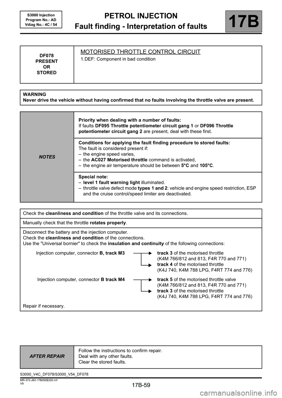
DF078
PRESENT
OR
STOREDMOTORISED THROTTLE CONTROL CIRCUIT
1.DEF: Component in bad condition
WARNING
Never drive the vehicle without having confirmed that no faults involving the throttle valve are present.
NOTESPriority when dealing with a number of faults:
If faults DF095 Throttle potentiometer circuit gang 1 or DF096 Throttle
potentiometer circuit gang 2 are present, deal with these first.
Conditions for applying the fault finding procedure to stored faults:
The fault is considered present if:
– the engine speed varies,
–the AC027 Motorised throttle command is activated,
– the engine air temperature should be between 5°C and 105°C.
Special note:
–level 1 fault warning light illuminated.
– throttle valve defect mode types 1 and 2: vehicle and engine speed restriction, ESP
and the cruise control/speed limiter are deactivated.
Check the cleanliness and condition of the throttle valve and its connections.
Manually check that the throttle rotates properly.
Disconnect the battery and the injection computer.
Check the cleanliness and condition of the connections.
Use the "Universal bornier" to check the insulation and continuity of the following connections:
Injection computer, connectorB, track M3 track 3 of the motorised throttle
(K4M 766/812 and 813, F4R 770 and 771)
track 4of the motorised throttle
(K4J 740, K4M 788 LPG, F4RT 774 and 776)
Injection computer, connectorB track M4 track 5 of the motorised throttle valve
(K4M 766/812 and 813, F4R 770 and 771)
track 3 of the motorised throttle
(K4J 740, K4M 788 LPG, F4RT 774 and 776)
Repair if necessary.
AFTER REPAIRFollow the instructions to confirm repair.
Deal with any other faults.
Clear the stored faults.
S3000_V4C_DF078/S3000_V54_DF078
Page 61 of 230

PETROL INJECTION
Fault finding - Interpretation of faults
17B
17B-61
PETROL INJECTION
Fault finding - Interpretation of faults
17B
17B-61V9 MR-372-J84-17B050$329.mif
S3000 Injection
Program No.: AD
Vdiag No.: 4C / 54
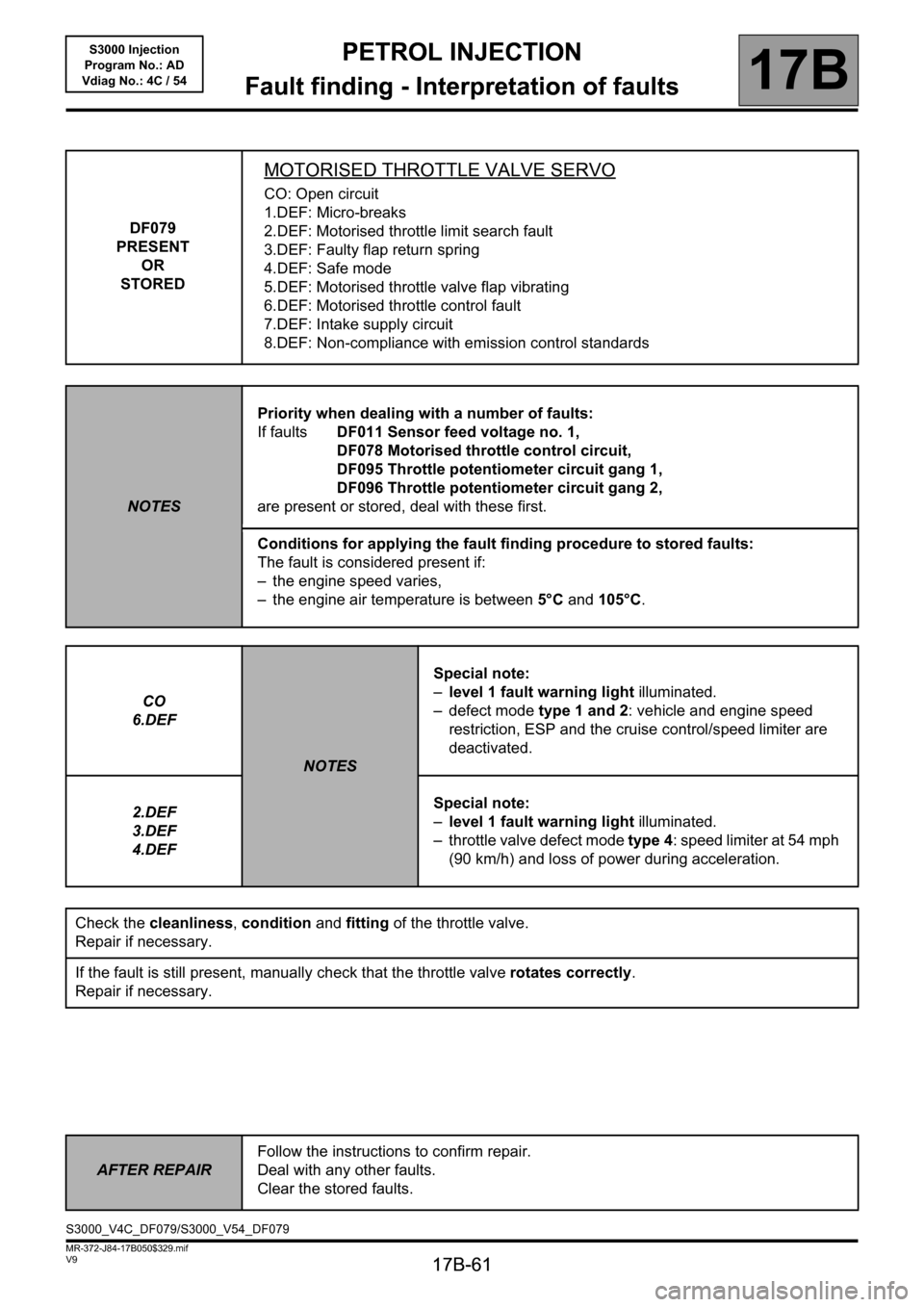
DF079
PRESENT
OR
STORED
MOTORISED THROTTLE VALVE SERVO
CO: Open circuit
1.DEF: Micro-breaks
2.DEF: Motorised throttle limit search fault
3.DEF: Faulty flap return spring
4.DEF: Safe mode
5.DEF: Motorised throttle valve flap vibrating
6.DEF: Motorised throttle control fault
7.DEF: Intake supply circuit
8.DEF: Non-compliance with emission control standards
NOTESPriority when dealing with a number of faults:
If faultsDF011 Sensor feed voltage no. 1,
DF078 Motorised throttle control circuit,
DF095 Throttle potentiometer circuit gang 1,
DF096 Throttle potentiometer circuit gang 2,
are present or stored, deal with these first.
Conditions for applying the fault finding procedure to stored faults:
The fault is considered present if:
– the engine speed varies,
– the engine air temperature is between 5°C and 105°C.
CO
6.DEF
NOTESSpecial note:
–level 1 fault warning light illuminated.
– defect mode type 1 and 2: vehicle and engine speed
restriction, ESP and the cruise control/speed limiter are
deactivated.
2.DEF
3.DEF
4.DEFSpecial note:
–level 1 fault warning light illuminated.
– throttle valve defect mode type 4: speed limiter at 54 mph
(90 km/h) and loss of power during acceleration.
Check the cleanliness, condition and fitting of the throttle valve.
Repair if necessary.
If the fault is still present, manually check that the throttle valve rotates correctly.
Repair if necessary.
AFTER REPAIRFollow the instructions to confirm repair.
Deal with any other faults.
Clear the stored faults.
S3000_V4C_DF079/S3000_V54_DF079
Page 75 of 230

PETROL INJECTION
Fault finding - Interpretation of faults
17B
17B-75
PETROL INJECTION
Fault finding - Interpretation of faults
17B
17B-75V9 MR-372-J84-17B050$376.mif
S3000 Injection
Program No.: AD
Vdiag No.: 4C / 54
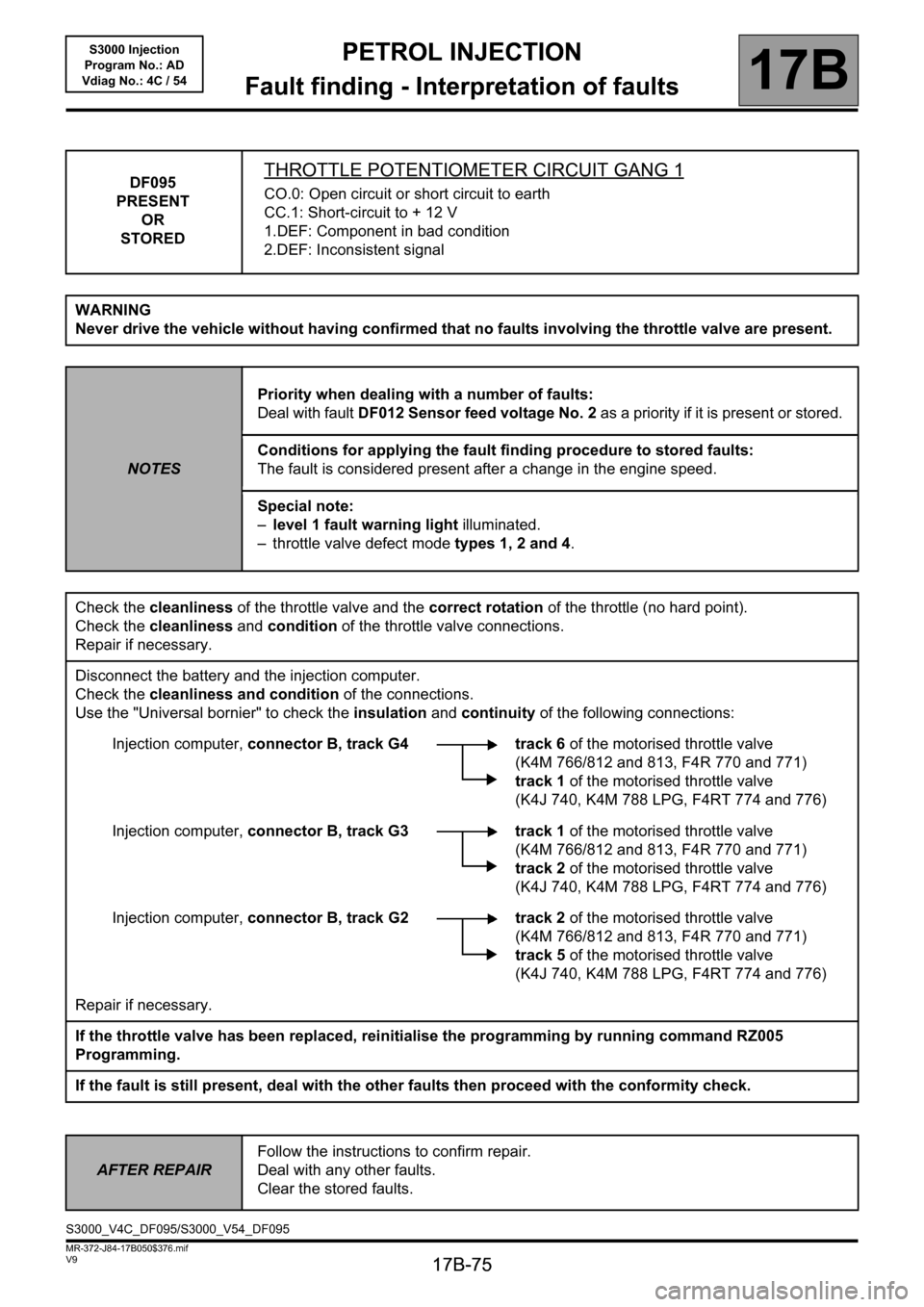
DF095
PRESENT
OR
STOREDTHROTTLE POTENTIOMETER CIRCUIT GANG 1
CO.0: Open circuit or short circuit to earth
CC.1: Short-circuit to + 12 V
1.DEF: Component in bad condition
2.DEF: Inconsistent signal
WARNING
Never drive the vehicle without having confirmed that no faults involving the throttle valve are present.
NOTESPriority when dealing with a number of faults:
Deal with fault DF012 Sensor feed voltage No. 2 as a priority if it is present or stored.
Conditions for applying the fault finding procedure to stored faults:
The fault is considered present after a change in the engine speed.
Special note:
–level 1 fault warning light illuminated.
– throttle valve defect mode types 1, 2 and 4.
Check the cleanliness of the throttle valve and the correct rotation of the throttle (no hard point).
Check the cleanliness and condition of the throttle valve connections.
Repair if necessary.
Disconnect the battery and the injection computer.
Check the cleanliness and condition of the connections.
Use the "Universal bornier" to check the insulation and continuity of the following connections:
Injection computer, connector B, track G4 track 6 of the motorised throttle valve
(K4M 766/812 and 813, F4R 770 and 771)
track 1 of the motorised throttle valve
(K4J 740, K4M 788 LPG, F4RT 774 and 776)
Injection computer, connector B, track G3 track 1 of the motorised throttle valve
(K4M 766/812 and 813, F4R 770 and 771)
track 2 of the motorised throttle valve
(K4J 740, K4M 788 LPG, F4RT 774 and 776)
Injection computer, connector B, track G2 track 2 of the motorised throttle valve
(K4M 766/812 and 813, F4R 770 and 771)
track 5 of the motorised throttle valve
(K4J 740, K4M 788 LPG, F4RT 774 and 776)
Repair if necessary.
If the throttle valve has been replaced, reinitialise the programming by running command RZ005
Programming.
If the fault is still present, deal with the other faults then proceed with the conformity check.
AFTER REPAIRFollow the instructions to confirm repair.
Deal with any other faults.
Clear the stored faults.
S3000_V4C_DF095/S3000_V54_DF095
Page 122 of 230

PETROL INJECTION
Fault finding - Conformity check
17B
17B-122
PETROL INJECTION
Fault finding - Conformity check
17B
17B-122V9 MR-372-J84-17B050$470.mif
S3000 Injection
Program No.: AD
Vdiag No.: 4C / 54
SUB FUNCTION: (TURBO/INLET) (continued):
OCR: Opening Cycle Ratio
NOTESOnly check the conformity after a complete check with the diagnostic tool. The values
shown in this conformity check are given as a guide.
Application conditions: Engine off, ignition on.
Order FunctionParameter or Status
Checked or ActionDisplay and notes Fault finding
8 Air flow PR018:Estimated air
flowIndicates the air flow
value estimated by the
motorised throttle
valve.
PR018= 0kg/hIf there is a fault, apply the
interpretation of faults
DF095 Throttle
potentiometer circuit
gang 1 and DF096
Throttle potentiometer
circuit gang 2.
9
Camshaft
dephaser (Only
on K4M
engines)ET083:Camshaft
dephaser in
defect modeSTATUS 1: This defect
mode covers all faults
that affect the dephaser
position measurement.
The dephaser is set to the
lower stop and the
camshaft angle
measurement is forced
to 0. Tooth signal fault.
STATUS 2: This defect
mode covers all faults
that affect the dephaser
(pulley and solenoid
valve). The dephaser is
set to the low stop.
NOFor STATUS 1, carry out
a camshaft signal/tooth
consistency diagnostic.
For STATUS 2, carry out
fault finding on the
camshaft dephaser
position.
10 PR094:Camshaft
dephaser OCR
setpointShows required camshaft
offset value (in %).
PR094 = 0%
WITHOUT
11 ET086:Camshaft
dephaser
controlACTIVE
INACTIVE
12electric coolant
pumpAC195:Electric coolant
pumpThe pump should be
heard operatingIn the event of a fault,
apply interpretation of
DF570 Coolant pump
relay.
Page 129 of 230

PETROL INJECTION
Fault finding - Conformity check
17B
17B-129
PETROL INJECTION
Fault finding - Conformity check
17B
17B-129V9 MR-372-J84-17B050$470.mif
S3000 Injection
Program No.: AD
Vdiag No.: 4C / 54
DRIVER PARAMETERS SUB-FUNCTION:
NOTESOnly check the conformity after a complete check with the diagnostic tool. The values
shown in this conformity check are given as a guide.
Application conditions: Engine off, ignition on.
Order FunctionParameter or Status Checked
or ActionDisplay and notes Fault finding
1
Motorised
throttleET051:Throttle stop
programmingCOMPLETED
Run command
RZ005
Programming. If the
parameters or
statuses are still not
correct, contact the
Techline. 2ET082:Motorised throttle
positionNo load
Full load
INTERMEDIATE
3 PR116:Motorised throttle
corrected position
setpointPR116 ≈ 2%
4 PR111:Motorised throttle
position corrected
valueNo load < 15 %
Full load >30%
5 PR097:Motorised throttle
lower stop
programmed value.5.96% < PR097
< 13.96%
6 PR096:Motorised throttle
upper stop
programmed value80%
position5% < PR429 < 25%
8 PR118:Measured throttle
position gang 1No load = 4 %
Full load = 99 %
Default value: 0%If there is a fault, use
the interpretation for
DF095 Throttle
potentiometer
circuit gang 1.
9 PR119:Measured throttle
position gang 2No load = 4 %
Full load = 100 %
Default value: 100%If there is a fault, use
the interpretation for
DF096 Throttle
potentiometer
circuit gang 2.
Page 132 of 230

PETROL INJECTION
Fault finding - Conformity check
17B
17B-132
PETROL INJECTION
Fault finding - Conformity check
17B
17B-132V9 MR-372-J84-17B050$470.mif
S3000 Injection
Program No.: AD
Vdiag No.: 4C / 54
SUB-FUNCTION: DRIVER PARAMETERS (CONTINUED 3):
NOTESOnly check the conformity after a complete check with the diagnostic tool. The values
shown in this conformity check are given as a guide.
Application conditions: Engine off, ignition on.
Order FunctionParameter or Status Checked or
ActionDisplay and
notes Fault finding
21
Motorised
throttleAC027:Motorised throttleThe motorised
throttle should
be heard
operatingIn the event of a fault apply
the interpretation of
AC027 Motorised
throttle.
22 PR539:Measured throttle
voltage, gang
circuit 1PR539≈ 1 V
In the event of a fault,
apply interpretation of
DF095 Throttle
potentiometer circuit
gang 1 and DF096
Throttle potentiometer
circuit gang 2. 23 PR538:Measured throttle
voltage, gang circuit 2PR538≈ 0.4 V
24 PR587:Motorised throttle
lower stop gang 1PR587≈ 0.5 V
25 PR588:Motorised throttle
lower stop gang 2PR588≈ 0.5 V
26 PR589:Motorised throttle
upper stop gang 1PR589≈ 4.40 V
27 PR590:Motorised throttle
upper stop gang 2PR590≈ 4.40 VIn the event of a fault,
apply interpretation of
DF095 Throttle
potentiometer circuit
gang 1 and DF096
Throttle potentiometer
circuit gang 2. 28 PR113:Throttle lower stop
after applying. offsetPR113≈ 10%
29 ET0564:Type 1 defect modeNO
WITHOUT 30 ET0565:Type 2 defect modeNO
31 ET0566:Type 3 defect modeNO
32 ET0567:Type 4 defect mode
NO
33 ET0568:Type 5 defect modeNO
34 ET0569:Type 6 defect modeNO
Page 146 of 230

PETROL INJECTION
Fault finding - Conformity check
17B
17B-146
PETROL INJECTION
Fault finding - Conformity check
17B
17B-146V9 MR-372-J84-17B050$470.mif
S3000 Injection
Program No.: AD
Vdiag No.: 4C / 54
SUB FUNCTION: AIR CIRCUIT (TURBO/INLET) (continued):
OCR: Opening Cycle Ratio
NOTESOnly perform this conformity check after a complete check with the diagnostic tool.
The values shown in this conformity check are given as a guide.
Application conditions: Engine warm, idling.
Order FunctionParameter or Status
Checked or ActionDisplay and notes Fault finding
8 Air flow PR018:Estimated air
flowIndicates the air flow
value estimated by the
motorised throttle
valve.If there is a fault, apply the
interpretation of faults
DF095 Throttle
potentiometer circuit
gang 1 and DF096
Throttle potentiometer
circuit gang 2.
9
Camshaft
dephaser (Only
on K4M
engines)ET083:Camshaft
dephaser in
defect modeSTATUS 1: This defect
mode covers all faults
that affect the dephaser
position measurement.
The dephaser is set to the
lower stop and the
camshaft angle
measurement is forced
to 0. Tooth signal fault.
STATUS 2: This defect
mode covers all faults
that affect the dephaser
(pulley and solenoid
valve). The dephaser is
set to the low stop.
NOFor STATUS 1, carry out
a camshaft signal/tooth
consistency diagnostic.
For STATUS 2, carry out
fault finding on the
camshaft dephaser
position.
10 PR094:Camshaft
dephaser OCR
setpointShows required camshaft
offset value (in %).
WITHOUT
11 ET086:Camshaft
dephaser
controlACTIVE
INACTIVE
12electric coolant
pumpAC195:Electric coolant
pumpThe pump should be
heard operatingIn the event of a fault,
apply interpretation of
DF570 Coolant pump
relay.
Page 153 of 230

PETROL INJECTION
Fault finding - Conformity check
17B
17B-153
PETROL INJECTION
Fault finding - Conformity check
17B
17B-153V9 MR-372-J84-17B050$517.mif
S3000 Injection
Program No.: AD
Vdiag No.: 4C / 54
DRIVER PARAMETERS SUB-FUNCTION:
NOTESOnly perform this conformity check after a complete check with the diagnostic tool.
The values shown in this conformity check are given as a guide.
Application conditions: Engine warm, idling.
Order FunctionParameter or Status Checked
or ActionDisplay and notes Fault finding
1
Motorised
throttleET051:Throttle stop
programmingCOMPLETED
Run command
RZ005
Programming. If the
parameters or
statuses are still not
correct, contact the
Techline. 2ET082:Motorised throttle
positionNo load
Full load
INTERMEDIATE
3 PR116:Motorised throttle
corrected position
setpointPR116≈ 2%
4 PR111:Motorised throttle
position corrected
valueNo load < 15 %
Full load >30%
5 PR097:Motorised throttle
lower stop
programmed value.5.96% < PR097
< 13.96%
6 PR096:Motorised throttle
upper stop
programmed value80%
position5% < PR096 < 25%
8 PR118:Measured throttle
position gang 1PR118≈ 12%If there is a fault, use
the interpretation for
DF095 Throttle
potentiometer
circuit gang 1.
9 PR119:Measured throttle
position gang 2PR119≈ 12%If there is a fault, use
the interpretation for
DF096 Throttle
potentiometer
circuit gang 2.