fuse RENAULT SCENIC 2010 J95 / 3.G Petrol Injection S3000 Injection Workshop Manual
[x] Cancel search | Manufacturer: RENAULT, Model Year: 2010, Model line: SCENIC, Model: RENAULT SCENIC 2010 J95 / 3.GPages: 230, PDF Size: 0.92 MB
Page 4 of 230
PETROL INJECTION
Fault finding - Introduction
17B-4
17B
PETROL INJECTION
Fault finding - Introduction
17B-4
17B
V9 MR-372-J84-17B050$047.mif
S3000 Injection
Program No.: AD
Vdiag No.: 4C / 54
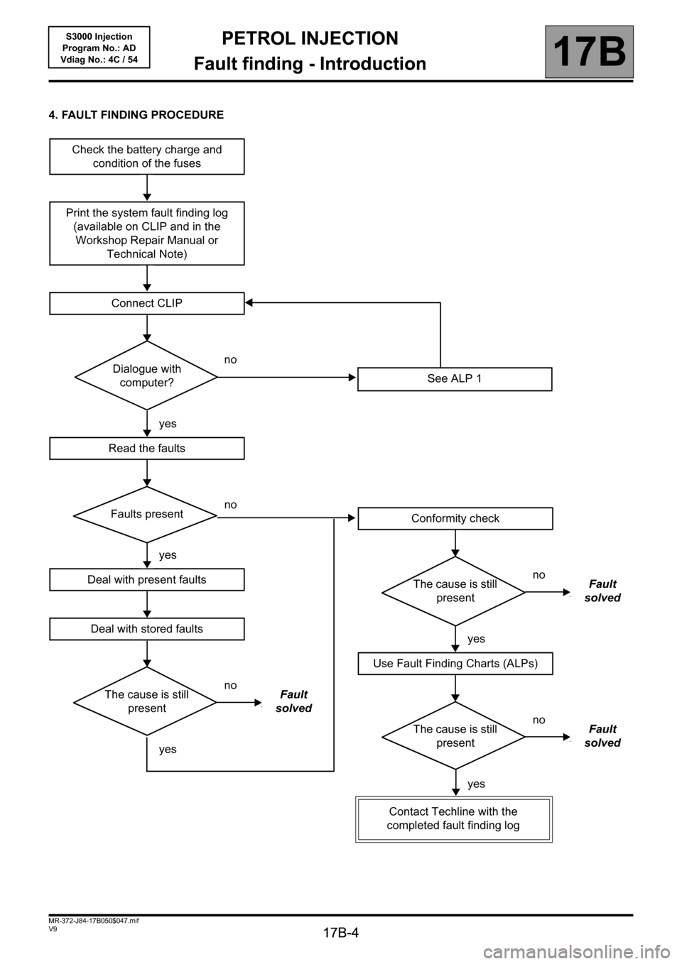
4. FAULT FINDING PROCEDURE
Check the battery charge and
condition of the fuses
Print the system fault finding log
(available on CLIP and in the
Workshop Repair Manual or
Technical Note)
Connect CLIP
no
Dialogue with
computer?
yes
Read the faults
no
Faults present
yes
Deal with present faults
Deal with stored faults
no
The cause is still
presentFault
solved
yes
See ALP 1
Conformity check
no
The cause is still
presentFault
solved
yes
Use Fault Finding Charts (ALPs)
no
The cause is still
presentFault
solved
yes
Contact Techline with the
completed fault finding log
Page 5 of 230

PETROL INJECTION
Fault finding - Introduction
17B
17B-5
PETROL INJECTION
Fault finding - Introduction
17B
17B-5V9 MR-372-J84-17B050$047.mif
S3000 Injection
Program No.: AD
Vdiag No.: 4C / 54
4. FAULT FINDING PROCEDURE (continued)
Wiring check:
Fault finding problems:
Disconnecting the connectors and/or manipulating the wiring may temporarily remove the cause of a fault.
Electrical measurements of the voltage, resistance and insulation are generally correct, especially if the fault is not
present when the analysis is made (stored fault).
Visual inspection:
Look for damage under the bonnet and in the passenger compartment.
Carefully check the fuses, insulation and wiring routing.
Look for signs of oxidation.
Tactile inspection:
While manipulating the wiring, use the diagnostic tool to note any change in fault status from stored to present.
Check that the connectors are correctly tightened, apply light pressure to the connectors, twist the wiring harness.
If there is a change in status, try to locate the source of the fault.
Inspection of each component:
Disconnect the connectors and check the appearance of the clips and tabs, as well as their crimping (no crimping on
the insulating section).
Make sure that the clips and tabs are properly locked in the sockets.
Make sure no clips or tabs have been dislodged during connection.
Check the clip contact pressure using an appropriate model of tab.
Resistance check:
Check the continuity of entire lines, then section by section.
Look for a short circuit to earth, to + 12 V or with another wire.
If a fault is detected, repair or replace the wiring harness.
Page 65 of 230
PETROL INJECTION
Fault finding - Interpretation of faults
17B
17B-65
PETROL INJECTION
Fault finding - Interpretation of faults
17B
17B-65V9 MR-372-J84-17B050$376.mif
S3000 Injection
Program No.: AD
Vdiag No.: 4C / 54
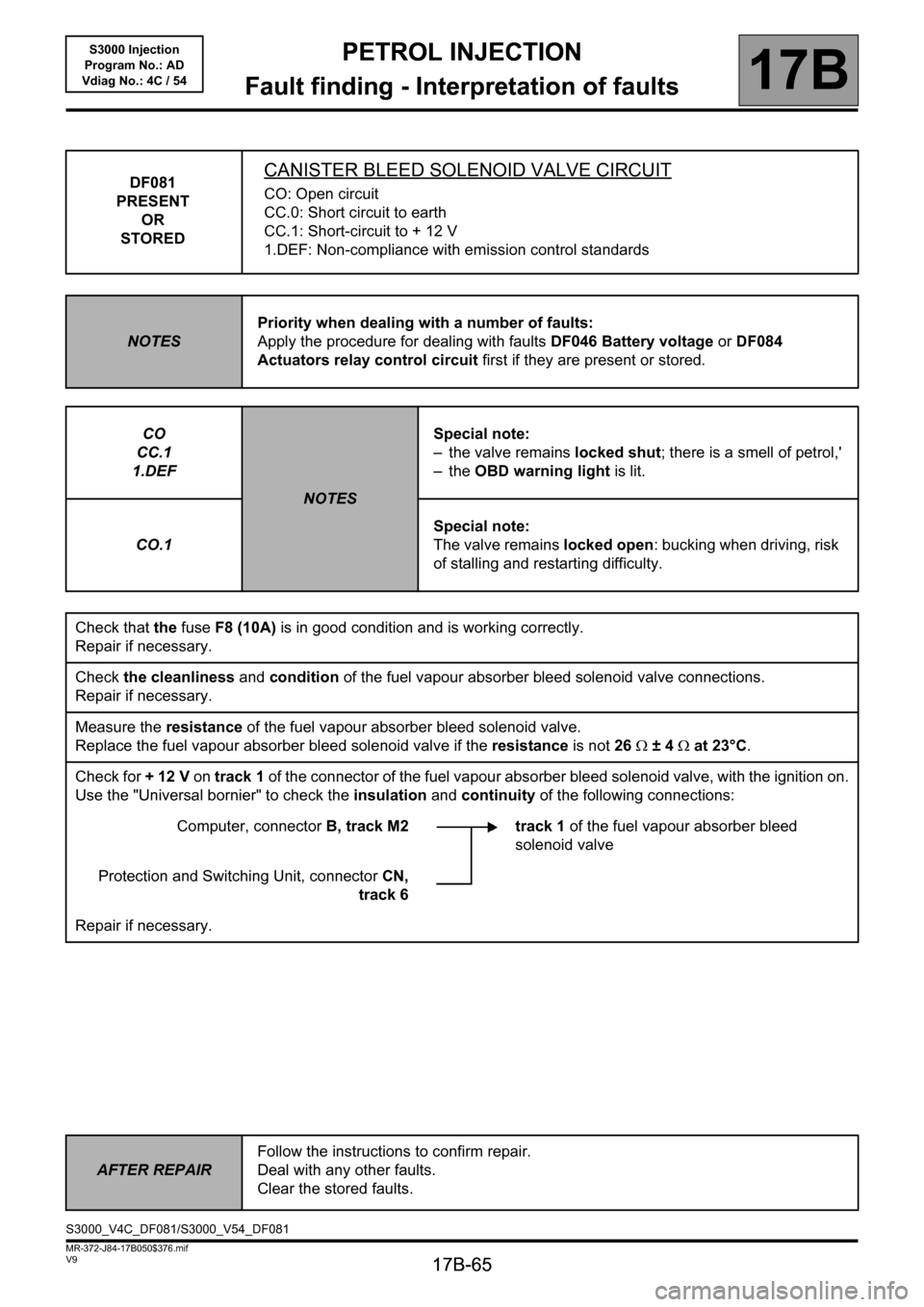
DF081
PRESENT
OR
STOREDCANISTER BLEED SOLENOID VALVE CIRCUIT
CO: Open circuit
CC.0: Short circuit to earth
CC.1: Short-circuit to + 12 V
1.DEF: Non-compliance with emission control standards
NOTESPriority when dealing with a number of faults:
Apply the procedure for dealing with faults DF046 Battery voltage or DF084
Actuators relay control circuit first if they are present or stored.
CO
CC.1
1.DEF
NOTESSpecial note:
– the valve remains locked shut; there is a smell of petrol,'
–the OBD warning light is lit.
CO.1Special note:
The valve remains locked open: bucking when driving, risk
of stalling and restarting difficulty.
Check that the fuseF8 (10A) is in good condition and is working correctly.
Repair if necessary.
Check the cleanliness and condition of the fuel vapour absorber bleed solenoid valve connections.
Repair if necessary.
Measure the resistance of the fuel vapour absorber bleed solenoid valve.
Replace the fuel vapour absorber bleed solenoid valve if the resistance is not 26Ω ±4Ω at 23°C.
Check for + 12 V on track 1 of the connector of the fuel vapour absorber bleed solenoid valve, with the ignition on.
Use the "Universal bornier" to check the insulation and continuity of the following connections:
Computer, connectorB, track M2 track 1 of the fuel vapour absorber bleed
solenoid valve
Protection and Switching Unit, connectorCN,
track 6
Repair if necessary.
AFTER REPAIRFollow the instructions to confirm repair.
Deal with any other faults.
Clear the stored faults.
S3000_V4C_DF081/S3000_V54_DF081
Page 119 of 230
PETROL INJECTION
Fault finding - Interpretation of faults
17B
17B-119
PETROL INJECTION
Fault finding - Interpretation of faults
17B
17B-119V9 MR-372-J84-17B050$423.mif
S3000 Injection
Program No.: AD
Vdiag No.: 4C / 54
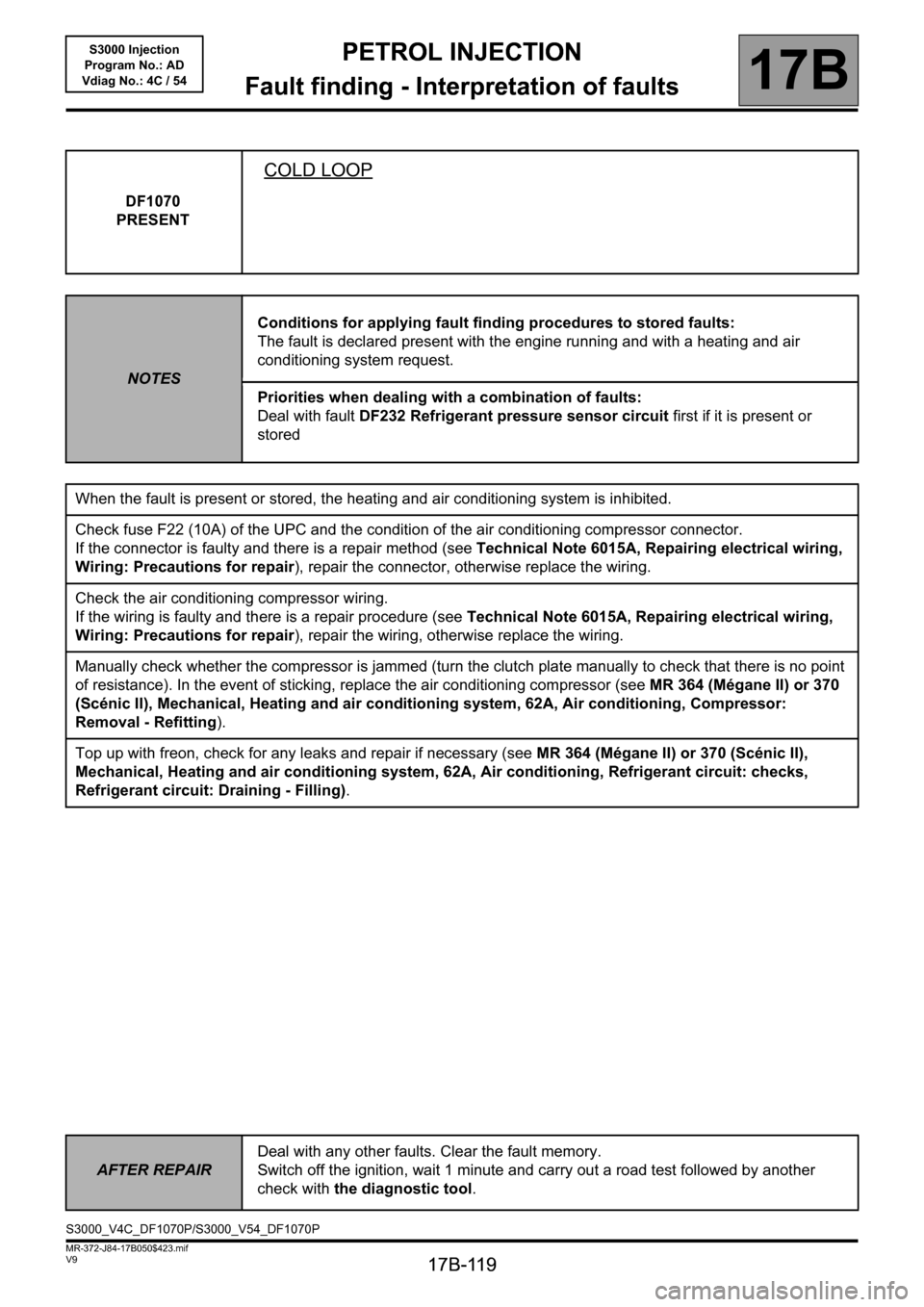
DF1070
PRESENT
COLD LOOP
NOTESConditions for applying fault finding procedures to stored faults:
The fault is declared present with the engine running and with a heating and air
conditioning system request.
Priorities when dealing with a combination of faults:
Deal with fault DF232 Refrigerant pressure sensor circuit first if it is present or
stored
When the fault is present or stored, the heating and air conditioning system is inhibited.
Check fuse F22 (10A) of the UPC and the condition of the air conditioning compressor connector.
If the connector is faulty and there is a repair method (see Technical Note 6015A, Repairing electrical wiring,
Wiring: Precautions for repair), repair the connector, otherwise replace the wiring.
Check the air conditioning compressor wiring.
If the wiring is faulty and there is a repair procedure (see Technical Note 6015A, Repairing electrical wiring,
Wiring: Precautions for repair), repair the wiring, otherwise replace the wiring.
Manually check whether the compressor is jammed (turn the clutch plate manually to check that there is no point
of resistance). In the event of sticking, replace the air conditioning compressor (see MR 364 (Mégane II) or 370
(Scénic II), Mechanical, Heating and air conditioning system, 62A, Air conditioning, Compressor:
Removal - Refitting).
Top up with freon, check for any leaks and repair if necessary (see MR 364 (Mégane II) or 370 (Scénic II),
Mechanical, Heating and air conditioning system, 62A, Air conditioning, Refrigerant circuit: checks,
Refrigerant circuit: Draining - Filling).
AFTER REPAIRDeal with any other faults. Clear the fault memory.
Switch off the ignition, wait 1 minute and carry out a road test followed by another
check with the diagnostic tool.
S3000_V4C_DF1070P/S3000_V54_DF1070P
Page 160 of 230

PETROL INJECTION
Fault finding - Conformity check
17B
17B-160
PETROL INJECTION
Fault finding - Conformity check
17B
17B-160V9 MR-372-J84-17B050$517.mif
S3000 Injection
Program No.: AD
Vdiag No.: 4C / 54
COLD LOOP SUB-FUNCTION:
NOTESOnly perform this conformity check after a complete check with the diagnostic tool.
The values shown in this conformity check are given as a guide.
Application conditions: Engine warm, idling.
Order FunctionParameter or Status
Checked or ActionDisplay and notes Fault finding
1
Air conditioningET079:Air conditioning
presentShows whether or not
the vehicle is equipped
with air conditioning.
YES: Air conditioning is
detected by the injection
computer.
NO: Air conditioning is not
detected by the injection
computer.If inconsistent with
the vehicle
equipment, carry out
a multiplex network
test and apply the
relevant procedure.
2 ET088:Compressor
actuation
requestThe injection requests
the UCH (via the
multiplex network) to
start the compressor.
ACTIVE: The multiplex
network must not be faulty
on the automatic gearbox,
fuse and relay box or UCH
systems. The UCH must
send a compressor
starting request to the
injection. The coolant
pressure sensor must not
be defective. Satisfactory
engine operating
conditions (coolant
temperature, engine load,
etc.).
INACTIVE: One of the
above conditions has not
been met.WITHOUT
3 ET004:Air conditioning
authorisationYES
NO
Page 182 of 230
PETROL INJECTION
Fault finding - Interpretation of statuses
17B
17B - 182
PETROL INJECTION
Fault finding - Interpretation of statuses
17B
17B - 182V9 MR-372-J84-17B050$611.mif
S3000 Injection
Program No.: AD
Vdiag No.: 4C / 54
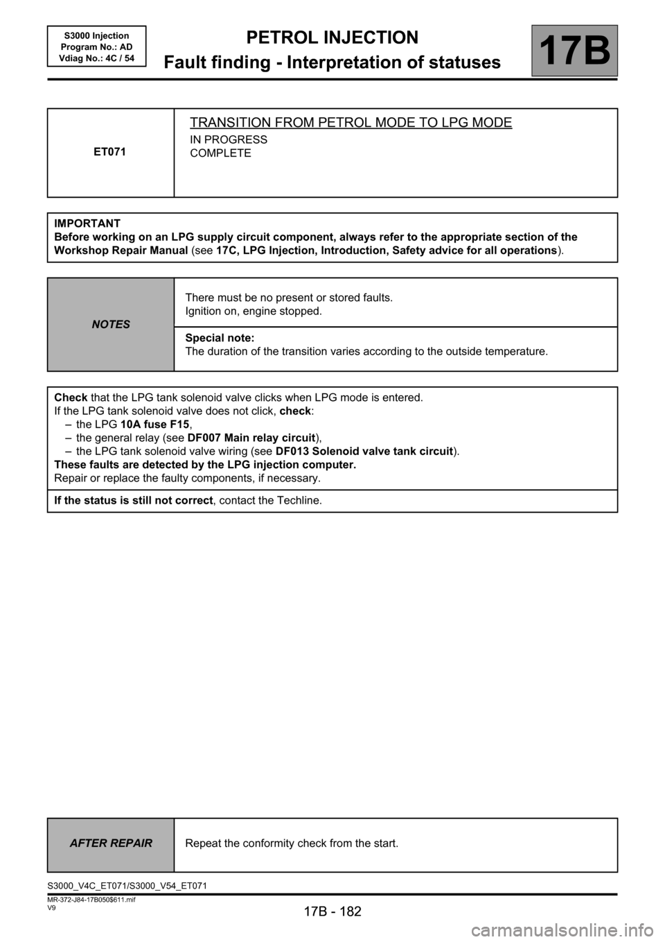
ET071
TRANSITION FROM PETROL MODE TO LPG MODE
IN PROGRESS
COMPLETE
IMPORTANT
Before working on an LPG supply circuit component, always refer to the appropriate section of the
Workshop Repair Manual (see17C, LPG Injection, Introduction, Safety advice for all operations).
NOTESThere must be no present or stored faults.
Ignition on, engine stopped.
Special note:
The duration of the transition varies according to the outside temperature.
Check that the LPG tank solenoid valve clicks when LPG mode is entered.
If the LPG tank solenoid valve does not click, check:
– the LPG 10A fuse F15,
– the general relay (see DF007 Main relay circuit),
– the LPG tank solenoid valve wiring (see DF013 Solenoid valve tank circuit).
These faults are detected by the LPG injection computer.
Repair or replace the faulty components, if necessary.
If the status is still not correct, contact the Techline.
AFTER REPAIRRepeat the conformity check from the start.
S3000_V4C_ET071/S3000_V54_ET071
Page 201 of 230
PETROL INJECTION
Fault finding - Interpretation of statuses
17B
17B - 201
PETROL INJECTION
Fault finding - Interpretation of statuses
17B
17B - 201V9 MR-372-J84-17B050$611.mif
S3000 Injection
Program No.: AD
Vdiag No.: 4C / 54
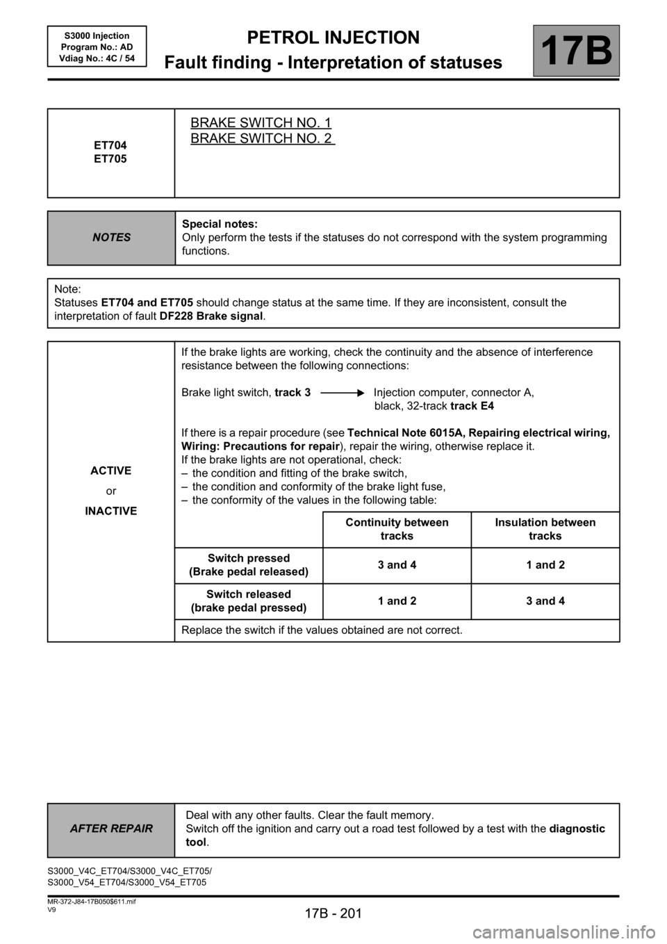
ET704
ET705
BRAKE SWITCH NO. 1
BRAKE SWITCH NO. 2
NOTESSpecial notes:
Only perform the tests if the statuses do not correspond with the system programming
functions.
Note:
Statuses ET704 and ET705 should change status at the same time. If they are inconsistent, consult the
interpretation of fault DF228 Brake signal.
ACTIVE
or
INACTIVEIf the brake lights are working, check the continuity and the absence of interference
resistance between the following connections:
Brake light switch, track 3 Injection computer, connector A,
black, 32-track track E4
If there is a repair procedure (see Technical Note 6015A, Repairing electrical wiring,
Wiring: Precautions for repair), repair the wiring, otherwise replace it.
If the brake lights are not operational, check:
– the condition and fitting of the brake switch,
– the condition and conformity of the brake light fuse,
– the conformity of the values in the following table:
Continuity between
tracksInsulation between
tracks
Switch pressed
(Brake pedal released)3 and 4 1 and 2
Switch released
(brake pedal pressed)1 and 2 3 and 4
Replace the switch if the values obtained are not correct.
AFTER REPAIRDeal with any other faults. Clear the fault memory.
Switch off the ignition and carry out a road test followed by a test with the diagnostic
tool.
S3000_V4C_ET704/S3000_V4C_ET705/
S3000_V54_ET704/S3000_V54_ET705
Page 225 of 230
PETROL INJECTION
Fault finding - Fault Finding Chart
17B
17B-225
PETROL INJECTION
Fault finding - Fault Finding Chart
17B
17B-225V9 MR-372-J84-17B050$940.mif
S3000 Injection
Program No.: AD
Vdiag No.:4C / 54PETROL INJECTION
Fault finding - Fault Finding Chart
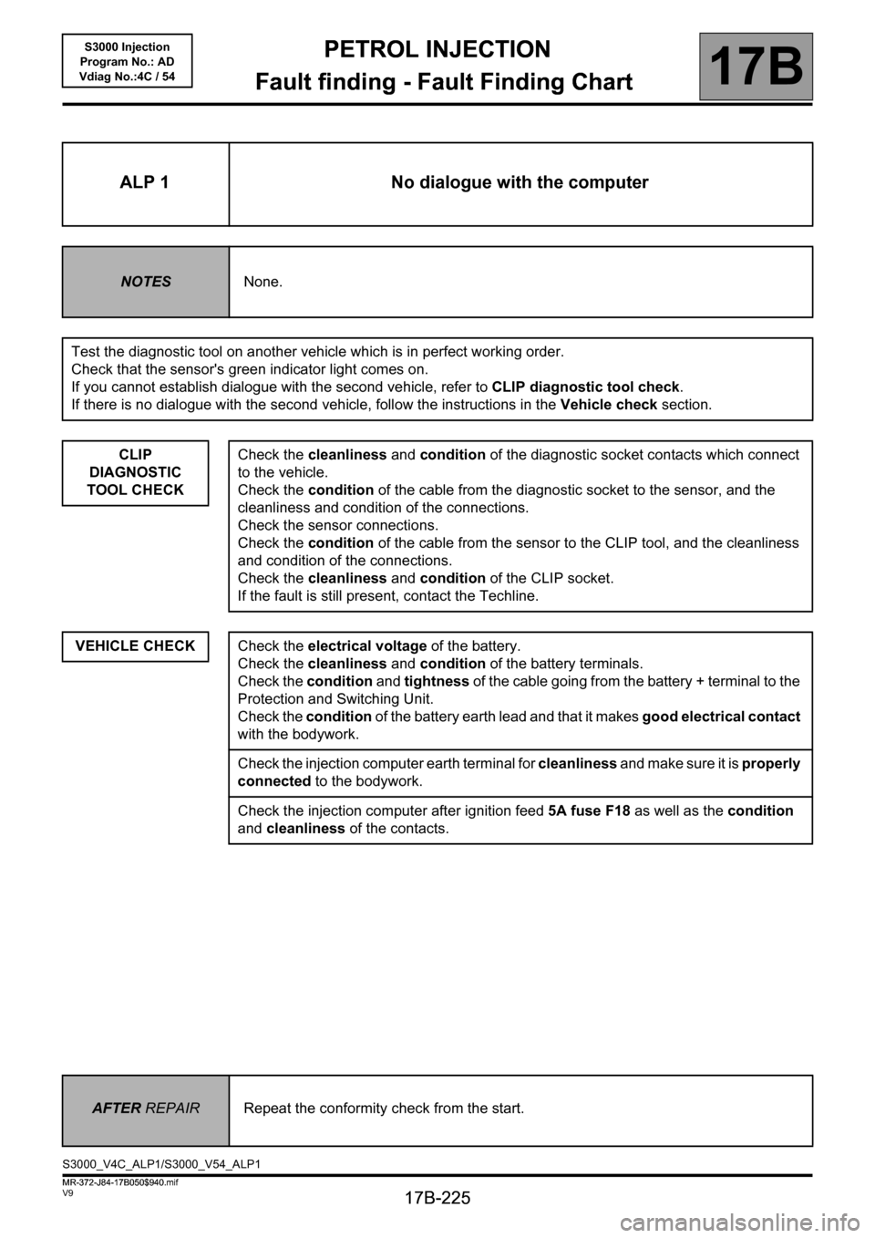
ALP 1 No dialogue with the computer
NOTESNone.
Test the diagnostic tool on another vehicle which is in perfect working order.
Check that the sensor's green indicator light comes on.
If you cannot establish dialogue with the second vehicle, refer to CLIP diagnostic tool check.
If there is no dialogue with the second vehicle, follow the instructions in the Vehicle check section.
CLIP
DIAGNOSTIC
TOOL CHECK
VEHICLE CHECK
Check the cleanliness and condition of the diagnostic socket contacts which connect
to the vehicle.
Check the condition of the cable from the diagnostic socket to the sensor, and the
cleanliness and condition of the connections.
Check the sensor connections.
Check the condition of the cable from the sensor to the CLIP tool, and the cleanliness
and condition of the connections.
Check the cleanliness and condition of the CLIP socket.
If the fault is still present, contact the Techline.
Check the electrical voltage of the battery.
Check the cleanliness and condition of the battery terminals.
Check the condition and tightness of the cable going from the battery + terminal to the
Protection and Switching Unit.
Check the condition of the battery earth lead and that it makes good electrical contact
with the bodywork.
Check the injection computer earth terminal for cleanliness and make sure it is properly
connected to the bodywork.
Check the injection computer after ignition feed 5A fuse F18 as well as the condition
and cleanliness of the contacts.
AFTER REPAIRRepeat the conformity check from the start.
S3000_V4C_ALP1/S3000_V54_ALP1
MR-372-J84-17B050$940.mif
Page 227 of 230
PETROL INJECTION
Fault finding - Fault Finding Chart
17B
17B-227
PETROL INJECTION
Fault finding - Fault Finding Chart
17B
17B-227V9 MR-372-J84-17B050$940.mif
S3000 Injection
Program No.: AD
Vdiag No.:4C / 54
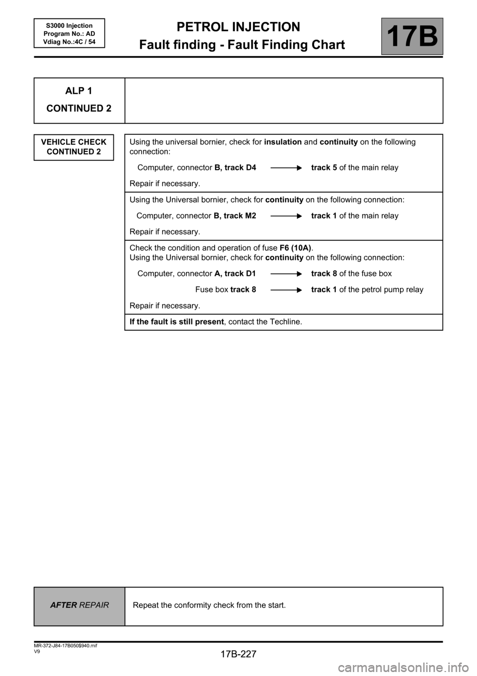
ALP 1
CONTINUED 2
VEHICLE CHECK
CONTINUED 2Using the universal bornier, check for insulation and continuity on the following
connection:
Computer, connectorB, track D4 track 5 of the main relay
Repair if necessary.
Using the Universal bornier, check for continuity on the following connection:
Computer, connectorB, track M2 track 1 of the main relay
Repair if necessary.
Check the condition and operation of fuse F6 (10A).
Using the Universal bornier, check for continuity on the following connection:
Computer, connector A, track D1 track 8 of the fuse box
Fuse box track8 track1 of the petrol pump relay
Repair if necessary.
If the fault is still present, contact the Techline.
AFTER REPAIRRepeat the conformity check from the start.