charging RENAULT SCENIC 2012 J95 / 3.G Engine And Peripherals EDC16CP33 User Guide
[x] Cancel search | Manufacturer: RENAULT, Model Year: 2012, Model line: SCENIC, Model: RENAULT SCENIC 2012 J95 / 3.GPages: 510, PDF Size: 2.98 MB
Page 104 of 510
13B-104
AFTER REPAIRDeal with any other faults. Clear the fault memory.
Switch off the ignition until the end of the power-latch phase, and carry out a road test
followed by a check with the diagnostic tool.
V12 MR-372-J84-13B300$072.mif
DIESEL INJECTION
Fault finding – Interpretation of faults13B
EDC16CP33
Program No.: C4
Vdiag No.: 04, 08, 18, 1C,
20, 24, 26, 28, 34, 38, 44,
4C, 54, 58, 5C, 60, 62, 74
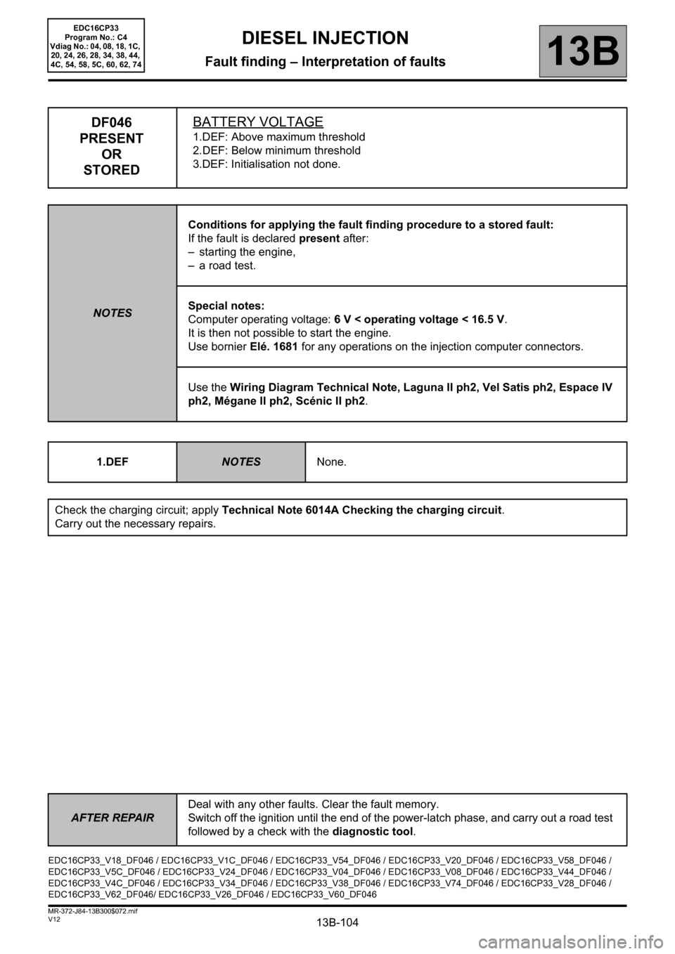
DF046
PRESENT
OR
STOREDBATTERY VOLTAGE
1.DEF: Above maximum threshold
2.DEF: Below minimum threshold
3.DEF: Initialisation not done.
NOTESConditions for applying the fault finding procedure to a stored fault:
If the fault is declared present after:
– starting the engine,
– a road test.
Special notes:
Computer operating voltage: 6 V < operating voltage < 16.5 V.
It is then not possible to start the engine.
Use bornier Elé. 1681 for any operations on the injection computer connectors.
Use the Wiring Diagram Technical Note, Laguna II ph2, Vel Satis ph2, Espace IV
ph2, Mégane II ph2, Scénic II ph2.
1.DEF
NOTESNone.
Check the charging circuit; apply Technical Note 6014A Checking the charging circuit.
Carry out the necessary repairs.
EDC16CP33_V18_DF046 / EDC16CP33_V1C_DF046 / EDC16CP33_V54_DF046 / EDC16CP33_V20_DF046 / EDC16CP33_V58_DF046 /
EDC16CP33_V5C_DF046 / EDC16CP33_V24_DF046 / EDC16CP33_V04_DF046 / EDC16CP33_V08_DF046 / EDC16CP33_V44_DF046 /
EDC16CP33_V4C_DF046 / EDC16CP33_V34_DF046 / EDC16CP33_V38_DF046 / EDC16CP33_V74_DF046 / EDC16CP33_V28_DF046 /
EDC16CP33_V62_DF046/ EDC16CP33_V26_DF046 / EDC16CP33_V60_DF046
Page 105 of 510
13B-105
AFTER REPAIRDeal with any other faults. Clear the fault memory.
Switch off the ignition until the end of the power-latch phase, and carry out a road test
followed by a check with the diagnostic tool.
V12 MR-372-J84-13B300$072.mif
DIESEL INJECTION
Fault finding – Interpretation of faults13B
EDC16CP33
Program No.: C4
Vdiag No.: 04, 08, 18, 1C,
20, 24, 26, 28, 34, 38, 44,
4C, 54, 58, 5C, 60, 62, 74
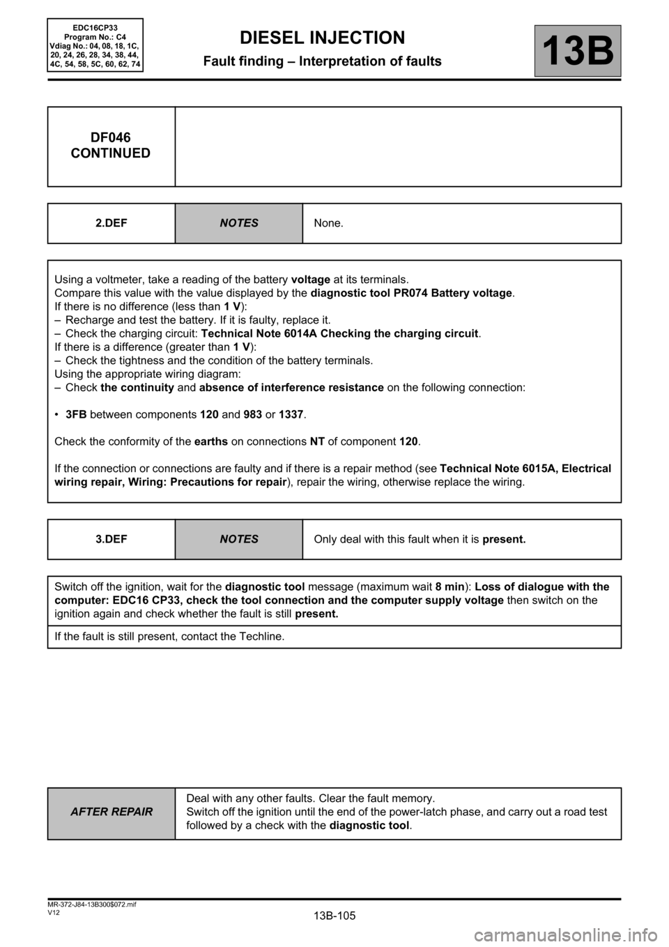
DF046
CONTINUED
2.DEFNOTESNone.
Using a voltmeter, take a reading of the battery voltage at its terminals.
Compare this value with the value displayed by the diagnostic tool PR074 Battery voltage.
If there is no difference (less than 1 V):
– Recharge and test the battery. If it is faulty, replace it.
– Check the charging circuit: Technical Note 6014A Checking the charging circuit.
If there is a difference (greater than 1 V):
– Check the tightness and the condition of the battery terminals.
Using the appropriate wiring diagram:
–Check the continuity and absence of interference resistance on the following connection:
•3FB between components 120 and 983 or 1337.
Check the conformity of the earths on connections NT of component 120.
If the connection or connections are faulty and if there is a repair method (see Technical Note 6015A, Electrical
wiring repair, Wiring: Precautions for repair), repair the wiring, otherwise replace the wiring.
3.DEF
NOTESOnly deal with this fault when it is present.
Switch off the ignition, wait for the diagnostic tool message (maximum wait 8 min): Loss of dialogue with the
computer: EDC16 CP33, check the tool connection and the computer supply voltage then switch on the
ignition again and check whether the fault is still present.
If the fault is still present, contact the Techline.
Page 111 of 510
13B-111
AFTER REPAIRDeal with any other faults. Clear the fault memory.
Switch off the ignition until the end of the power-latch phase, and carry out a road test
followed by a check with the diagnostic tool.
V12 MR-372-J84-13B300$072.mif
DIESEL INJECTION
Fault finding – Interpretation of faults13B
EDC16CP33
Program No.: C4
Vdiag No.: 04, 08, 18, 1C,
20, 24, 26, 28, 34, 38, 44,
4C, 54, 58, 5C, 60, 62, 74
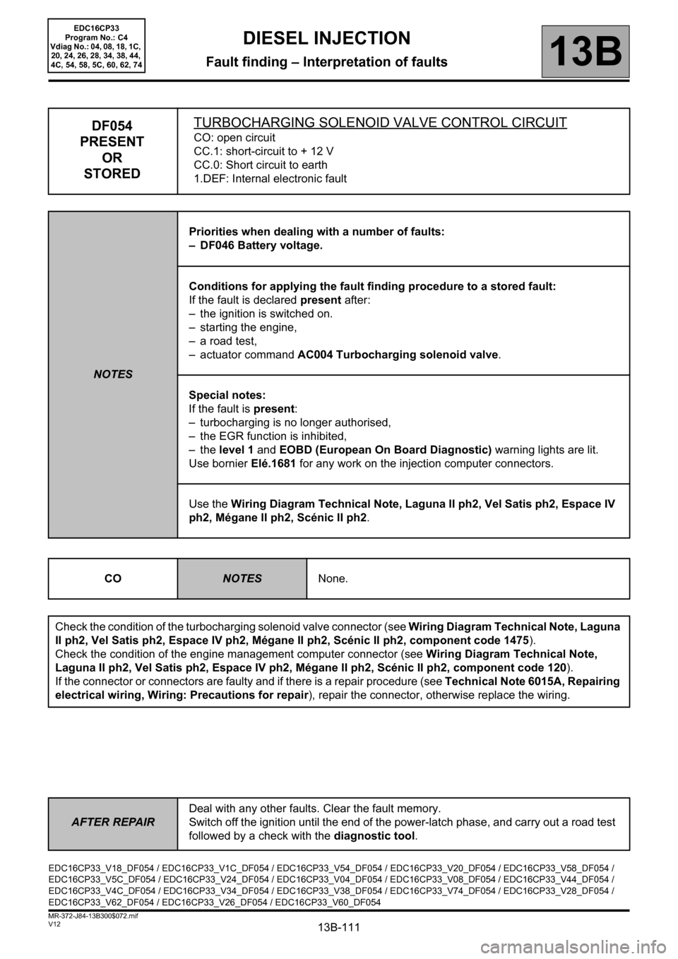
DF054
PRESENT
OR
STOREDTURBOCHARGING SOLENOID VALVE CONTROL CIRCUITCO: open circuit
CC.1: short-circuit to + 12 V
CC.0: Short circuit to earth
1.DEF: Internal electronic fault
NOTESPriorities when dealing with a number of faults:
– DF046 Battery voltage.
Conditions for applying the fault finding procedure to a stored fault:
If the fault is declared present after:
– the ignition is switched on.
– starting the engine,
– a road test,
– actuator command AC004 Turbocharging solenoid valve.
Special notes:
If the fault is present:
– turbocharging is no longer authorised,
– the EGR function is inhibited,
–the level 1 and EOBD (European On Board Diagnostic) warning lights are lit.
Use bornier Elé.1681 for any work on the injection computer connectors.
Use the Wiring Diagram Technical Note, Laguna II ph2, Vel Satis ph2, Espace IV
ph2, Mégane II ph2, Scénic II ph2.
CO
NOTESNone.
Check the condition of the turbocharging solenoid valve connector (see Wiring Diagram Technical Note, Laguna
II ph2, Vel Satis ph2, Espace IV ph2, Mégane II ph2, Scénic II ph2, component code 1475).
Check the condition of the engine management computer connector (see Wiring Diagram Technical Note,
Laguna II ph2, Vel Satis ph2, Espace IV ph2, Mégane II ph2, Scénic II ph2, component code 120).
If the connector or connectors are faulty and if there is a repair procedure (see Technical Note 6015A, Repairing
electrical wiring, Wiring: Precautions for repair), repair the connector, otherwise replace the wiring.
EDC16CP33_V18_DF054 / EDC16CP33_V1C_DF054 / EDC16CP33_V54_DF054 / EDC16CP33_V20_DF054 / EDC16CP33_V58_DF054 /
EDC16CP33_V5C_DF054 / EDC16CP33_V24_DF054 / EDC16CP33_V04_DF054 / EDC16CP33_V08_DF054 / EDC16CP33_V44_DF054 /
EDC16CP33_V4C_DF054 / EDC16CP33_V34_DF054 / EDC16CP33_V38_DF054 / EDC16CP33_V74_DF054 / EDC16CP33_V28_DF054 /
EDC16CP33_V62_DF054 / EDC16CP33_V26_DF054 / EDC16CP33_V60_DF054
Page 112 of 510
13B-112
AFTER REPAIRDeal with any other faults. Clear the fault memory.
Switch off the ignition until the end of the power-latch phase, and carry out a road test
followed by a check with the diagnostic tool.
V12 MR-372-J84-13B300$072.mif
DIESEL INJECTION
Fault finding – Interpretation of faults13B
EDC16CP33
Program No.: C4
Vdiag No.: 04, 08, 18, 1C,
20, 24, 26, 28, 34, 38, 44,
4C, 54, 58, 5C, 60, 62, 74
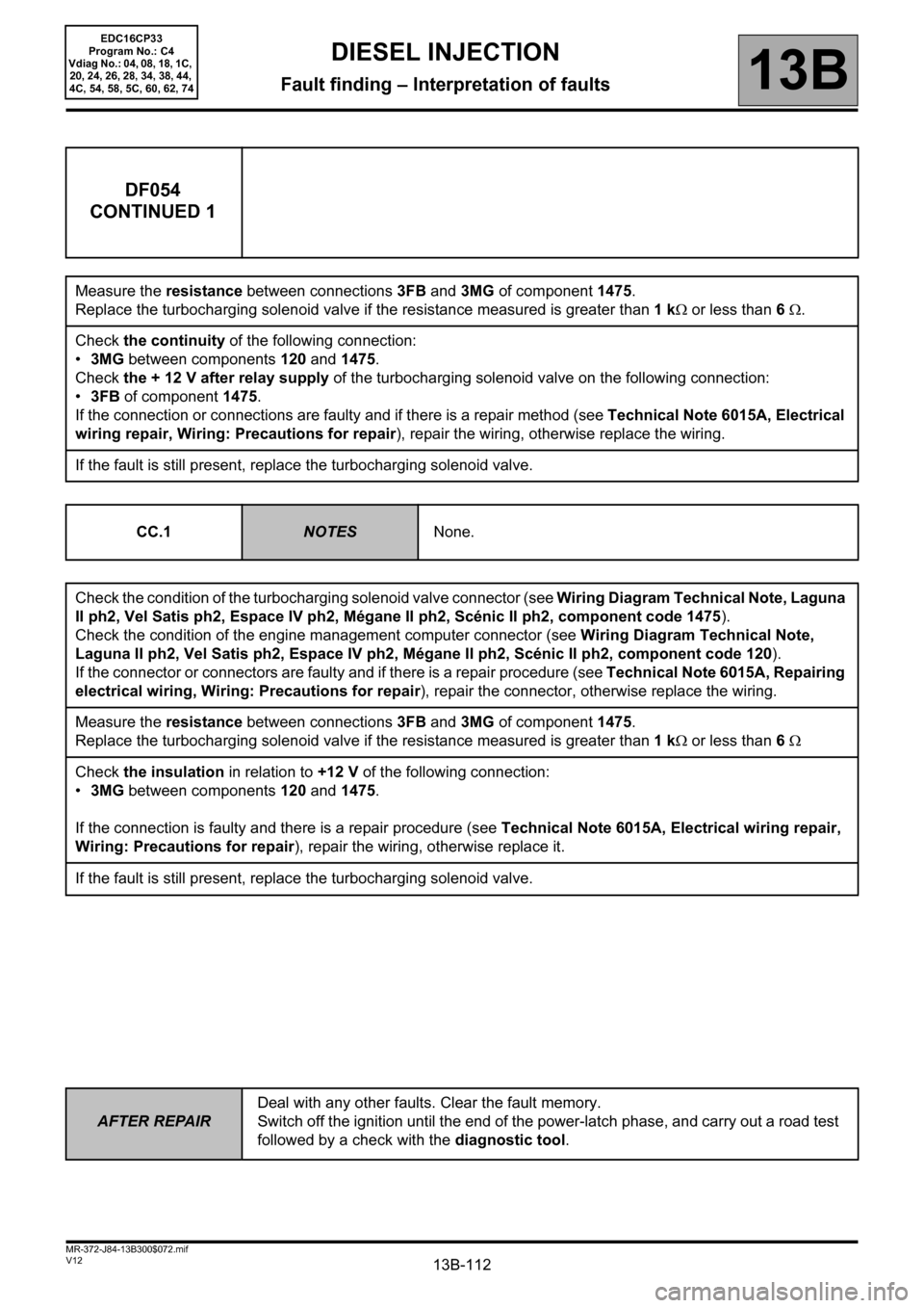
DF054
CONTINUED 1
Measure the resistance between connections3FB and 3MG of component1475.
Replace the turbocharging solenoid valve if the resistance measured is greater than 1 kΩ or less than 6 Ω.
Check the continuity of the following connection:
•3MG between components 120 and 1475.
Check the + 12 V after relay supply of the turbocharging solenoid valve on the following connection:
•3FB of component 1475.
If the connection or connections are faulty and if there is a repair method (see Technical Note 6015A, Electrical
wiring repair, Wiring: Precautions for repair), repair the wiring, otherwise replace the wiring.
If the fault is still present, replace the turbocharging solenoid valve.
CC.1
NOTESNone.
Check the condition of the turbocharging solenoid valve connector (see Wiring Diagram Technical Note, Laguna
II ph2, Vel Satis ph2, Espace IV ph2, Mégane II ph2, Scénic II ph2, component code 1475).
Check the condition of the engine management computer connector (see Wiring Diagram Technical Note,
Laguna II ph2, Vel Satis ph2, Espace IV ph2, Mégane II ph2, Scénic II ph2, component code 120).
If the connector or connectors are faulty and if there is a repair procedure (see Technical Note 6015A, Repairing
electrical wiring, Wiring: Precautions for repair), repair the connector, otherwise replace the wiring.
Measure the resistance between connections3FB and 3MG of component1475.
Replace the turbocharging solenoid valve if the resistance measured is greater than 1 kΩ or less than 6 Ω
Check the insulation in relation to +12 V of the following connection:
•3MG between components 120 and 1475.
If the connection is faulty and there is a repair procedure (see Technical Note 6015A, Electrical wiring repair,
Wiring: Precautions for repair), repair the wiring, otherwise replace it.
If the fault is still present, replace the turbocharging solenoid valve.
Page 113 of 510
13B-113
AFTER REPAIRDeal with any other faults. Clear the fault memory.
Switch off the ignition until the end of the power-latch phase, and carry out a road test
followed by a check with the diagnostic tool.
V12 MR-372-J84-13B300$072.mif
DIESEL INJECTION
Fault finding – Interpretation of faults13B
EDC16CP33
Program No.: C4
Vdiag No.: 04, 08, 18, 1C,
20, 24, 26, 28, 34, 38, 44,
4C, 54, 58, 5C, 60, 62, 74
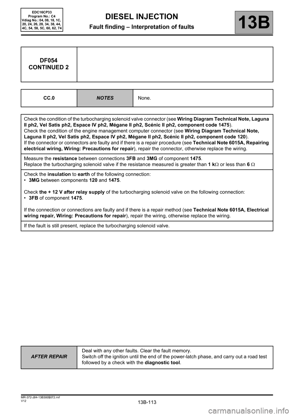
DF054
CONTINUED 2
CC.0NOTESNone.
Check the condition of the turbocharging solenoid valve connector (see Wiring Diagram Technical Note, Laguna
II ph2, Vel Satis ph2, Espace IV ph2, Mégane II ph2, Scénic II ph2, component code 1475).
Check the condition of the engine management computer connector (see Wiring Diagram Technical Note,
Laguna II ph2, Vel Satis ph2, Espace IV ph2, Mégane II ph2, Scénic II ph2, component code 120).
If the connector or connectors are faulty and if there is a repair procedure (see Technical Note 6015A, Repairing
electrical wiring, Wiring: Precautions for repair), repair the connector, otherwise replace the wiring.
Measure the resistance between connections3FB and 3MG of component1475.
Replace the turbocharging solenoid valve if the resistance measured is greater than 1 kΩ or less than 6 Ω
Check the insulation to earth of the following connection:
•3MG between components 120 and 1475.
Check the + 12 V after relay supply of the turbocharging solenoid valve on the following connection:
•3FB of component 1475.
If the connection or connections are faulty and if there is a repair method (see Technical Note 6015A, Electrical
wiring repair, Wiring: Precautions for repair), repair the wiring, otherwise replace the wiring.
If the fault is still present, replace the turbocharging solenoid valve.
Page 114 of 510
13B-114
AFTER REPAIRDeal with any other faults. Clear the fault memory.
Switch off the ignition until the end of the power-latch phase, and carry out a road test
followed by a check with the diagnostic tool.
V12 MR-372-J84-13B300$072.mif
DIESEL INJECTION
Fault finding – Interpretation of faults13B
EDC16CP33
Program No.: C4
Vdiag No.: 04, 08, 18, 1C,
20, 24, 26, 28, 34, 38, 44,
4C, 54, 58, 5C, 60, 62, 74
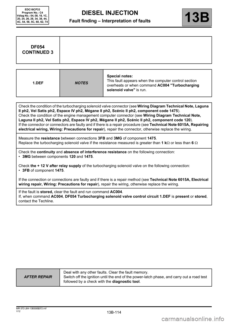
DF054
CONTINUED 3
1.DEFNOTESSpecial notes:
This fault appears when the computer control section
overheats or when command AC004 "Turbocharging
solenoid valve" is run.
Check the condition of the turbocharging solenoid valve connector (see Wiring Diagram Technical Note, Laguna
II ph2, Vel Satis ph2, Espace IV ph2, Mégane II ph2, Scénic II ph2, component code 1475).
Check the condition of the engine management computer connector (see Wiring Diagram Technical Note,
Laguna II ph2, Vel Satis ph2, Espace IV ph2, Mégane II ph2, Scénic II ph2, component code 120).
If the connector or connectors are faulty and if there is a repair procedure (see Technical Note 6015A, Repairing
electrical wiring, Wiring: Precautions for repair), repair the connector, otherwise replace the wiring.
Measure the resistance between connections3FB and 3MG of component1475.
Replace the turbocharging solenoid valve if the resistance measured is greater than 1 kΩ or less than 6 Ω
Check the continuity and absence of interference resistance on the following connection:
•3MG between components 120 and 1475.
Check the + 12 V after relay supply of the turbocharging solenoid valve on the following connection:
•3FB of component 1475.
If the connection or connections are faulty and if there is a repair method (see Technical Note 6015A, Electrical
wiring repair, Wiring: Precautions for repair), repair the wiring, otherwise replace the wiring.
If the fault is stored, clear the fault and run command AC004.
If, when command AC004, DF054 Turbocharging solenoid valve control circuit 1.DEF is present or stored,
contact the Techline.
Page 115 of 510
13B-115
AFTER REPAIRDeal with any other faults. Clear the fault memory.
Switch off the ignition until the end of the power-latch phase, and carry out a road test
followed by a check with the diagnostic tool.
V12 MR-372-J84-13B300$072.mif
DIESEL INJECTION
Fault finding – Interpretation of faults13B
EDC16CP33
Program No.: C4
Vdiag No.: 04, 08, 18, 1C,
20, 24, 26, 28, 34, 38, 44,
4C, 54, 58, 5C, 60, 62, 74
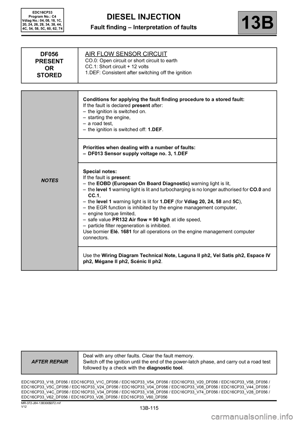
DF056
PRESENT
OR
STOREDAIR FLOW SENSOR CIRCUIT
CO.0: Open circuit or short circuit to earth
CC.1: Short circuit + 12 volts
1.DEF: Consistent after switching off the ignition
NOTESConditions for applying the fault finding procedure to a stored fault:
If the fault is declared present after:
– the ignition is switched on.
– starting the engine,
– a road test,
– the ignition is switched off: 1.DEF.
Priorities when dealing with a number of faults:
– DF013 Sensor supply voltage no. 3, 1.DEF
Special notes:
If the fault is present:
–the EOBD (European On Board Diagnostic) warning light is lit,
–the level 1 warning light is lit and turbocharging is no longer authorised for CO.0 and
CC.1,
–the level 1 warning light is lit for 1.DEF (for Vdiag 20, 24, 58 and 5C),
– the EGR function is inhibited by the engine management computer,
– engine torque limited,
– safe value PR132 Air flow = 90 kg/h at idle speed,
– particle filter regeneration is inhibited.
Use bornier Elé. 1681 for all operations on the engine management computer
connectors.
Use the Wiring Diagram Technical Note, Laguna II ph2, Vel Satis ph2, Espace IV
ph2, Mégane II ph2, Scénic II ph2.
EDC16CP33_V18_DF056 / EDC16CP33_V1C_DF056 / EDC16CP33_V54_DF056 / EDC16CP33_V20_DF056 / EDC16CP33_V58_DF056 /
EDC16CP33_V5C_DF056 / EDC16CP33_V24_DF056 / EDC16CP33_V04_DF056 / EDC16CP33_V08_DF056 / EDC16CP33_V44_DF056 /
EDC16CP33_V4C_DF056 / EDC16CP33_V34_DF056 / EDC16CP33_V38_DF056 / EDC16CP33_V74_DF056 / EDC16CP33_V28_DF056 /
EDC16CP33_V62_DF056 / EDC16CP33_V26_DF056 / EDC16CP33_V60_DF056
Page 118 of 510
13B-118
AFTER REPAIRDeal with any other faults. Clear the fault memory.
Switch off the ignition until the end of the power-latch phase, and carry out a road test
followed by a check with the diagnostic tool.
V12 MR-372-J84-13B300$072.mif
DIESEL INJECTION
Fault finding – Interpretation of faults13B
EDC16CP33
Program No.: C4
Vdiag No.: 04, 08, 18, 1C,
20, 24, 26, 28, 34, 38, 44,
4C, 54, 58, 5C, 60, 62, 74
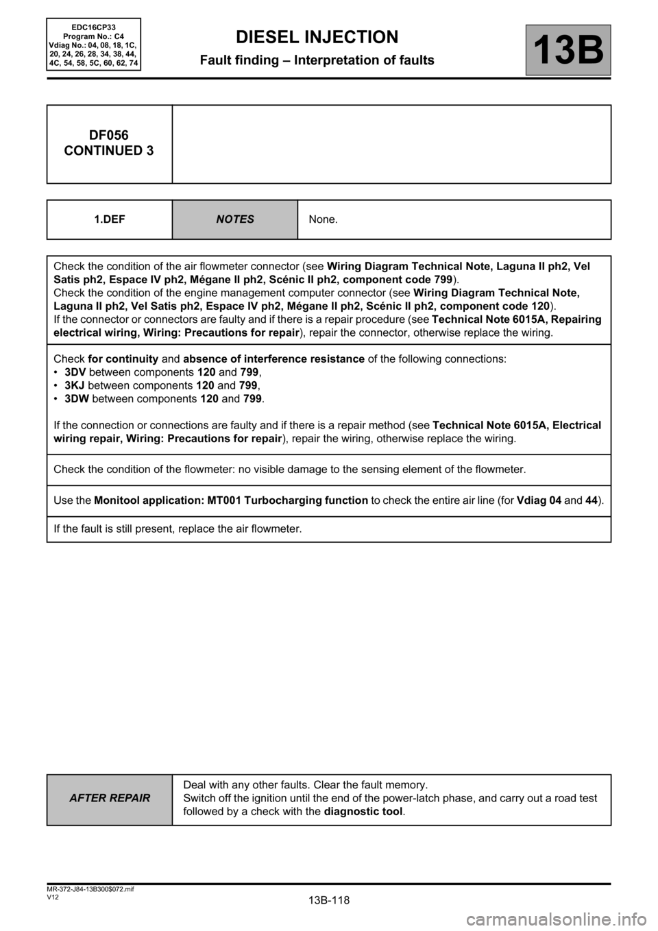
DF056
CONTINUED 3
1.DEFNOTESNone.
Check the condition of the air flowmeter connector (see Wiring Diagram Technical Note, Laguna II ph2, Vel
Satis ph2, Espace IV ph2, Mégane II ph2, Scénic II ph2, component code 799).
Check the condition of the engine management computer connector (see Wiring Diagram Technical Note,
Laguna II ph2, Vel Satis ph2, Espace IV ph2, Mégane II ph2, Scénic II ph2, component code 120).
If the connector or connectors are faulty and if there is a repair procedure (see Technical Note 6015A, Repairing
electrical wiring, Wiring: Precautions for repair), repair the connector, otherwise replace the wiring.
Check for continuity and absence of interference resistance of the following connections:
•3DV between components 120 and 799,
•3KJ between components 120 and 799,
•3DW between components 120 and 799.
If the connection or connections are faulty and if there is a repair method (see Technical Note 6015A, Electrical
wiring repair, Wiring: Precautions for repair), repair the wiring, otherwise replace the wiring.
Check the condition of the flowmeter: no visible damage to the sensing element of the flowmeter.
Use the Monitool application: MT001 Turbocharging function to check the entire air line (for Vdiag 04 and 44).
If the fault is still present, replace the air flowmeter.
Page 148 of 510
13B-148
AFTER REPAIRDeal with any other faults. Clear the fault memory.
Switch off the ignition until the end of the power-latch phase, and carry out a road test
followed by a check with the diagnostic tool.
V12 MR-372-J84-13B300$073.mif
DIESEL INJECTION
Fault finding – Interpretation of faults13B
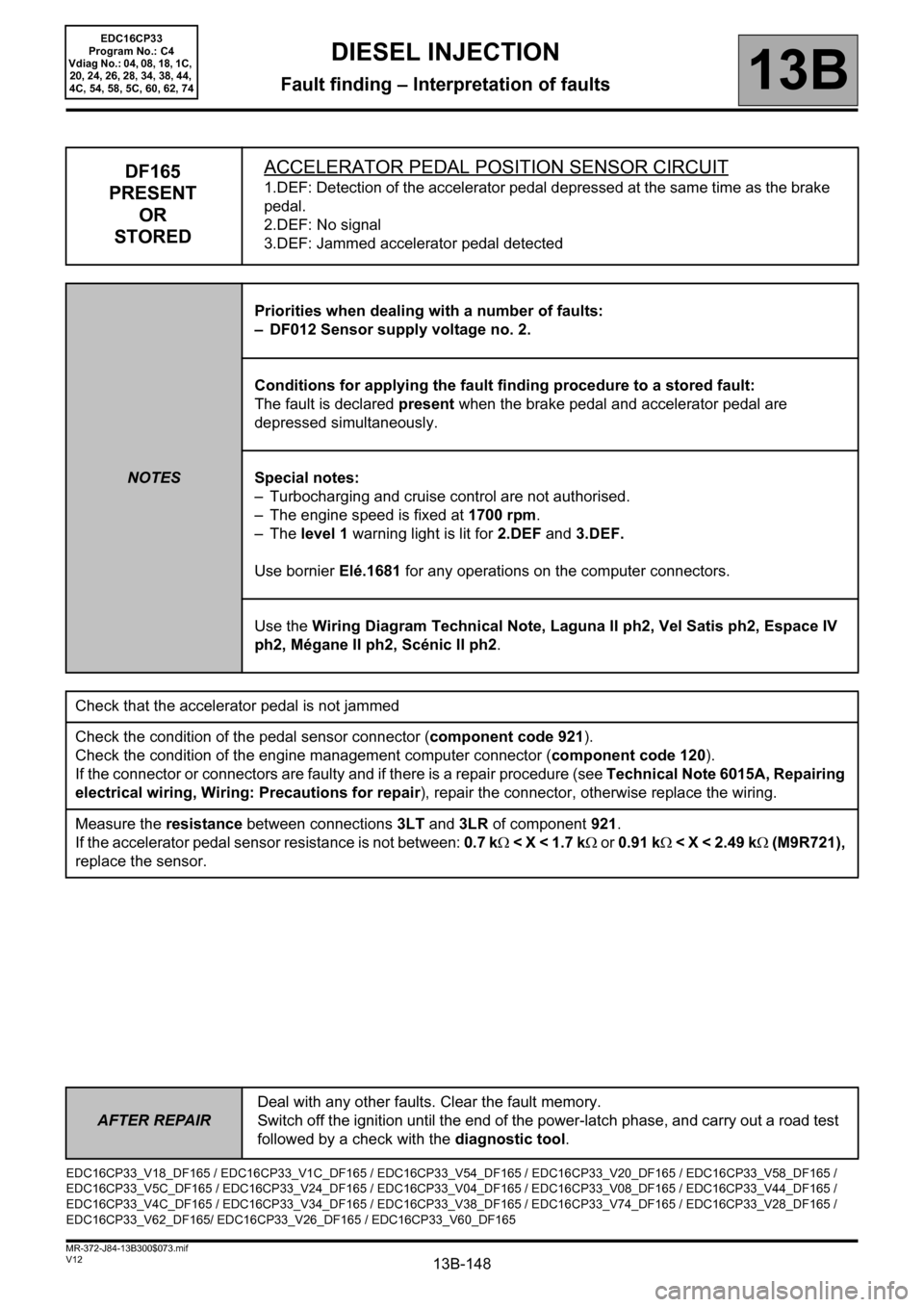
DF165
PRESENT
OR
STOREDACCELERATOR PEDAL POSITION SENSOR CIRCUIT1.DEF: Detection of the accelerator pedal depressed at the same time as the brake
pedal.
2.DEF: No signal
3.DEF: Jammed accelerator pedal detected
NOTESPriorities when dealing with a number of faults:
– DF012 Sensor supply voltage no. 2.
Conditions for applying the fault finding procedure to a stored fault:
The fault is declared present when the brake pedal and accelerator pedal are
depressed simultaneously.
Special notes:
– Turbocharging and cruise control are not authorised.
– The engine speed is fixed at 1700 rpm.
–The level 1 warning light is lit for 2.DEF and 3.DEF.
Use bornier Elé.1681 for any operations on the computer connectors.
Use the Wiring Diagram Technical Note, Laguna II ph2, Vel Satis ph2, Espace IV
ph2, Mégane II ph2, Scénic II ph2.
Check that the accelerator pedal is not jammed
Check the condition of the pedal sensor connector (component code 921).
Check the condition of the engine management computer connector (component code 120).
If the connector or connectors are faulty and if there is a repair procedure (see Technical Note 6015A, Repairing
electrical wiring, Wiring: Precautions for repair), repair the connector, otherwise replace the wiring.
Measure the resistance between connections 3LT and 3LR of component 921.
If the accelerator pedal sensor resistance is not between: 0.7 kΩ < X < 1.7 kΩ or 0.91 kΩ < X < 2.49 kΩ (M9R721),
replace the sensor.
EDC16CP33_V18_DF165 / EDC16CP33_V1C_DF165 / EDC16CP33_V54_DF165 / EDC16CP33_V20_DF165 / EDC16CP33_V58_DF165 /
EDC16CP33_V5C_DF165 / EDC16CP33_V24_DF165 / EDC16CP33_V04_DF165 / EDC16CP33_V08_DF165 / EDC16CP33_V44_DF165 /
EDC16CP33_V4C_DF165 / EDC16CP33_V34_DF165 / EDC16CP33_V38_DF165 / EDC16CP33_V74_DF165 / EDC16CP33_V28_DF165 /
EDC16CP33_V62_DF165/ EDC16CP33_V26_DF165 / EDC16CP33_V60_DF165
EDC16CP33
Program No.: C4
Vdiag No.: 04, 08, 18, 1C,
20, 24, 26, 28, 34, 38, 44,
4C, 54, 58, 5C, 60, 62, 74
Page 197 of 510
13B-197
AFTER REPAIRDeal with any other faults. Clear the fault memory.
Switch off the ignition until the end of the power-latch phase, and carry out a road test
followed by a check with the diagnostic tool.
V12 MR-372-J84-13B300$073.mif
DIESEL INJECTION
Fault finding – Interpretation of faults13B
diff.*: Differential
temp.*: Temperature
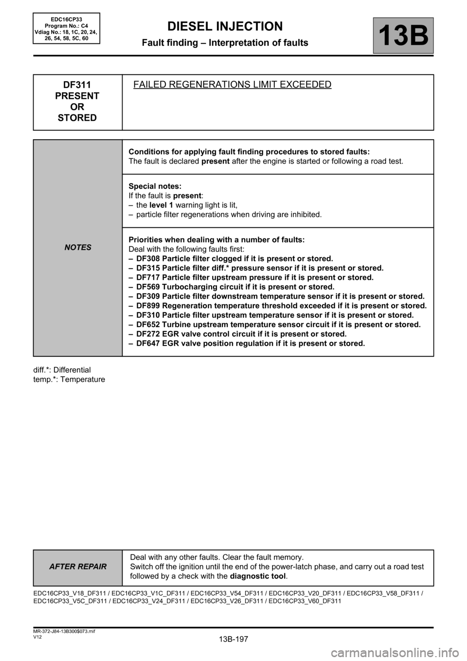
DF311
PRESENT
OR
STOREDFAILED REGENERATIONS LIMIT EXCEEDED
NOTESConditions for applying fault finding procedures to stored faults:
The fault is declared present after the engine is started or following a road test.
Special notes:
If the fault is present:
–the level 1 warning light is lit,
– particle filter regenerations when driving are inhibited.
Priorities when dealing with a number of faults:
Deal with the following faults first:
– DF308 Particle filter clogged if it is present or stored.
– DF315 Particle filter diff.* pressure sensor if it is present or stored.
– DF717 Particle filter upstream pressure if it is present or stored.
– DF569 Turbocharging circuit if it is present or stored.
– DF309 Particle filter downstream temperature sensor if it is present or stored.
– DF899 Regeneration temperature threshold exceeded if it is present or stored.
– DF310 Particle filter upstream temperature sensor if it is present or stored.
– DF652 Turbine upstream temperature sensor circuit if it is present or stored.
– DF272 EGR valve control circuit if it is present or stored.
– DF647 EGR valve position regulation if it is present or stored.
EDC16CP33_V18_DF311 / EDC16CP33_V1C_DF311 / EDC16CP33_V54_DF311 / EDC16CP33_V20_DF311 / EDC16CP33_V58_DF311 /
EDC16CP33_V5C_DF311 / EDC16CP33_V24_DF311 / EDC16CP33_V26_DF311 / EDC16CP33_V60_DF311
EDC16CP33
Program No.: C4
Vdiag No.: 18, 1C, 20, 24,
26, 54, 58, 5C, 60