wheel RENAULT SCENIC 2012 J95 / 3.G Engine And Peripherals EDC16CP33 User Guide
[x] Cancel search | Manufacturer: RENAULT, Model Year: 2012, Model line: SCENIC, Model: RENAULT SCENIC 2012 J95 / 3.GPages: 510, PDF Size: 2.98 MB
Page 314 of 510

13B-314V12 MR-372-J84-13B300$102.mif
DIESEL INJECTION
Fault finding – Interpretation of statuses13B
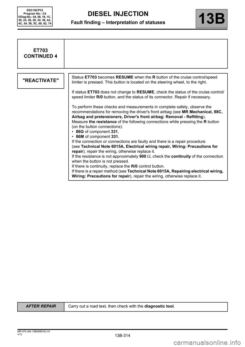
ET703
CONTINUED 4
"REACTIVATE"
Status ET703 becomes RESUME when the R button of the cruise control/speed
limiter is pressed. This button is located on the steering wheel, to the right.
If status ET703 does not change to RESUME, check the status of the cruise control/
speed limiter R/0 button, and the status of its connector. Repair if necessary.
To perform these checks and measurements in complete safety, observe the
recommendations for removing the driver's front airbag (see MR Mechanical, 88C,
Airbag and pretensioners, Driver's front airbag: Removal - Refitting).
Measure the resistance of the following connections while pressing the R button
(on the button connections):
•86G of component 331,
•86M of component 331.
If the connection or connections are faulty and there is a repair procedure
(seeTechnical Note 6015A, Electrical wiring repair, Wiring: Precautions for
repair), repair the wiring, otherwise replace it.
If the resistance is not approximately 900 Ω, check the continuity of the connection
when the button is not pressed.
If there is continuity, replace the R/0 control button.
If there is a repair method (see Technical Note 6015A, Repairing electrical wiring,
Wiring: Precautions for repair), repair the wiring, otherwise replace it.
AFTER REPAIRCarry out a road test, then check with the diagnostic tool.
EDC16CP33
Program No.: C4
VDiag No.: 04, 08, 18, 1C,
20, 24, 26, 28, 34, 38, 44,
4C, 54, 58, 5C, 60, 62, 74
Page 484 of 510

13B-484
AFTER REPAIRCarry out a road test, then check with the diagnostic tool.
V12 MR-372-J84-13B300$170.mif
DIESEL INJECTION
Fault finding – Fault Finding Chart13B
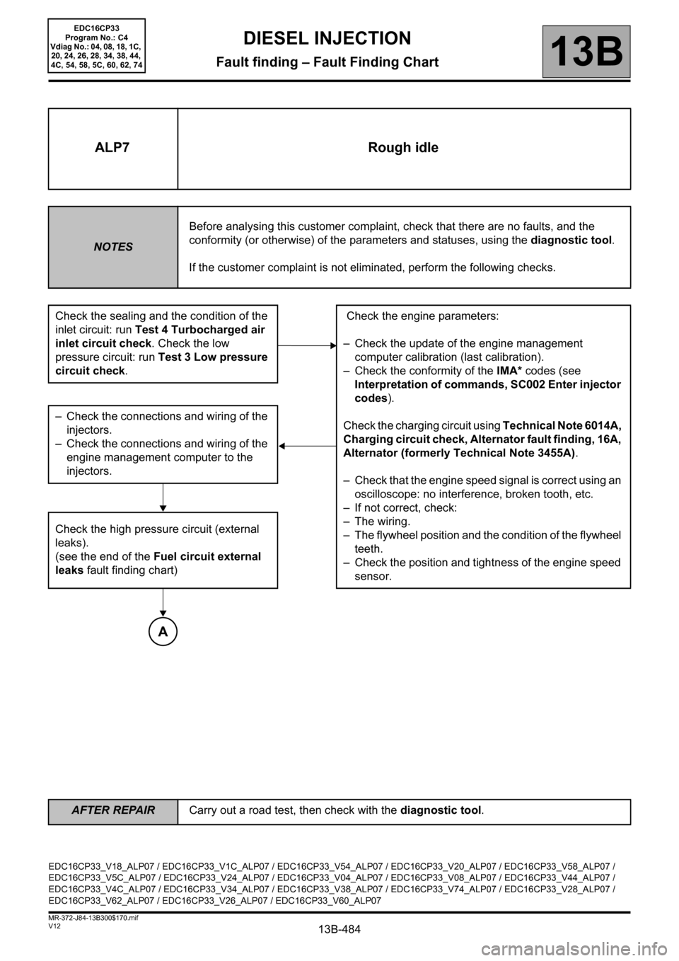
ALP7 Rough idle
NOTESBefore analysing this customer complaint, check that there are no faults, and the
conformity (or otherwise) of the parameters and statuses, using the diagnostic tool.
If the customer complaint is not eliminated, perform the following checks.
Check the sealing and the condition of the
inlet circuit: run Test 4 Turbocharged air
inlet circuit check. Check the low
pressure circuit: run Test 3 Low pressure
circuit check. Check the engine parameters:
– Check the update of the engine management
computer calibration (last calibration).
– Check the conformity of the IMA* codes (see
Interpretation of commands, SC002 Enter injector
codes).
Check the charging circuit using Technical Note 6014A,
Charging circuit check, Alternator fault finding, 16A,
Alternator (formerly Technical Note 3455A).
– Check that the engine speed signal is correct using an
oscilloscope: no interference, broken tooth, etc.
– If not correct, check:
– The wiring.
– The flywheel position and the condition of the flywheel
teeth.
– Check the position and tightness of the engine speed
sensor. – Check the connections and wiring of the
injectors.
– Check the connections and wiring of the
engine management computer to the
injectors.
Check the high pressure circuit (external
leaks).
(see the end of the Fuel circuit external
leaks fault finding chart)
A
EDC16CP33_V18_ALP07 / EDC16CP33_V1C_ALP07 / EDC16CP33_V54_ALP07 / EDC16CP33_V20_ALP07 / EDC16CP33_V58_ALP07 /
EDC16CP33_V5C_ALP07 / EDC16CP33_V24_ALP07 / EDC16CP33_V04_ALP07 / EDC16CP33_V08_ALP07 / EDC16CP33_V44_ALP07 /
EDC16CP33_V4C_ALP07 / EDC16CP33_V34_ALP07 / EDC16CP33_V38_ALP07 / EDC16CP33_V74_ALP07 / EDC16CP33_V28_ALP07 /
EDC16CP33_V62_ALP07 / EDC16CP33_V26_ALP07 / EDC16CP33_V60_ALP07
EDC16CP33
Program No.: C4
Vdiag No.: 04, 08, 18, 1C,
20, 24, 26, 28, 34, 38, 44,
4C, 54, 58, 5C, 60, 62, 74