CONNECTOR A RENAULT SCENIC 2012 J95 / 3.G Engine And Peripherals EDC16CP33 Workshop Manual
[x] Cancel search | Manufacturer: RENAULT, Model Year: 2012, Model line: SCENIC, Model: RENAULT SCENIC 2012 J95 / 3.GPages: 510, PDF Size: 2.98 MB
Page 3 of 510
13B-3V12 MR-372-J84-13B300$010.mif
DIESEL INJECTION
Fault finding – Introduction13B
EDC16CP33
Program No.: C4
Vdiag No.: 04, 08, 18, 1C,
20, 24, 26, 28, 34, 38, 44,
4C, 54, 58, 5C, 60, 62, 74
Faults
Faults are declared present or stored (depending on whether they appeared in a certain context and have
disappeared since, or whether they remain present but are not diagnosed within the current context).
The present or stored status of faults should be taken into consideration when the diagnostic tool is switched on
following + after ignition feed is activated (no system components active).
For a present fault, apply the procedure described in the Interpretation of faults section.
For a stored fault, note the faults displayed and apply the Notes section.
If the fault is confirmed when the instructions are applied, the fault is present. Deal with the fault.
If the fault is not confirmed, check:
– the electrical lines which correspond to the fault,
– the connectors on these lines (corrosion, bent pins, etc.),
– the resistance of the faulty component,
– the condition of the wires (melted or cut insulation, wear).
Conformity check
The purpose of the conformity check is to check data that does not produce a fault on the diagnostic tool if the data
is inconsistent. Therefore, this stage is used to:
– carry out fault finding on faults that do not have a fault display, and which may correspond to a customer complaint.
– check that the system is operating correctly and that there is no risk of a fault recurring after repair.
The conformity check is a fault finding procedure carried out using the interpretation of statuses and parameters.
If a status does not function normally or a parameter is outside the permitted tolerance values, consult the
corresponding fault finding pages (see interpretation of statuses and parameters).
Customer complaints - Fault finding chart
If the test with the diagnostic tool is correct but the customer complaint is still present, the fault should be dealt with
by customer complaints. WARNING:
Deal first with instrument panel faults (eg. "Particle filter" warning light).
Then carry out scheduled maintenance on the vehicle.
A synopsis of the general procedure to follow is provided on the following page in the form of a flow chart.
Page 5 of 510
13B-5V12 MR-372-J84-13B300$010.mif
DIESEL INJECTION
Fault finding – Introduction13B
EDC16CP33
Program No.: C4
Vdiag No.: 04, 08, 18, 1C,
20, 24, 26, 28, 34, 38, 44,
4C, 54, 58, 5C, 60, 62, 74
4. FAULT FINDING PROCEDURE (continued)
4.1 Wiring check
Fault finding problems
Disconnecting the connectors and/or manipulating the wiring may temporarily clear the cause of a fault.
Electrical measurements of voltage, resistance and insulation are generally correct, especially if the fault is not
present when the analysis is made (stored fault).
Visual inspection
Look for damage under the bonnet and in the passenger compartment.
Carefully check the fuses, insulators and wiring harness routing.
Look for signs of oxidation.
Physical inspection
When handling the wiring, use the diagnostic tool to detect any change in the status of the fault from stored to
present.
Make sure that the connectors are firmly secured.
Apply light pressure to the connectors.
Twist the wiring harness.
If there is a change in status, try to locate the source of the fault.
Inspection of each component
Disconnect the connectors and check the appearance of the clips and tabs, as well as the crimping (no crimping
on the insulating section).
Make sure that the clips and tabs are properly locked in the sockets.
Check that the clips or tabs have not been bent back during connection.
Check the clip contact pressure using an appropriate model of tab.
Resistance check
Check the continuity of entire lines, then section by section.
Look for a short circuit to earth, to + 12 V or with another wire.
If a fault is detected, repair or replace the wiring harness.
Page 6 of 510
13B-6V12 MR-372-J84-13B300$010.mif
DIESEL INJECTION
Fault finding – Introduction13B
EDC16CP33
Program No.: C4
Vdiag No.: 04, 08, 18, 1C,
20, 24, 26, 28, 34, 38, 44,
4C, 54, 58, 5C, 60, 62, 74
4.2 Connector check
1. Visual inspection of the connection:
– Check that the connector is connected correctly and that the male and female parts of the connection are correctly
coupled.
2. Visual inspection of the area around the connection:
– Check the condition of the mounting (pin, strap, adhesive tape, etc.) if the connectors are attached to the vehicle.
– Check that there is no damage to the wiring trim (sheath, foam, adhesive tape, etc.) near the wiring.
– Check that there is no damage to the electrical wires at the connector outputs, in particular on the insulating material
(wear, cuts, burns, etc.).
Disconnect the connector to continue the checks.
3. Visual inspection of the plastic casing:
– Check that there is no mechanical damage (casing crushed, cracked, broken, etc.), in particular to the fragile
components (lever, lock, terminal locations, etc.).
– Check that there is no heat damage (casing melted, blackened, deformed, etc.).
– Check that there are is no dirt (grease, mud, liquid, etc.).
4. visual inspection of the metal contacts:
(The female contact is called CLIP. The male contact is called TAB).
– Check that there are no bent contacts (the contact is not inserted correctly and can come out of the back of the
connector). The spring contact of the connector when the wire is pulled slightly.
– Check that there is no damage (tabs bent, clips open too wide, blackened or melted, etc.).
– Check that there is no oxidation on the metal contacts.
Visual inspection of the sealing:
(Only for watertight connectors)
– Check for the seal on the connection (between the 2 parts of the connection).
– Check the seal at the back of the connectors:
– For unit joints (1 for each wire), check that the unit joints are present on each electrical wire and that they are
correctly positioned in the opening (level with the housing). Check that plugs are present on openings which are
not used.
– For a grommet seal (one seal which covers the entire internal surface of the connector), check that the seal is
present.
– For gel seals, check for gel in all of the openings without removing the excess or any protruding sections
(it does not matter if there is gel on the contacts).
– For hotmelt sealing (heat-shrink sleeve with adhesive), check that the sleeve has shrunk correctly on the back
of the connectors and electrical wires, and that the hardened adhesive is evident from the wire ends.
– Check that there is no damage to any of the seals (cuts, burns, significant deformation, etc.).
If a fault is detected, consult Technical Note 6015A, Repairing electrical wiring. Note:
Carry out each requested check visually. Do not remove a connector if it is not required.
Note:
The check is carried out on the 2 parts of the connection. There may be 2 types of connections:
– Connector/Connector.
– Connector/Device.
Page 8 of 510
13B-8V12 MR-372-J84-13B300$020.mif
13B
EDC16CP33
Program No.: C4
Vdiag No.: 04, 08, 18, 1C,
20, 24, 26, 28, 34, 38, 44,
4C, 54, 58, 5C, 60, 62, 74
I - HAZARDS ASSOCIATED WITH CONTAMINATION
The high pressure direct injection system is highly sensitive to contamination. The risks caused by the introduction of
contamination are:
– damage to or destruction of the high pressure injection system,
– a component seizing up,
– a component losing its sealing.
All After-Sales operations must be performed under very clean conditions. This means that no impurities
(particles a few microns in size) should have penetrated the system during dismantling.
The cleanliness guidelines must be applied from the filter through to the injectors.
What are the sources of contamination?
– metal or plastic swarf,
– paint,
–fibres:
– from cardboard,
– from brushes,
– from paper,
– from clothing,
– from cloths,
– foreign bodies such as hair,
– the ambient atmosphere
–etc.
IMPORTANT:
Cleaning the engine using a high pressure washer is prohibited because of the risk of damaging connections.
In addition, moisture may collect in the connectors and create faults in the electrical connections.
DIESEL INJECTION
Fault finding – Cleanliness guidelines
Page 25 of 510
13B-25V12 MR-372-J84-13B300$050.mif
DIESEL INJECTION
Fault finding – Replacement of components13B
EDC16CP33
Program No.: C4
Vdiag No.: 04, 08, 18, 1C,
20, 24, 26, 28, 34, 38, 44,
4C, 54, 58, 5C, 60, 62, 74
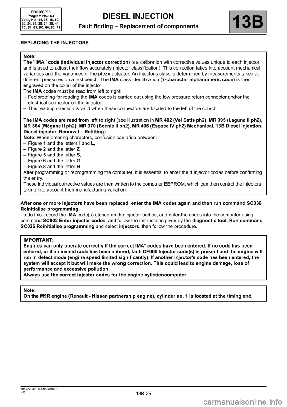
REPLACING THE INJECTORS
After one or more injectors have been replaced, enter the IMA codes again and then run command SC036
Reinitialise programming.
To do this, record the IMA code(s) etched on the injector bodies, and enter the codes into the computer using
command SC002 Enter injector codes, and follow the instructions given by the diagnostic tool. Run command
SC036 Reinitialise programming and select injectors, then follow the procedure. Note:
The "IMA" code (individual injector correction) is a calibration with corrective values unique to each injector,
and is used to adjust their flow accurately (injector classification). This correction takes into account mechanical
variances and the variances of the piezo actuator. An injector's class is determined by measurements taken at
different pressures on a test bench. The IMA class identification (7-character alphanumeric code) is then
engraved on the collar of the injector.
The IMA codes must be read from left to right:
– Foolproofing for reading the IMA codes is carried out using the low pressure return connector and/or the
electrical connector on the injector.
– This reading direction is valid when these connectors are located to the left of the cotech.
The IMA codes are read from left to right (see illustration in MR 402 (Vel Satis ph2), MR 395 (Laguna II ph2),
MR 364 (Mégane II ph2), MR 370 (Scénic II ph2), MR 405 (Espace IV ph2) Mechanical, 13B Diesel injection,
Diesel injector, Removal – Refitting)
Note: When entering characters, confusion can arise between:
– Figure 1 and the letters I and L,
– Figure 2 and the letter Z,
– Figure 5 and the letter S,
– Figure 6 and the letter G,
– Figure 8 and the letter B.
After programming or reprogramming the computer, it is essential to enter the 4 injector codes before confirming
the entry.
These individual corrective values are then written to the computer EEPROM, which can then control the injectors,
taking into account their manufacturing variation.
IMPORTANT:
Engines can only operate correctly if the correct IMA* codes have been entered. If no code has been
entered, or if an invalid code has been entered, fault DF066 Injector code(s) is present and the engine will
run in defect mode (engine speed limited significantly). If another injector's code has been entered, the
system will accept it but will make the wrong correction. This could lead to engine damage, loss of
performance and excessive pollution.
Always use the correct injector codes for the engine cylinder/computer.
Note:
On the M9R engine (Renault - Nissan partnership engine), cylinder no. 1 is located at the timing end.
Page 31 of 510
13B-31
AFTER REPAIRDeal with any other faults. Clear the fault memory.
Switch off the ignition until the end of the power-latch phase, and carry out a road test
followed by a check with the diagnostic tool.
V12 MR-372-J84-13B300$071.mif
13B
EDC16CP33
Program No.: C4
Vdiag No.: 04, 08, 18, 1C,
20, 24, 26, 28, 34, 38, 44,
4C, 54, 58, 5C, 60, 62, 74
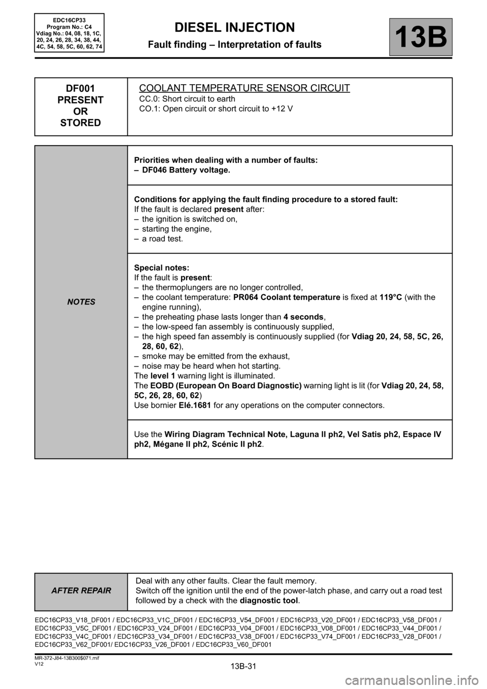
DF001
PRESENT
OR
STOREDCOOLANT TEMPERATURE SENSOR CIRCUIT
CC.0: Short circuit to earth
CO.1: Open circuit or short circuit to +12 V
NOTESPriorities when dealing with a number of faults:
– DF046 Battery voltage.
Conditions for applying the fault finding procedure to a stored fault:
If the fault is declared present after:
– the ignition is switched on,
– starting the engine,
– a road test.
Special notes:
If the fault is present:
– the thermoplungers are no longer controlled,
– the coolant temperature: PR064 Coolant temperature is fixed at 119°C (with the
engine running),
– the preheating phase lasts longer than 4 seconds,
– the low-speed fan assembly is continuously supplied,
– the high speed fan assembly is continuously supplied (for Vdiag 20, 24, 58, 5C, 26,
28, 60, 62),
– smoke may be emitted from the exhaust,
– noise may be heard when hot starting.
The level 1 warning light is illuminated.
The EOBD (European On Board Diagnostic) warning light is lit (for Vdiag 20, 24, 58,
5C, 26, 28, 60, 62)
Use bornier Elé.1681 for any operations on the computer connectors.
Use the Wiring Diagram Technical Note, Laguna II ph2, Vel Satis ph2, Espace IV
ph2, Mégane II ph2, Scénic II ph2.
EDC16CP33_V18_DF001 / EDC16CP33_V1C_DF001 / EDC16CP33_V54_DF001 / EDC16CP33_V20_DF001 / EDC16CP33_V58_DF001 /
EDC16CP33_V5C_DF001 / EDC16CP33_V24_DF001 / EDC16CP33_V04_DF001 / EDC16CP33_V08_DF001 / EDC16CP33_V44_DF001 /
EDC16CP33_V4C_DF001 / EDC16CP33_V34_DF001 / EDC16CP33_V38_DF001 / EDC16CP33_V74_DF001 / EDC16CP33_V28_DF001 /
EDC16CP33_V62_DF001/ EDC16CP33_V26_DF001 / EDC16CP33_V60_DF001
DIESEL INJECTION
Fault finding – Interpretation of faults
Page 32 of 510
13B-32
AFTER REPAIRDeal with any other faults. Clear the fault memory.
Switch off the ignition until the end of the power-latch phase, and carry out a road test
followed by a check with the diagnostic tool.
V12 MR-372-J84-13B300$071.mif
DIESEL INJECTION
Fault finding – Interpretation of faults13B
EDC16CP33
Program No.: C4
Vdiag No.: 04, 08, 18, 1C,
20, 24, 26, 28, 34, 38, 44,
4C, 54, 58, 5C, 60, 62, 74
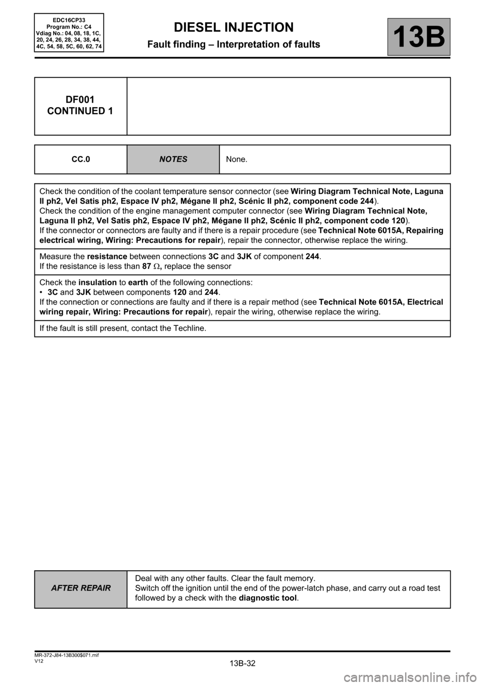
DF001
CONTINUED 1
CC.0NOTESNone.
Check the condition of the coolant temperature sensor connector (see Wiring Diagram Technical Note, Laguna
II ph2, Vel Satis ph2, Espace IV ph2, Mégane II ph2, Scénic II ph2, component code 244).
Check the condition of the engine management computer connector (see Wiring Diagram Technical Note,
Laguna II ph2, Vel Satis ph2, Espace IV ph2, Mégane II ph2, Scénic II ph2, component code 120).
If the connector or connectors are faulty and if there is a repair procedure (see Technical Note 6015A, Repairing
electrical wiring, Wiring: Precautions for repair), repair the connector, otherwise replace the wiring.
Measure the resistance between connections 3C and 3JK of component 244.
If the resistance is less than 87 Ω, replace the sensor
Check the insulation to earth of the following connections:
•3C and 3JK between components 120 and 244.
If the connection or connections are faulty and if there is a repair method (see Technical Note 6015A, Electrical
wiring repair, Wiring: Precautions for repair), repair the wiring, otherwise replace the wiring.
If the fault is still present, contact the Techline.
Page 33 of 510
13B-33
AFTER REPAIRDeal with any other faults. Clear the fault memory.
Switch off the ignition until the end of the power-latch phase, and carry out a road test
followed by a check with the diagnostic tool.
V12 MR-372-J84-13B300$071.mif
DIESEL INJECTION
Fault finding – Interpretation of faults13B
EDC16CP33
Program No.: C4
Vdiag No.: 04, 08, 18, 1C,
20, 24, 26, 28, 34, 38, 44,
4C, 54, 58, 5C, 60, 62, 74
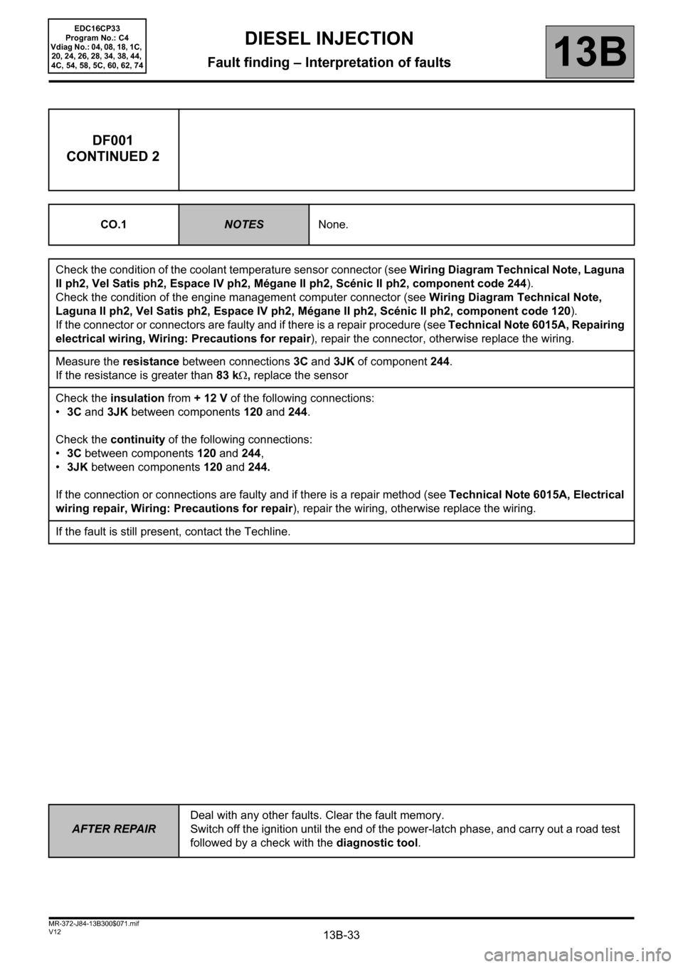
DF001
CONTINUED 2
CO.1NOTESNone.
Check the condition of the coolant temperature sensor connector (see Wiring Diagram Technical Note, Laguna
II ph2, Vel Satis ph2, Espace IV ph2, Mégane II ph2, Scénic II ph2, component code 244).
Check the condition of the engine management computer connector (see Wiring Diagram Technical Note,
Laguna II ph2, Vel Satis ph2, Espace IV ph2, Mégane II ph2, Scénic II ph2, component code 120).
If the connector or connectors are faulty and if there is a repair procedure (see Technical Note 6015A, Repairing
electrical wiring, Wiring: Precautions for repair), repair the connector, otherwise replace the wiring.
Measure the resistance between connections 3C and 3JK of component 244.
If the resistance is greater than 83 kΩ, replace the sensor
Check the insulation from + 12 V of the following connections:
•3C and 3JK between components 120 and 244.
Check the continuity of the following connections:
•3C between components 120 and 244,
•3JK between components 120 and 244.
If the connection or connections are faulty and if there is a repair method (see Technical Note 6015A, Electrical
wiring repair, Wiring: Precautions for repair), repair the wiring, otherwise replace the wiring.
If the fault is still present, contact the Techline.
Page 34 of 510
13B-34
AFTER REPAIRDeal with any other faults. Clear the fault memory.
Switch off the ignition until the end of the power-latch phase, and carry out a road test
followed by a check with the diagnostic tool.
V12 MR-372-J84-13B300$071.mif
DIESEL INJECTION
Fault finding – Interpretation of faults13B
EDC16CP33
Program No.: C4
Vdiag No.: 04, 08, 18, 1C,
20, 24, 26, 28, 34, 38, 44,
4C, 54, 58, 5C, 60, 62, 74
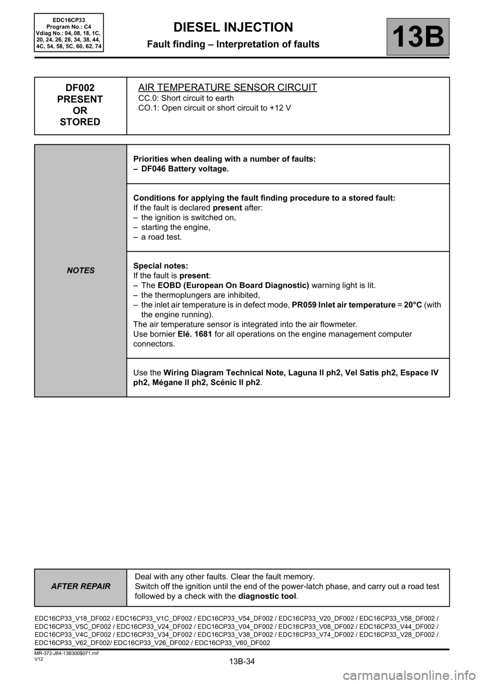
DF002
PRESENT
OR
STOREDAIR TEMPERATURE SENSOR CIRCUIT
CC.0: Short circuit to earth
CO.1: Open circuit or short circuit to +12 V
NOTESPriorities when dealing with a number of faults:
– DF046 Battery voltage.
Conditions for applying the fault finding procedure to a stored fault:
If the fault is declared present after:
– the ignition is switched on,
– starting the engine,
– a road test.
Special notes:
If the fault is present:
–The EOBD (European On Board Diagnostic) warning light is lit.
– the thermoplungers are inhibited,
– the inlet air temperature is in defect mode, PR059 Inlet air temperature = 20°C (with
the engine running).
The air temperature sensor is integrated into the air flowmeter.
Use bornier Elé. 1681 for all operations on the engine management computer
connectors.
Use the Wiring Diagram Technical Note, Laguna II ph2, Vel Satis ph2, Espace IV
ph2, Mégane II ph2, Scénic II ph2.
EDC16CP33_V18_DF002 / EDC16CP33_V1C_DF002 / EDC16CP33_V54_DF002 / EDC16CP33_V20_DF002 / EDC16CP33_V58_DF002 /
EDC16CP33_V5C_DF002 / EDC16CP33_V24_DF002 / EDC16CP33_V04_DF002 / EDC16CP33_V08_DF002 / EDC16CP33_V44_DF002 /
EDC16CP33_V4C_DF002 / EDC16CP33_V34_DF002 / EDC16CP33_V38_DF002 / EDC16CP33_V74_DF002 / EDC16CP33_V28_DF002 /
EDC16CP33_V62_DF002/ EDC16CP33_V26_DF002 / EDC16CP33_V60_DF002
Page 35 of 510
13B-35
AFTER REPAIRDeal with any other faults. Clear the fault memory.
Switch off the ignition until the end of the power-latch phase, and carry out a road test
followed by a check with the diagnostic tool.
V12 MR-372-J84-13B300$071.mif
DIESEL INJECTION
Fault finding – Interpretation of faults13B
EDC16CP33
Program No.: C4
Vdiag No.: 04, 08, 18, 1C,
20, 24, 26, 28, 34, 38, 44,
4C, 54, 58, 5C, 60, 62, 74
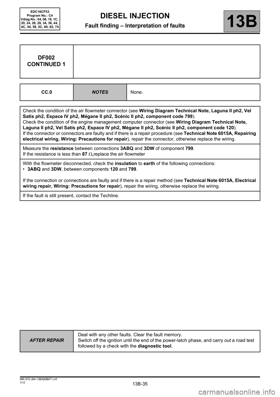
DF002
CONTINUED 1
CC.0NOTESNone.
Check the condition of the air flowmeter connector (see Wiring Diagram Technical Note, Laguna II ph2, Vel
Satis ph2, Espace IV ph2, Mégane II ph2, Scénic II ph2, component code 799).
Check the condition of the engine management computer connector (see Wiring Diagram Technical Note,
Laguna II ph2, Vel Satis ph2, Espace IV ph2, Mégane II ph2, Scénic II ph2, component code 120).
If the connector or connectors are faulty and if there is a repair procedure (see Technical Note 6015A, Repairing
electrical wiring, Wiring: Precautions for repair), repair the connector, otherwise replace the wiring.
Measure the resistance between connections 3ABQ and 3DW of component 799.
If the resistance is less than 87 Ω,replace the air flowmeter
With the flowmeter disconnected, check the insulation to earth of the following connections:
•3ABQ and 3DW, between components 120 and 799.
If the connection or connections are faulty and if there is a repair method (see Technical Note 6015A, Electrical
wiring repair, Wiring: Precautions for repair), repair the wiring, otherwise replace the wiring.
If the fault is still present, contact the Techline.