PR041 RENAULT SCENIC 2012 J95 / 3.G Engine And Peripherals EDC16CP33 Workshop Manual
[x] Cancel search | Manufacturer: RENAULT, Model Year: 2012, Model line: SCENIC, Model: RENAULT SCENIC 2012 J95 / 3.GPages: 510, PDF Size: 2.98 MB
Page 37 of 510
13B-37
AFTER REPAIRDeal with any other faults. Clear the fault memory.
Switch off the ignition until the end of the power-latch phase, and carry out a road test
followed by a check with the diagnostic tool.
V12 MR-372-J84-13B300$071.mif
DIESEL INJECTION
Fault finding – Interpretation of faults13B
EDC16CP33
Program No.: C4
Vdiag No.: 04, 08, 18, 1C,
20, 24, 26, 28, 34, 38, 44,
4C, 54, 58, 5C, 60, 62, 74
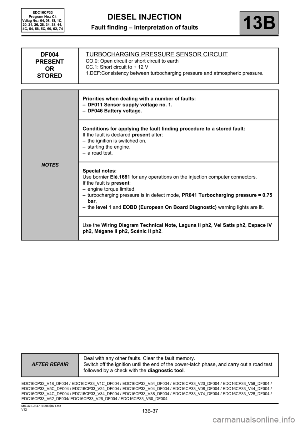
DF004
PRESENT
OR
STOREDTURBOCHARGING PRESSURE SENSOR CIRCUIT
CO.0: Open circuit or short circuit to earth
CC.1: Short circuit to + 12 V
1.DEF:Consistency between turbocharging pressure and atmospheric pressure.
NOTESPriorities when dealing with a number of faults:
– DF011 Sensor supply voltage no. 1.
– DF046 Battery voltage.
Conditions for applying the fault finding procedure to a stored fault:
If the fault is declared present after:
– the ignition is switched on,
– starting the engine,
– a road test.
Special notes:
Use bornier Elé.1681 for any operations on the injection computer connectors.
If the fault is present:
– engine torque limited,
– turbocharging pressure is in defect mode, PR041 Turbocharging pressure = 0.75
bar,
–the level 1 and EOBD (European On Board Diagnostic) warning lights are lit.
Use the Wiring Diagram Technical Note, Laguna II ph2, Vel Satis ph2, Espace IV
ph2, Mégane II ph2, Scénic II ph2.
EDC16CP33_V18_DF004 / EDC16CP33_V1C_DF004 / EDC16CP33_V54_DF004 / EDC16CP33_V20_DF004 / EDC16CP33_V58_DF004 /
EDC16CP33_V5C_DF004 / EDC16CP33_V24_DF004 / EDC16CP33_V04_DF004 / EDC16CP33_V08_DF004 / EDC16CP33_V44_DF004 /
EDC16CP33_V4C_DF004 / EDC16CP33_V34_DF004 / EDC16CP33_V38_DF004 / EDC16CP33_V74_DF004 / EDC16CP33_V28_DF004 /
EDC16CP33_V62_DF004/ EDC16CP33_V26_DF004 / EDC16CP33_V60_DF004
Page 39 of 510

13B-39
AFTER REPAIRDeal with any other faults. Clear the fault memory.
Switch off the ignition until the end of the power-latch phase, and carry out a road test
followed by a check with the diagnostic tool.
V12 MR-372-J84-13B300$071.mif
DIESEL INJECTION
Fault finding – Interpretation of faults13B
EDC16CP33
Program No.: C4
Vdiag No.: 04, 08, 18, 1C,
20, 24, 26, 28, 34, 38, 44,
4C, 54, 58, 5C, 60, 62, 74
DF004
CONTINUED 2
CC.1NOTESNone.
Check the condition of the turbocharging pressure sensor connector (see Wiring Diagram Technical Note,
Laguna II ph2, Vel Satis ph2, Espace IV ph2, Mégane II ph2, Scénic II ph2, component code 1071).
Check the condition of the engine management computer connector (see Wiring Diagram Technical Note,
Laguna II ph2, Vel Satis ph2, Espace IV ph2, Mégane II ph2, Scénic II ph2, component code 120).
If the connector or connectors are faulty and if there is a repair procedure (see Technical Note 6015A, Repairing
electrical wiring, Wiring: Precautions for repair), repair the connector, otherwise replace the wiring.
Check the insulation in relation to + 12 V or + 5 V (computer feed) of the following connections:
•3LP and 3LQ, between components 120 and 1071.
Check the continuity of the following connection:
•3LN between components 120 and 1071.
If the connection or connections are faulty and if there is a repair method (see Technical Note 6015A, Electrical
wiring repair, Wiring: Precautions for repair), repair the wiring, otherwise replace the wiring.
Run Test 8 Turbocharger rotating part.
If the fault is still present, replace the turbocharging pressure sensor.
1.DEF
NOTESNone.
Check the condition of the turbocharging pressure sensor connector (see Wiring Diagram Technical Note,
Laguna II ph2, Vel Satis ph2, Espace IV ph2, Mégane II ph2, Scénic II ph2, component code 1071).
Check the condition of the engine management computer connector (see Wiring Diagram Technical Note,
Laguna II ph2, Vel Satis ph2, Espace IV ph2, Mégane II ph2, Scénic II ph2, component code 120).
If the connector or connectors are faulty and if there is a repair procedure (see Technical Note 6015A, Repairing
electrical wiring, Wiring: Precautions for repair), repair the connector, otherwise replace the wiring.
Perform fault finding procedure on parameter PR041 Turbocharging pressure.
Page 220 of 510
13B-220
AFTER REPAIRDeal with any other faults. Clear the fault memory.
Switch off the ignition until the end of the power-latch phase, and carry out a road test
followed by a check with the diagnostic tool.
V12 MR-372-J84-13B300$074.mif
DIESEL INJECTION
Fault finding – Interpretation of faults13B
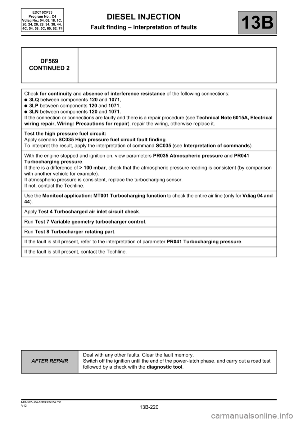
DF569
CONTINUED 2
Check for continuity and absence of interference resistance of the following connections:
●3LQ between components 120 and 1071,
●3LP between components 120 and 1071,
●3LN between components 120 and 1071.
If the connection or connections are faulty and there is a repair procedure (see Technical Note 6015A, Electrical
wiring repair, Wiring: Precautions for repair), repair the wiring, otherwise replace it.
Test the high pressure fuel circuit:
Apply scenario SC035 High pressure fuel circuit fault finding.
To interpret the result, apply the interpretation of command SC035 (see Interpretation of commands).
With the engine stopped and ignition on, view parameters PR035 Atmospheric pressure and PR041
Turbocharging pressure.
If there is a difference of > 100 mbar, check that the atmospheric pressure reading is consistent (by comparison
with another vehicle for example).
If atmospheric pressure is consistent, replace the turbocharging sensor.
If not, contact the Techline.
Use the Monitool application: MT001 Turbocharging function to check the entire air line (only for Vdiag 04 and
44).
Apply Test 4 Turbocharged air inlet circuit check.
Run Test 7 Variable geometry turbocharger control.
Run Test 8 Turbocharger rotating part.
If the fault is still present, refer to the interpretation of parameter PR041 Turbocharging pressure.
If the fault is still present, contact the Techline.
EDC16CP33
Program No.: C4
Vdiag No.: 04, 08, 18, 1C,
20, 24, 26, 28, 34, 38, 44,
4C, 54, 58, 5C, 60, 62, 74
Page 325 of 510
13B-325V12 MR-372-J84-13B300$110.mif
13B
EDC16CP33
Program No.: C4
VDiag No.: 04, 08, 18, 1C,
20, 24, 26, 28, 34, 38, 44,
4C, 54, 58, 5C, 60, 62, 74
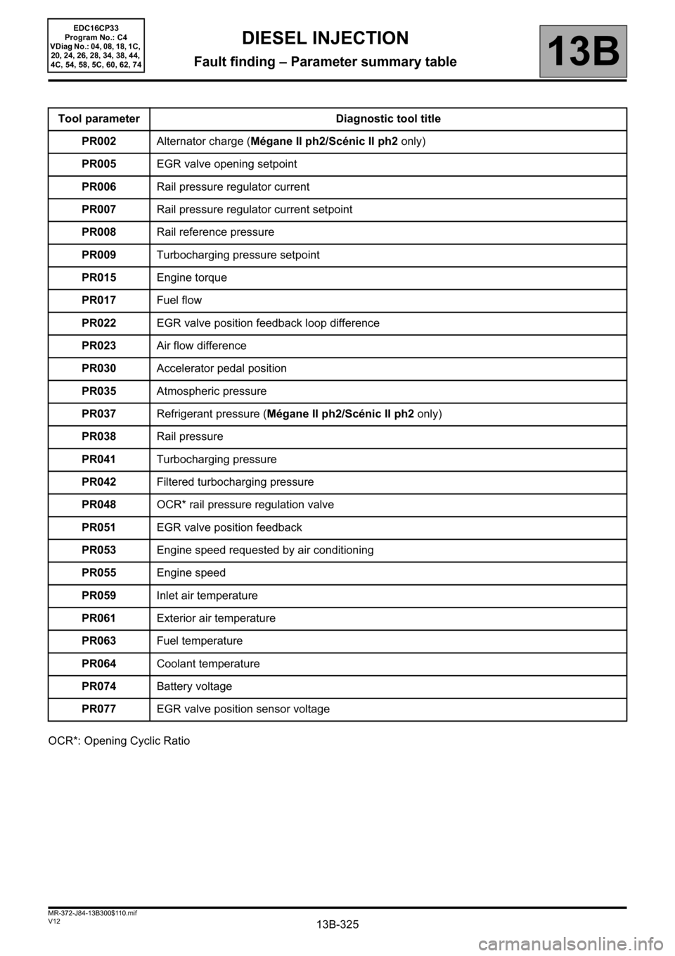
OCR*: Opening Cyclic RatioTool parameter Diagnostic tool title
PR002Alternator charge (Mégane II ph2/Scénic II ph2 only)
PR005EGR valve opening setpoint
PR006Rail pressure regulator current
PR007Rail pressure regulator current setpoint
PR008Rail reference pressure
PR009Turbocharging pressure setpoint
PR015Engine torque
PR017Fuel flow
PR022EGR valve position feedback loop difference
PR023Air flow difference
PR030Accelerator pedal position
PR035Atmospheric pressure
PR037Refrigerant pressure (Mégane II ph2/Scénic II ph2 only)
PR038Rail pressure
PR041Turbocharging pressure
PR042Filtered turbocharging pressure
PR048OCR* rail pressure regulation valve
PR051EGR valve position feedback
PR053Engine speed requested by air conditioning
PR055Engine speed
PR059Inlet air temperature
PR061Exterior air temperature
PR063Fuel temperature
PR064Coolant temperature
PR074Battery voltage
PR077EGR valve position sensor voltage
DIESEL INJECTION
Fault finding – Parameter summary table
Page 346 of 510

13B-346
AFTER REPAIRCarry out a road test, then check with the diagnostic tool.
V12 MR-372-J84-13B300$121.mif
DIESEL INJECTION
Fault finding – Interpretation of parameters13B
PR041TURBOCHARGING PRESSURE
PARAMETER
DEFINITIONThis parameter indicates the turbocharging pressure in bar.
NOTESNone.
Conformity check with engine stopped and ignition on, or engine running, and engine coolant
temperature > 80°C
The turbocharging pressure value must be:
PR041 = PR035 Atmospheric pressure + /- 0.20 bar.
In the event of a fault, consult the interpretation of DF004 Turbocharging pressure sensor circuit.
EDC16CP33_V18_PR041 / EDC16CP33_V1C_PR041 / EDC16CP33_V54_PR041 / EDC16CP33_V20_PR041 / EDC16CP33_V58_PR041 /
EDC16CP33_V5C_PR041 / EDC16CP33_V24_PR041 / EDC16CP33_V04_PR041 / EDC16CP33_V08_PR041 / EDC16CP33_V44_PR041 /
EDC16CP33_V4C_PR041 / EDC16CP33_V34_PR041 / EDC16CP33_V38_PR041 / EDC16CP33_V74_PR041 / EDC16CP33_V28_PR041 /
EDC16CP33_V62_PR041 / EDC16CP33_V26_PR041 / EDC16CP33_V60_PR041
EDC16CP33
Program No.: C4
VDiag No.: 04, 08, 18, 1C,
20, 24, 26, 28, 34, 38, 44,
4C, 54, 58, 5C, 60, 62, 74
Page 347 of 510
13B-347
AFTER REPAIRCarry out a road test, then check with the diagnostic tool.
V12 MR-372-J84-13B300$121.mif
DIESEL INJECTION
Fault finding – Interpretation of parameters13B
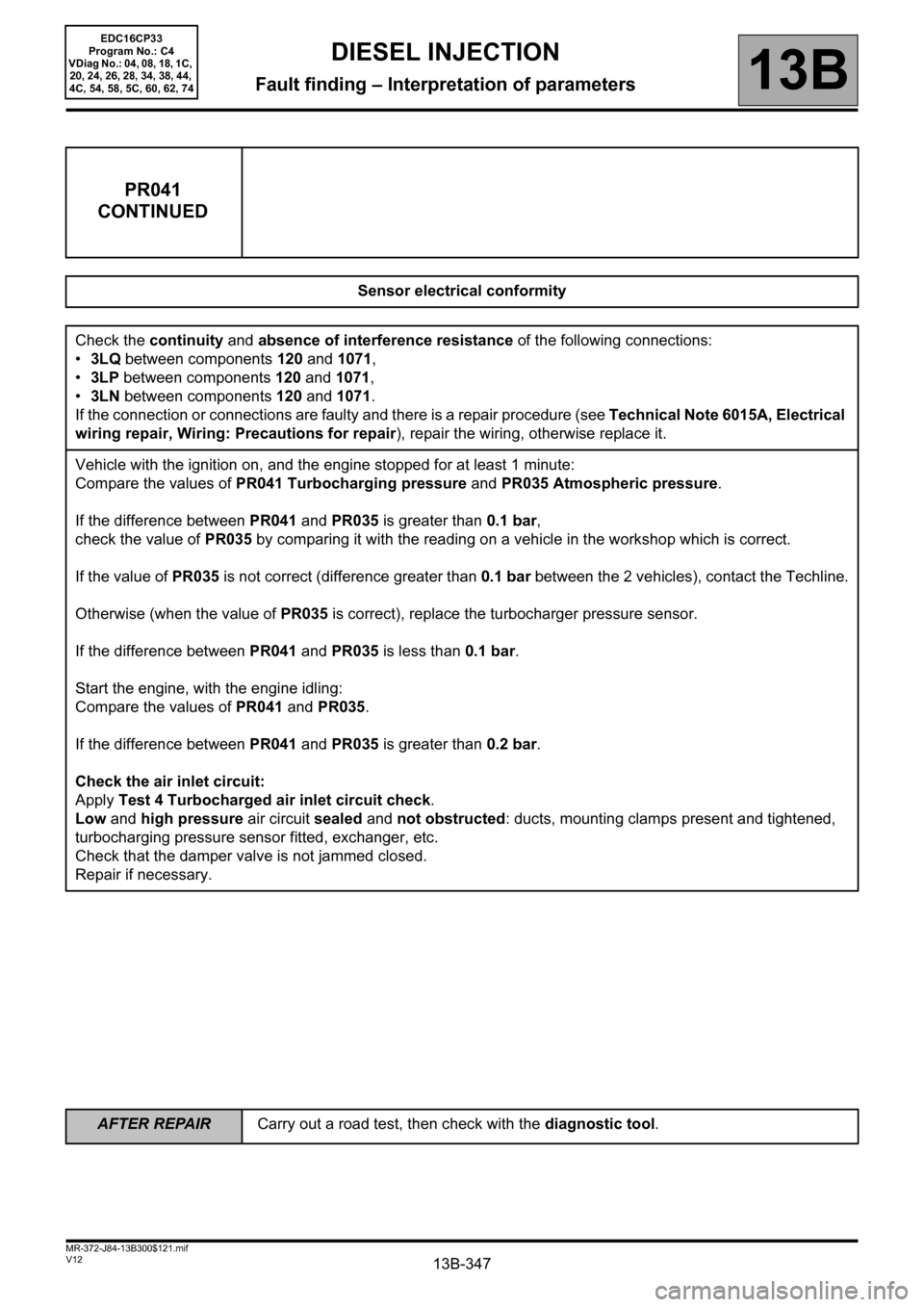
PR041
CONTINUED
Sensor electrical conformity
Check the continuity and absence of interference resistance of the following connections:
•3LQ between components 120 and 1071,
•3LP between components 120 and 1071,
•3LN between components 120 and 1071.
If the connection or connections are faulty and there is a repair procedure (see Technical Note 6015A, Electrical
wiring repair, Wiring: Precautions for repair), repair the wiring, otherwise replace it.
Vehicle with the ignition on, and the engine stopped for at least 1 minute:
Compare the values of PR041 Turbocharging pressure and PR035 Atmospheric pressure.
If the difference between PR041 and PR035 is greater than 0.1 bar,
check the value of PR035 by comparing it with the reading on a vehicle in the workshop which is correct.
If the value of PR035 is not correct (difference greater than 0.1 bar between the 2 vehicles), contact the Techline.
Otherwise (when the value of PR035 is correct), replace the turbocharger pressure sensor.
If the difference between PR041 and PR035 is less than 0.1 bar.
Start the engine, with the engine idling:
Compare the values of PR041 and PR035.
If the difference between PR041 and PR035 is greater than 0.2 bar.
Check the air inlet circuit:
Apply Test 4 Turbocharged air inlet circuit check.
Low and high pressure air circuit sealed and not obstructed: ducts, mounting clamps present and tightened,
turbocharging pressure sensor fitted, exchanger, etc.
Check that the damper valve is not jammed closed.
Repair if necessary.
EDC16CP33
Program No.: C4
VDiag No.: 04, 08, 18, 1C,
20, 24, 26, 28, 34, 38, 44,
4C, 54, 58, 5C, 60, 62, 74
Page 348 of 510

13B-348
AFTER REPAIRCarry out a road test, then check with the diagnostic tool.
V12 MR-372-J84-13B300$121.mif
DIESEL INJECTION
Fault finding – Interpretation of parameters13B
PR042FILTERED TURBOCHARGING PRESSURE
PARAMETER
DEFINITIONThis parameter indicates the filtered turbocharging pressure in bar.
NOTESNone.
Conformity check with engine stopped and ignition on, or engine running, and engine coolant
temperature > 80°C
PR042 corresponds to the average value of PR041 Turbocharging pressure.
EDC16CP33_V18_PR042 / EDC16CP33_V1C_PR042 / EDC16CP33_V54_PR042 / EDC16CP33_V20_PR042 / EDC16CP33_V58_PR042 /
EDC16CP33_V5C_PR042 / EDC16CP33_V24_PR042 / EDC16CP33_V04_PR042 / EDC16CP33_V08_PR042 / EDC16CP33_V44_PR042 /
EDC16CP33_V4C_PR042 / EDC16CP33_V34_PR042 / EDC16CP33_V38_PR042 / EDC16CP33_V74_PR042 / EDC16CP33_V28_PR042 /
EDC16CP33_V62_PR042 / EDC16CP33_V26_PR042 / EDC16CP33_V60_PR042
EDC16CP33
Program No.: C4
VDiag No.: 04, 08, 18, 1C,
20, 24, 26, 28, 34, 38, 44,
4C, 54, 58, 5C, 60, 62, 74
Page 379 of 510

13B-379V12 MR-372-J84-13B300$122.mif
DIESEL INJECTION
Fault finding – Interpretation of parameters13B
PR209TURBOCHARGING PRESSURE LOOP DIFFERENCE
PARAMETER
DEFINITIONThis parameter indicates the turbocharging pressure loop difference in bar.
NOTESNone.
Conformity check: Engine running, engine coolant temperature > 80°C, without electrical consumers.
The turbocharging pressure loop difference value must be:
PR209 = PR009 Turbocharging pressure setpoint - PR041 Turbocharging pressure = ~ 0.
If PR209 is significant, refer to the interpretation of the command AC004 Turbocharging solenoid valve.
EDC16CP33_V18_PR209 / EDC16CP33_V1C_PR209 / EDC16CP33_V54_PR209 / EDC16CP33_V20_PR209 / EDC16CP33_V58_PR209 /
EDC16CP33_V5C_PR209 / EDC16CP33_V24_PR209 / EDC16CP33_V04_PR209 / EDC16CP33_V08_PR209 / EDC16CP33_V44_PR209 /
EDC16CP33_V4C_PR209 / EDC16CP33_V34_PR209 / EDC16CP33_V38_PR209 / EDC16CP33_V74_PR209 / EDC16CP33_V28_PR209 /
EDC16CP33_V62_PR209 / EDC16CP33_V26_PR209 / EDC16CP33_V60_PR209
EDC16CP33
Program No.: C4
Vdiag No.: 04, 08, 18, 1C,
20, 24, 26, 28, 34, 38, 44,
4C, 54, 58, 5C, 60, 62, 74
AFTER REPAIRCarry out a road test, then check with the diagnostic tool.
Page 439 of 510
13B-439V12 MR-372-J84-13B300$150.mif
DIESEL INJECTION
Fault finding – Interpretation of commands13B
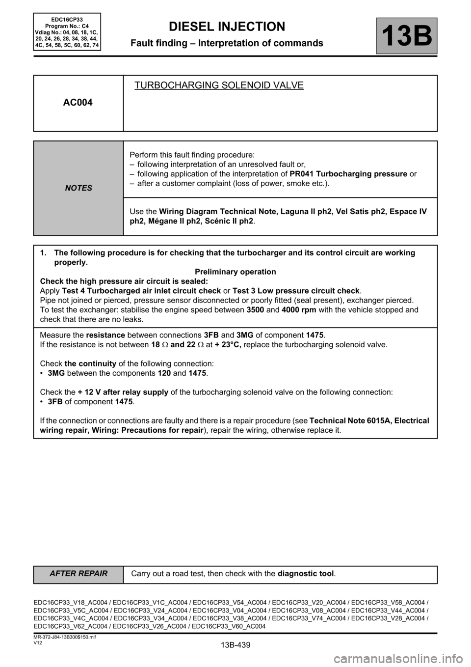
AC004TURBOCHARGING SOLENOID VALVE
NOTESPerform this fault finding procedure:
– following interpretation of an unresolved fault or,
– following application of the interpretation of PR041 Turbocharging pressure or
– after a customer complaint (loss of power, smoke etc.).
Use the Wiring Diagram Technical Note, Laguna II ph2, Vel Satis ph2, Espace IV
ph2, Mégane II ph2, Scénic II ph2.
1. The following procedure is for checking that the turbocharger and its control circuit are working
properly.
Preliminary operation
Check the high pressure air circuit is sealed:
Apply Test 4 Turbocharged air inlet circuit check or Test 3 Low pressure circuit check.
Pipe not joined or pierced, pressure sensor disconnected or poorly fitted (seal present), exchanger pierced.
To test the exchanger: stabilise the engine speed between 3500 and 4000 rpm with the vehicle stopped and
check that there are no leaks.
Measure the resistance between connections3FB and 3MG of component1475.
If the resistance is not between 18 Ω and 22 Ω at + 23°C, replace the turbocharging solenoid valve.
Check the continuity of the following connection:
•3MG between the components 120 and 1475.
Check the + 12 V after relay supply of the turbocharging solenoid valve on the following connection:
•3FB of component 1475.
If the connection or connections are faulty and there is a repair procedure (see Technical Note 6015A, Electrical
wiring repair, Wiring: Precautions for repair), repair the wiring, otherwise replace it.
EDC16CP33_V18_AC004 / EDC16CP33_V1C_AC004 / EDC16CP33_V54_AC004 / EDC16CP33_V20_AC004 / EDC16CP33_V58_AC004 /
EDC16CP33_V5C_AC004 / EDC16CP33_V24_AC004 / EDC16CP33_V04_AC004 / EDC16CP33_V08_AC004 / EDC16CP33_V44_AC004 /
EDC16CP33_V4C_AC004 / EDC16CP33_V34_AC004 / EDC16CP33_V38_AC004 / EDC16CP33_V74_AC004 / EDC16CP33_V28_AC004 /
EDC16CP33_V62_AC004 / EDC16CP33_V26_AC004 / EDC16CP33_V60_AC004
EDC16CP33
Program No.: C4
Vdiag No.: 04, 08, 18, 1C,
20, 24, 26, 28, 34, 38, 44,
4C, 54, 58, 5C, 60, 62, 74
AFTER REPAIRCarry out a road test, then check with the diagnostic tool.
Page 459 of 510
13B-459V12 MR-372-J84-13B300$150.mif
DIESEL INJECTION
Fault finding – Interpretation of commands13B
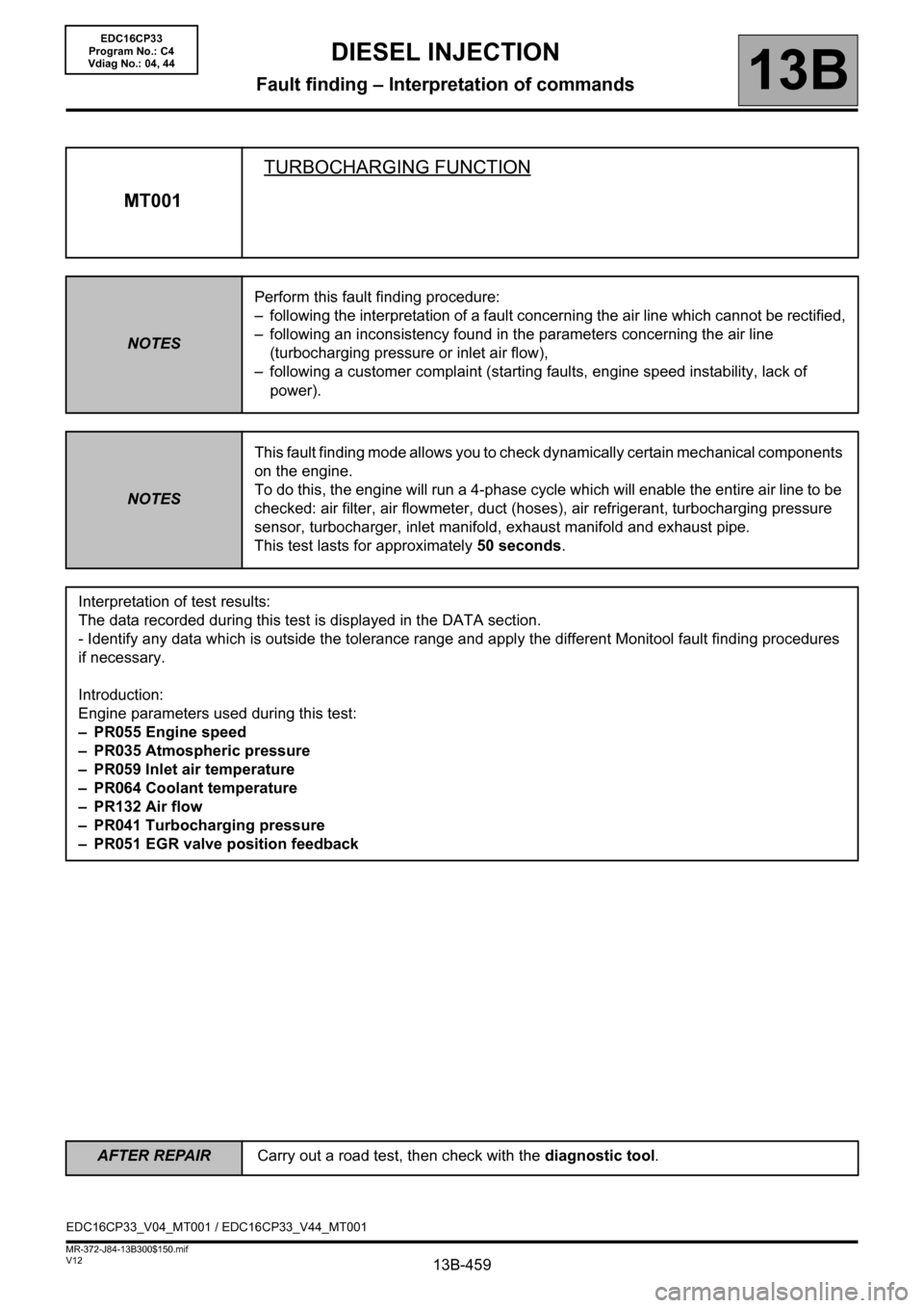
MT001TURBOCHARGING FUNCTION
NOTESPerform this fault finding procedure:
– following the interpretation of a fault concerning the air line which cannot be rectified,
– following an inconsistency found in the parameters concerning the air line
(turbocharging pressure or inlet air flow),
– following a customer complaint (starting faults, engine speed instability, lack of
power).
NOTESThis fault finding mode allows you to check dynamically certain mechanical components
on the engine.
To do this, the engine will run a 4-phase cycle which will enable the entire air line to be
checked: air filter, air flowmeter, duct (hoses), air refrigerant, turbocharging pressure
sensor, turbocharger, inlet manifold, exhaust manifold and exhaust pipe.
This test lasts for approximately 50 seconds.
Interpretation of test results:
The data recorded during this test is displayed in the DATA section.
- Identify any data which is outside the tolerance range and apply the different Monitool fault finding procedures
if necessary.
Introduction:
Engine parameters used during this test:
– PR055 Engine speed
– PR035 Atmospheric pressure
– PR059 Inlet air temperature
– PR064 Coolant temperature
–PR132 Air flow
– PR041 Turbocharging pressure
– PR051 EGR valve position feedback
EDC16CP33_V04_MT001 / EDC16CP33_V44_MT001
EDC16CP33
Program No.: C4
Vdiag No.: 04, 44
AFTER REPAIRCarry out a road test, then check with the diagnostic tool.