SC036 RENAULT SCENIC 2012 J95 / 3.G Engine And Peripherals EDC16CP33 Workshop Manual
[x] Cancel search | Manufacturer: RENAULT, Model Year: 2012, Model line: SCENIC, Model: RENAULT SCENIC 2012 J95 / 3.GPages: 510, PDF Size: 2.98 MB
Page 18 of 510
13B-18V12 MR-372-J84-13B300$030.mif
DIESEL INJECTION
Fault finding – System operation13B
EDC16CP33
Program No.: C4
Vdiag No.: 04, 08, 18, 1C,
20, 24, 26, 28, 34, 38, 44,
4C, 54, 58, 5C, 60, 62, 74
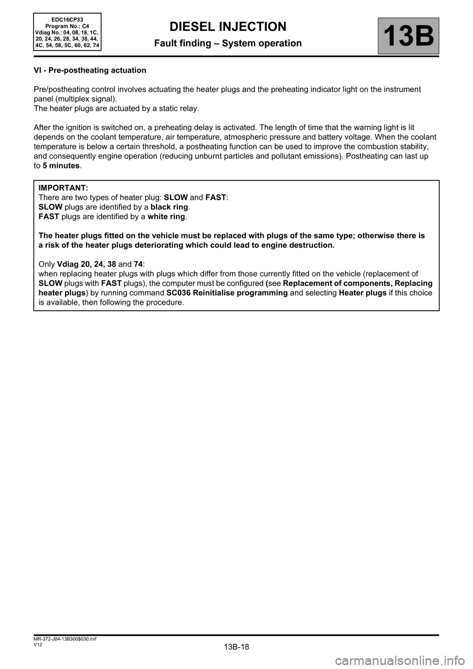
VI - Pre-postheating actuation
Pre/postheating control involves actuating the heater plugs and the preheating indicator light on the instrument
panel (multiplex signal).
The heater plugs are actuated by a static relay.
After the ignition is switched on, a preheating delay is activated. The length of time that the warning light is lit
depends on the coolant temperature, air temperature, atmospheric pressure and battery voltage. When the coolant
temperature is below a certain threshold, a postheating function can be used to improve the combustion stability,
and consequently engine operation (reducing unburnt particles and pollutant emissions). Postheating can last up
to5 minutes.
IMPORTANT:
There are two types of heater plug: SLOW and FAST:
SLOW plugs are identified by a black ring.
FAST plugs are identified by a white ring.
The heater plugs fitted on the vehicle must be replaced with plugs of the same type; otherwise there is
a risk of the heater plugs deteriorating which could lead to engine destruction.
Only Vdiag 20, 24, 38 and 74:
when replacing heater plugs with plugs which differ from those currently fitted on the vehicle (replacement of
SLOW plugs with FAST plugs), the computer must be configured (see Replacement of components, Replacing
heater plugs) by running command SC036 Reinitialise programming and selecting Heater plugs if this choice
is available, then following the procedure.
Page 22 of 510
13B-22V12 MR-372-J84-13B300$050.mif
13B
EDC16CP33
Program No.: C4
Vdiag No.: 04, 08, 18, 1C,
20, 24, 26, 28, 34, 38, 44,
4C, 54, 58, 5C, 60, 62, 74
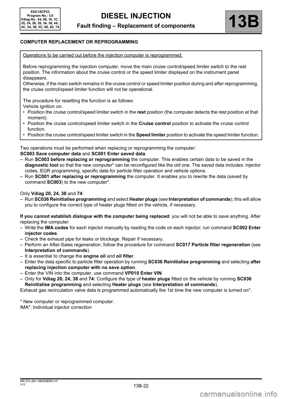
COMPUTER REPLACEMENT OR REPROGRAMMING
Two operations must be performed when replacing or reprogramming the computer:
SC003 Save computer data and SC001 Enter saved data.
–Run SC003 before replacing or reprogramming the computer. This enables certain data to be saved in the
diagnostic tool so that the new computer* can be reconfigured like the old one. The saved data includes: injector
codes, EGR programming, specific data for particle filter operation and vehicle options.
–Run SC001 after replacing or reprogramming the computer. It enables you to rewrite the data (saved by
command SC003) to the new computer*.
Only Vdiag 20, 24, 38 and 74:
–Run SC036 Reinitialise programming and select Heater plugs (see Interpretation of commands); this will allow
you to configure the correct type of heater plugs fitted on the vehicle, if necessary.
If you cannot establish dialogue with the computer being replaced: you will not be able to save anything. After
replacing the computer:
– Write the IMA codes for each injector manually by reading the code on each injector; run command SC002 Enter
injector codes.
– Check the exhaust pipe for leaks or blockage. Repair if necessary.
– Perform an After-Sales regeneration, follow the procedure for command SC017 Particle filter regeneration (see
Interpretation of commands).
– It is essential to change the engine oil and oil filter.
– Enter the data specific to particle filter operation by running SC036 Reinitialise programming and selecting after
replacing injection computer with no save option.
– Enter the VIN into the computer, use command VP010 Enter VIN.
–Only for Vdiag 20, 24, 38 and 74: Configure the type of heater plugs fitted on the vehicle by running SC036
Reinitialise programming and selecting Heater plugs (see Interpretation of commands).
Exhaust gas recirculation valve data is programmed automatically the 1st time the new computer is turned on*.
* New computer or reprogrammed computer.
IMA*: Individual injector correctionOperations to be carried out before the injection computer is reprogrammed:
Before reprogramming the injection computer, move the main cruise control/speed limiter switch to the rest
position. The information about the cruise control or the speed limiter displayed on the instrument panel
disappears.
Otherwise, if the main switch remains in the cruise control or speed limiter position during and after reprogramming,
the cruise control/speed limiter function will not be operational.
The procedure for resetting the function is as follows:
Vehicle ignition on.
• Position the cruise control/speed limiter switch in the rest position (the computer detects the rest position at that
moment).
• Position the cruise control/speed limiter switch in the Cruise control position to activate the cruise control
function.
• Position the cruise control/speed limiter switch in the Speed limiter position to activate the speed limiter function.
DIESEL INJECTION
Fault finding – Replacement of components
Page 23 of 510
13B-23V12 MR-372-J84-13B300$050.mif
DIESEL INJECTION
Fault finding – Replacement of components13B
EDC16CP33
Program No.: C4
Vdiag No.: 04, 08, 18, 1C,
20, 24, 26, 28, 34, 38, 44,
4C, 54, 58, 5C, 60, 62, 74
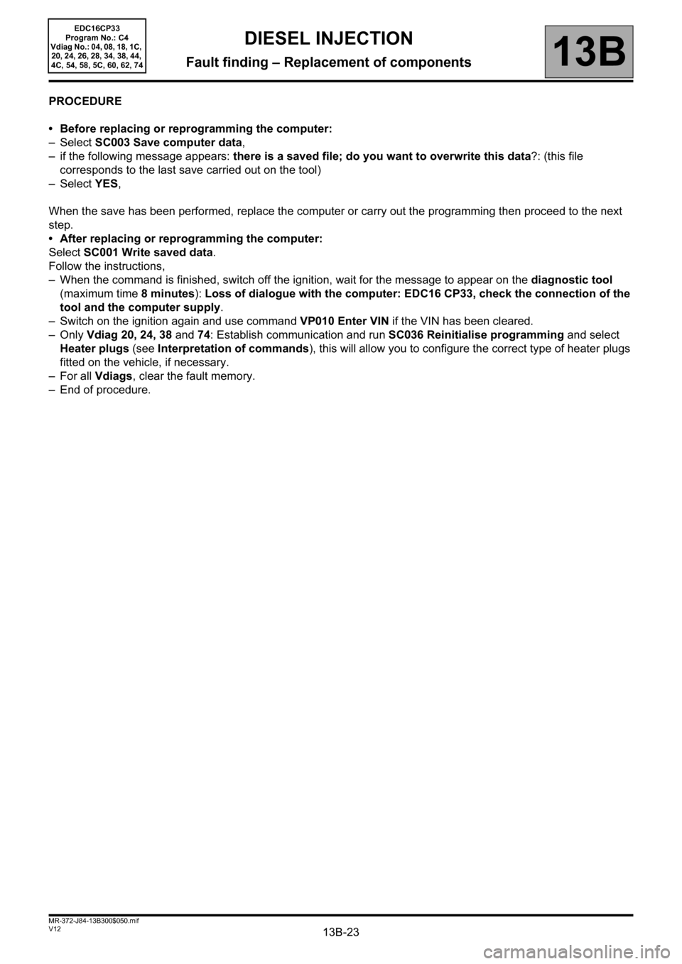
PROCEDURE
• Before replacing or reprogramming the computer:
–Select SC003 Save computer data,
– if the following message appears: there is a saved file; do you want to overwrite this data?: (this file
corresponds to the last save carried out on the tool)
–Select YES,
When the save has been performed, replace the computer or carry out the programming then proceed to the next
step.
• After replacing or reprogramming the computer:
Select SC001 Write saved data.
Follow the instructions,
– When the command is finished, switch off the ignition, wait for the message to appear on the diagnostic tool
(maximum time 8 minutes): Loss of dialogue with the computer: EDC16 CP33, check the connection of the
tool and the computer supply.
– Switch on the ignition again and use command VP010 Enter VIN if the VIN has been cleared.
–Only Vdiag 20, 24, 38 and 74: Establish communication and run SC036 Reinitialise programming and select
Heater plugs (see Interpretation of commands), this will allow you to configure the correct type of heater plugs
fitted on the vehicle, if necessary.
– For all Vdiags, clear the fault memory.
– End of procedure.
Page 24 of 510
13B-24V12 MR-372-J84-13B300$050.mif
DIESEL INJECTION
Fault finding – Replacement of components13B
EDC16CP33
Program No.: C4
Vdiag No.: 04, 08, 18, 1C,
20, 24, 26, 28, 34, 38, 44,
4C, 54, 58, 5C, 60, 62, 74
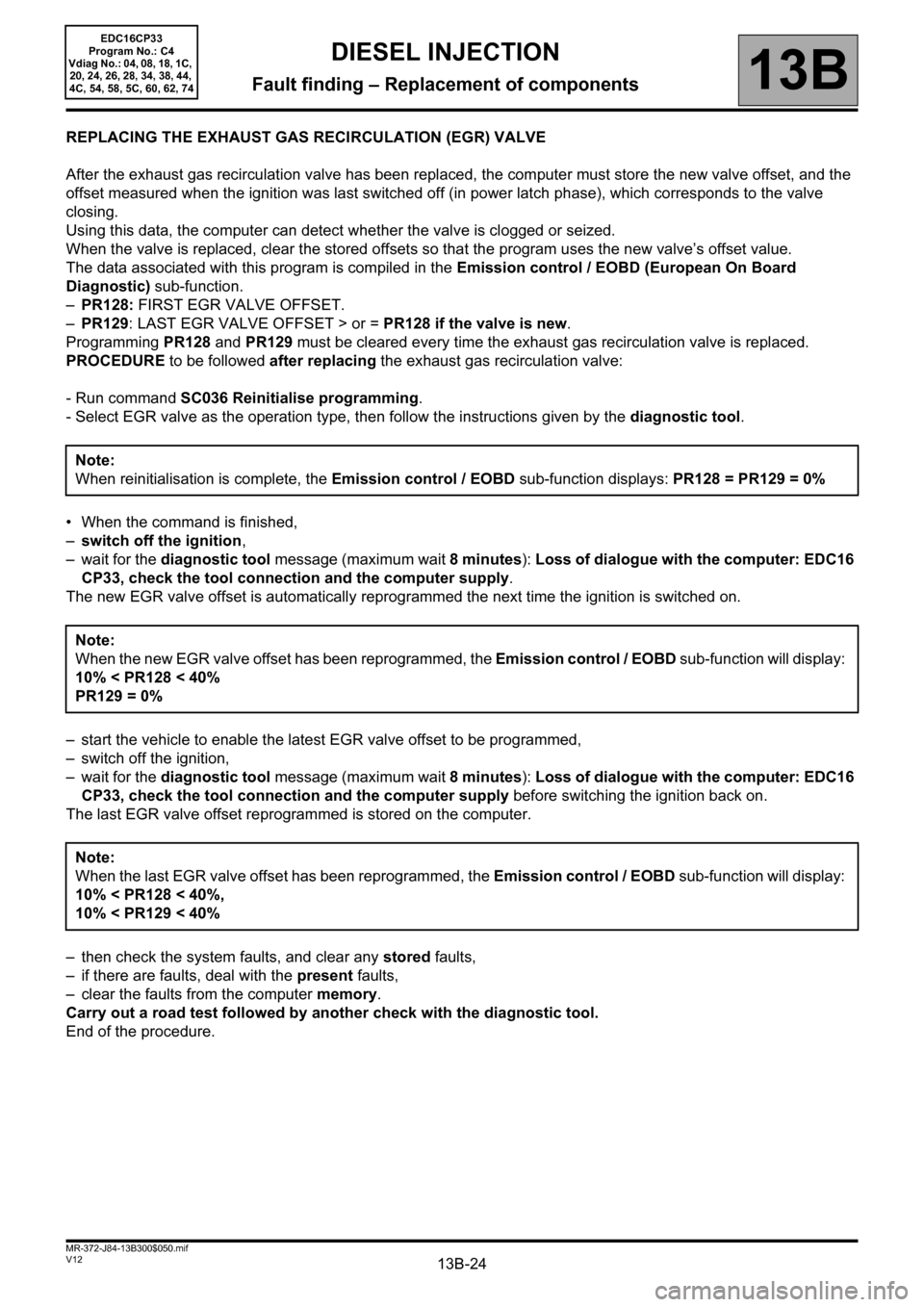
REPLACING THE EXHAUST GAS RECIRCULATION (EGR) VALVE
After the exhaust gas recirculation valve has been replaced, the computer must store the new valve offset, and the
offset measured when the ignition was last switched off (in power latch phase), which corresponds to the valve
closing.
Using this data, the computer can detect whether the valve is clogged or seized.
When the valve is replaced, clear the stored offsets so that the program uses the new valve’s offset value.
The data associated with this program is compiled in the Emission control / EOBD (European On Board
Diagnostic) sub-function.
–PR128: FIRST EGR VALVE OFFSET.
–PR129: LAST EGR VALVE OFFSET > or = PR128 if the valve is new.
Programming PR128 and PR129 must be cleared every time the exhaust gas recirculation valve is replaced.
PROCEDURE to be followed after replacing the exhaust gas recirculation valve:
- Run command SC036 Reinitialise programming.
- Select EGR valve as the operation type, then follow the instructions given by the diagnostic tool.
• When the command is finished,
–switch off the ignition,
– wait for the diagnostic tool message (maximum wait 8 minutes): Loss of dialogue with the computer: EDC16
CP33, check the tool connection and the computer supply.
The new EGR valve offset is automatically reprogrammed the next time the ignition is switched on.
– start the vehicle to enable the latest EGR valve offset to be programmed,
– switch off the ignition,
– wait for the diagnostic tool message (maximum wait 8 minutes): Loss of dialogue with the computer: EDC16
CP33, check the tool connection and the computer supply before switching the ignition back on.
The last EGR valve offset reprogrammed is stored on the computer.
– then check the system faults, and clear any stored faults,
– if there are faults, deal with the present faults,
– clear the faults from the computer memory.
Carry out a road test followed by another check with the diagnostic tool.
End of the procedure.Note:
When reinitialisation is complete, the Emission control / EOBD sub-function displays: PR128 = PR129 = 0%
Note:
When the new EGR valve offset has been reprogrammed, the Emission control / EOBD sub-function will display:
10% < PR128 < 40%
PR129 = 0%
Note:
When the last EGR valve offset has been reprogrammed, the Emission control / EOBD sub-function will display:
10% < PR128 < 40%,
10% < PR129 < 40%
Page 25 of 510
13B-25V12 MR-372-J84-13B300$050.mif
DIESEL INJECTION
Fault finding – Replacement of components13B
EDC16CP33
Program No.: C4
Vdiag No.: 04, 08, 18, 1C,
20, 24, 26, 28, 34, 38, 44,
4C, 54, 58, 5C, 60, 62, 74
REPLACING THE INJECTORS
After one or more injectors have been replaced, enter the IMA codes again and then run command SC036
Reinitialise programming.
To do this, record the IMA code(s) etched on the injector bodies, and enter the codes into the computer using
command SC002 Enter injector codes, and follow the instructions given by the diagnostic tool. Run command
SC036 Reinitialise programming and select injectors, then follow the procedure. Note:
The "IMA" code (individual injector correction) is a calibration with corrective values unique to each injector,
and is used to adjust their flow accurately (injector classification). This correction takes into account mechanical
variances and the variances of the piezo actuator. An injector's class is determined by measurements taken at
different pressures on a test bench. The IMA class identification (7-character alphanumeric code) is then
engraved on the collar of the injector.
The IMA codes must be read from left to right:
– Foolproofing for reading the IMA codes is carried out using the low pressure return connector and/or the
electrical connector on the injector.
– This reading direction is valid when these connectors are located to the left of the cotech.
The IMA codes are read from left to right (see illustration in MR 402 (Vel Satis ph2), MR 395 (Laguna II ph2),
MR 364 (Mégane II ph2), MR 370 (Scénic II ph2), MR 405 (Espace IV ph2) Mechanical, 13B Diesel injection,
Diesel injector, Removal – Refitting)
Note: When entering characters, confusion can arise between:
– Figure 1 and the letters I and L,
– Figure 2 and the letter Z,
– Figure 5 and the letter S,
– Figure 6 and the letter G,
– Figure 8 and the letter B.
After programming or reprogramming the computer, it is essential to enter the 4 injector codes before confirming
the entry.
These individual corrective values are then written to the computer EEPROM, which can then control the injectors,
taking into account their manufacturing variation.
IMPORTANT:
Engines can only operate correctly if the correct IMA* codes have been entered. If no code has been
entered, or if an invalid code has been entered, fault DF066 Injector code(s) is present and the engine will
run in defect mode (engine speed limited significantly). If another injector's code has been entered, the
system will accept it but will make the wrong correction. This could lead to engine damage, loss of
performance and excessive pollution.
Always use the correct injector codes for the engine cylinder/computer.
Note:
On the M9R engine (Renault - Nissan partnership engine), cylinder no. 1 is located at the timing end.
Page 27 of 510
13B-27V12 MR-372-J84-13B300$050.mif
DIESEL INJECTION
Fault finding – Replacement of components13B
EDC16CP33
Program No.: C4
Vdiag No.: 04, 08, 18, 1C,
20, 24, 26, 28, 34, 38, 44,
4C, 54, 58, 5C, 60, 62, 74
REPLACING THE DAMPER VALVE
After replacing the damper valve, run command SC036 Reinitialise programming and select damper valve.
When the command is complete, switch off the ignition and exit fault finding mode.
Wait for the diagnostic tool message (maximum wait 8 minutes): Loss of dialogue with the computer: EDC16
CP33, check the tool connection and the computer supply before switching the ignition back on.
REPLACING THE PARTICLE FILTER (Vdiag: 18, 1C, 54, 20, 58, 5C, 24, 26, 28, 60 and 62 only)
After replacing the particle filter, reconfigure the computer.
The system must be configured via the diagnostic socket using the RENAULT CLIP tool.
Carry out the following steps:
– switch on the ignition,
– run command SC036,
–select After particle filter replacement as the operation type and follow the instructions,
–switch off the ignition and wait for the diagnostic tool message (maximum wait 8 minutes): Loss of dialogue
with the computer: EDC16 CP33, check the tool connection and the computer supply voltage,
– then switch on the ignition again,
–clear the faults from the computer memory (this operation must be carried out within 3 minutes of the ignition
being switched on)
Carry out a road test followed by a complete check with the diagnostic tool.
REPLACING THE HEATER PLUGS (Vdiag 20, 24, 38 and 74 only)
SLOW plugs are identified by a black ring.
FAST plugs are identified by a white ring.
After replacing the heater plugs with plugs of a different type, reconfigure the type of plugs fitted on the vehicle.
Carry out the following steps:
– switch on the ignition,
– run command SC036 Reinitialise programming,
–select Heater plugs as the operation type and follow the instructions,
–switch off the ignition and wait for the diagnostic tool message (maximum wait 8 minutes): Loss of dialogue
with the computer: EDC16 CP33, check the tool connection and the computer supply voltage,
– then switch on the ignition again,
– clear the faults from the computer memory.
Carry out a road test followed by a complete check with the diagnostic tool. Note:
When reinitialisation is complete, the Emission control / EOBD (European On Board Diagnostic) sub-function
displays:
PR858
≠ 0%, PR859 ≠ 0%, PR860 ≠ 0% and PR861 ≠ 0%.
Page 70 of 510
13B-70
AFTER REPAIRDeal with any other faults. Clear the fault memory.
Switch off the ignition until the end of the power-latch phase, and carry out a road test
followed by a check with the diagnostic tool.
V12 MR-372-J84-13B300$071.mif
DIESEL INJECTION
Fault finding – Interpretation of faults13B
EDC16CP33
Program No.: C4
Vdiag No.: 04, 08, 18, 1C,
20, 24, 26, 28, 34, 38, 44,
4C, 54, 58, 5C, 60, 62, 74
DF026
PRESENT
OR
STOREDCYLINDER 1 INJECTOR CONTROL CIRCUIT
CO: Open circuit
CC: Short circuit
1.DEF: Internal electronic fault
NOTESConditions for applying the fault finding procedure to a stored fault:
the fault becomes present after:
– the ignition is switched on.
– the engine is started.
Special notes:
If the fault is present:
–the EOBD (European On Board Diagnostic) warning light is lit,
–the level 2 warning light is lit for CC and 1. DEF (only for M9R760/761),
–the level 1 warning light comes on for CO.
Use bornier Elé.1681 for all operations on the engine management computer.
After replacing an injector, run commands SC002 Enter injector codes (the IMA*
codes are read from left to right) and SC036 Reinitialise programming and follow the
procedure.
IMPORTANT:
– cylinder no.1 is located at the timing end.
– please observe the cleanliness guidelines and safety advice.
– do not disconnect the injectors with the engine running as this may damage the
engine.
Use the Wiring Diagram Technical Note, Laguna II ph2, Vel Satis ph2, Espace IV
ph2, Mégane II ph2, Scénic II ph2.
EDC16CP33_V18_DF026 / EDC16CP33_V1C_DF026 / EDC16CP33_V54_DF026 / EDC16CP33_V20_DF026 / EDC16CP33_V58_DF026 /
EDC16CP33_V5C_DF026 / EDC16CP33_V24_DF026 / EDC16CP33_V04_DF026 / EDC16CP33_V08_DF026 / EDC16CP33_V44_DF026 /
EDC16CP33_V4C_DF026 / EDC16CP33_V34_DF026 / EDC16CP33_V38_DF026 / EDC16CP33_V74_DF026 / EDC16CP33_V28_DF026 /
EDC16CP33_V62_DF026 / EDC16CP33_V26_DF026 / EDC16CP33_V60_DF026
Page 75 of 510
13B-75
AFTER REPAIRDeal with any other faults. Clear the fault memory.
Switch off the ignition until the end of the power-latch phase, and carry out a road test
followed by a check with the diagnostic tool.
V12 MR-372-J84-13B300$071.mif
DIESEL INJECTION
Fault finding – Interpretation of faults13B
EDC16CP33
Program No.: C4
Vdiag No.: 04, 08, 18, 1C,
20, 24, 26, 28, 34, 38, 44,
4C, 54, 58, 5C, 60, 62, 74
DF027
PRESENT
OR
STOREDINJECTOR CYLINDER 2 CONTROL CIRCUIT
CO: Open circuit
CC: Short circuit
1.DEF: Internal electronic fault
NOTESConditions for applying the fault finding procedure to a stored fault:
The fault becomes present after:
– the ignition is switched on.
– the engine is started.
Special notes:
If the fault is present:
–the EOBD (European On Board Diagnostic) warning light is lit
–the level 2 warning light is lit for CC and 1.DEF,
–the level 1 warning light is lit for CO
Use bornier Elé.1681 for all operations on the engine management computer.
After replacing an injector, run commands SC002 Enter injector codes (the IMA*
codes are read from left to right) and SC036 Reinitialise programming and follow the
procedure.
IMPORTANT:
– cylinder no.1 is located at the timing end.
– please observe the cleanliness guidelines and safety advice.
– do not disconnect the injectors with the engine running as this may damage the
engine
Use the Wiring Diagram Technical Note, Laguna II ph2, Vel Satis ph2, Espace IV
ph2, Mégane II ph2, Scénic II ph2.
EDC16CP33_V18_DF027 / EDC16CP33_V1C_DF027 / EDC16CP33_V54_DF027 / EDC16CP33_V20_DF027 / EDC16CP33_V58_DF027 /
EDC16CP33_V5C_DF027 / EDC16CP33_V24_DF027 / EDC16CP33_V04_DF027 / EDC16CP33_V08_DF027 / EDC16CP33_V44_DF027 /
EDC16CP33_V4C_DF027 / EDC16CP33_V34_DF027 / EDC16CP33_V38_DF027 / EDC16CP33_V74_DF027 / EDC16CP33_V28_DF027 /
EDC16CP33_V62_DF027/ EDC16CP33_V26_DF027 / EDC16CP33_V60_DF027
Page 80 of 510
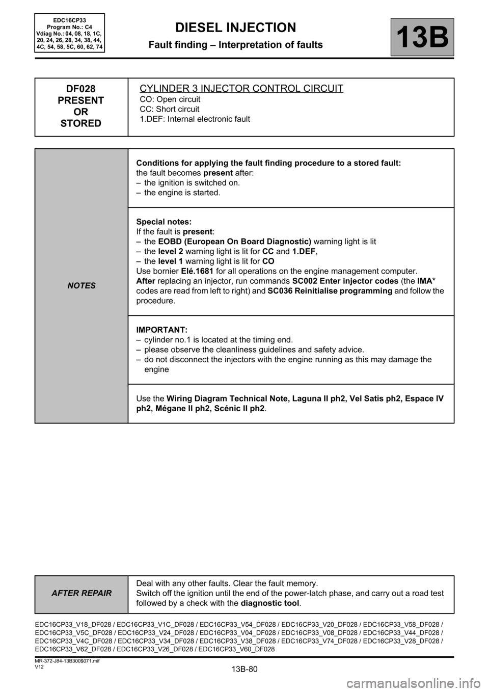
13B-80
AFTER REPAIRDeal with any other faults. Clear the fault memory.
Switch off the ignition until the end of the power-latch phase, and carry out a road test
followed by a check with the diagnostic tool.
V12 MR-372-J84-13B300$071.mif
DIESEL INJECTION
Fault finding – Interpretation of faults13B
EDC16CP33
Program No.: C4
Vdiag No.: 04, 08, 18, 1C,
20, 24, 26, 28, 34, 38, 44,
4C, 54, 58, 5C, 60, 62, 74
DF028
PRESENT
OR
STOREDCYLINDER 3 INJECTOR CONTROL CIRCUIT
CO: Open circuit
CC: Short circuit
1.DEF: Internal electronic fault
NOTESConditions for applying the fault finding procedure to a stored fault:
the fault becomes present after:
– the ignition is switched on.
– the engine is started.
Special notes:
If the fault is present:
–the EOBD (European On Board Diagnostic) warning light is lit
–the level 2 warning light is lit for CC and 1.DEF,
–the level 1 warning light is lit for CO
Use bornier Elé.1681 for all operations on the engine management computer.
After replacing an injector, run commands SC002 Enter injector codes (the IMA*
codes are read from left to right) and SC036 Reinitialise programming and follow the
procedure.
IMPORTANT:
– cylinder no.1 is located at the timing end.
– please observe the cleanliness guidelines and safety advice.
– do not disconnect the injectors with the engine running as this may damage the
engine
Use the Wiring Diagram Technical Note, Laguna II ph2, Vel Satis ph2, Espace IV
ph2, Mégane II ph2, Scénic II ph2.
EDC16CP33_V18_DF028 / EDC16CP33_V1C_DF028 / EDC16CP33_V54_DF028 / EDC16CP33_V20_DF028 / EDC16CP33_V58_DF028 /
EDC16CP33_V5C_DF028 / EDC16CP33_V24_DF028 / EDC16CP33_V04_DF028 / EDC16CP33_V08_DF028 / EDC16CP33_V44_DF028 /
EDC16CP33_V4C_DF028 / EDC16CP33_V34_DF028 / EDC16CP33_V38_DF028 / EDC16CP33_V74_DF028 / EDC16CP33_V28_DF028 /
EDC16CP33_V62_DF028 / EDC16CP33_V26_DF028 / EDC16CP33_V60_DF028
Page 85 of 510
13B-85
AFTER REPAIRDeal with any other faults. Clear the fault memory.
Switch off the ignition until the end of the power-latch phase, and carry out a road test
followed by a check with the diagnostic tool.
V12 MR-372-J84-13B300$071.mif
DIESEL INJECTION
Fault finding – Interpretation of faults13B
EDC16CP33
Program No.: C4
Vdiag No.: 04, 08, 18, 1C,
20, 24, 26, 28, 34, 38, 44,
4C, 54, 58, 5C, 60, 62, 74
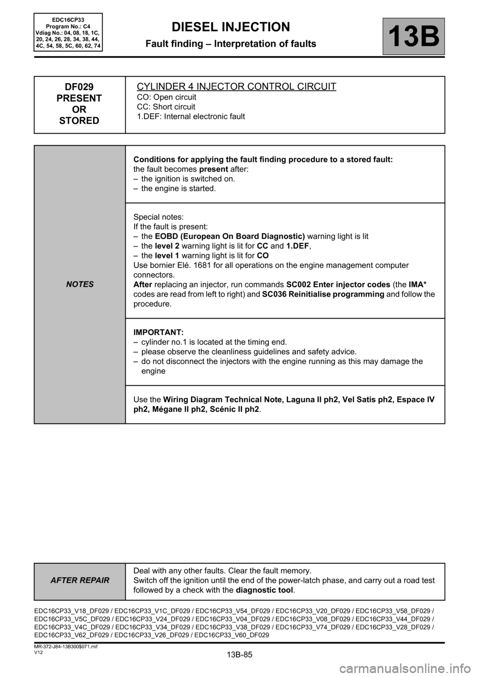
DF029
PRESENT
OR
STOREDCYLINDER 4 INJECTOR CONTROL CIRCUIT
CO: Open circuit
CC: Short circuit
1.DEF: Internal electronic fault
NOTESConditions for applying the fault finding procedure to a stored fault:
the fault becomes present after:
– the ignition is switched on.
– the engine is started.
Special notes:
If the fault is present:
–the EOBD (European On Board Diagnostic) warning light is lit
–the level 2 warning light is lit for CC and 1.DEF,
–the level 1 warning light is lit for CO
Use bornier Elé. 1681 for all operations on the engine management computer
connectors.
After replacing an injector, run commands SC002 Enter injector codes (the IMA*
codes are read from left to right) and SC036 Reinitialise programming and follow the
procedure.
IMPORTANT:
– cylinder no.1 is located at the timing end.
– please observe the cleanliness guidelines and safety advice.
– do not disconnect the injectors with the engine running as this may damage the
engine
Use the Wiring Diagram Technical Note, Laguna II ph2, Vel Satis ph2, Espace IV
ph2, Mégane II ph2, Scénic II ph2.
EDC16CP33_V18_DF029 / EDC16CP33_V1C_DF029 / EDC16CP33_V54_DF029 / EDC16CP33_V20_DF029 / EDC16CP33_V58_DF029 /
EDC16CP33_V5C_DF029 / EDC16CP33_V24_DF029 / EDC16CP33_V04_DF029 / EDC16CP33_V08_DF029 / EDC16CP33_V44_DF029 /
EDC16CP33_V4C_DF029 / EDC16CP33_V34_DF029 / EDC16CP33_V38_DF029 / EDC16CP33_V74_DF029 / EDC16CP33_V28_DF029 /
EDC16CP33_V62_DF029 / EDC16CP33_V26_DF029 / EDC16CP33_V60_DF029