Wiring diagrams RENAULT SCENIC 2012 J95 / 3.G Engine And Peripherals EDC16CP33 Workshop Manual
[x] Cancel search | Manufacturer: RENAULT, Model Year: 2012, Model line: SCENIC, Model: RENAULT SCENIC 2012 J95 / 3.GPages: 510, PDF Size: 2.98 MB
Page 2 of 510

13B-2V12 MR-372-J84-13B300$010.mif
13B
EDC16CP33
Program No.: C4
Vdiag No.: 04, 08, 18, 1C,
20, 24, 26, 28, 34, 38, 44,
4C, 54, 58, 5C, 60, 62, 74
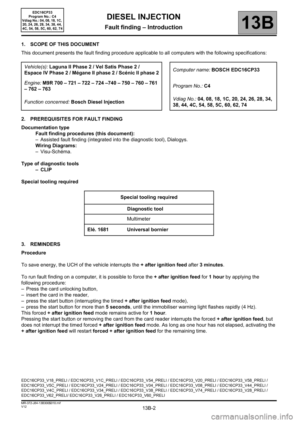
1. SCOPE OF THIS DOCUMENT
This document presents the fault finding procedure applicable to all computers with the following specifications:
2. PREREQUISITES FOR FAULT FINDING
Documentation type
Fault finding procedures (this document):
– Assisted fault finding (integrated into the diagnostic tool), Dialogys.
Wiring Diagrams:
–Visu-Schéma.
Type of diagnostic tools
–CLIP
Special tooling required
3. REMINDERS
Procedure
To save energy, the UCH of the vehicle interrupts the + after ignition feed after 3 minutes.
To run fault finding on a computer, it is possible to force the + after ignition feed for 1 hour by applying the
following procedure:
– Press the card unlocking button,
– insert the card in the reader,
– press the start button (interrupting the timed + after ignition feed mode),
– press the start button for more than 5 seconds, until the immobiliser warning light flashes rapidly (4 Hz).
This forced + after ignition feed mode remains active for 1 hour.
Pressing the start button or removing the card from the card reader interrupts the forced + after ignition feed, but
does not interrupt the timed forced + after ignition feed mode. As long as one hour has not elapsed, activating the
+ after ignition feed will restart forced + after ignition feed for the remaining time. Vehicle(s): Laguna II Phase 2 / Vel Satis Phase 2 /
Espace IV Phase 2 / Mégane II phase 2 / Scénic II phase 2Computer name: BOSCH EDC16CP33
Engine: M9R 700 – 721 – 722 – 724 –740 – 750 – 760 – 761
– 762 – 763Program No.: C4
Function concerned: Bosch Diesel InjectionVdiag No.: 04, 08, 18, 1C, 20, 24, 26, 28, 34,
38, 44, 4C, 54, 58, 5C, 60, 62, 74
Special tooling required
Diagnostic tool
Multimeter
Elé. 1681 Universal bornier
EDC16CP33_V18_PRELI / EDC16CP33_V1C_PRELI / EDC16CP33_V54_PRELI / EDC16CP33_V20_PRELI / EDC16CP33_V58_PRELI /
EDC16CP33_V5C_PRELI / EDC16CP33_V24_PRELI / EDC16CP33_V04_PRELI / EDC16CP33_V08_PRELI / EDC16CP33_V44_PRELI /
EDC16CP33_V4C_PRELI / EDC16CP33_V34_PRELI / EDC16CP33_V38_PRELI / EDC16CP33_V74_PRELI / EDC16CP33_V28_PRELI /
EDC16CP33_V62_PRELI/ EDC16CP33_V26_PRELI / EDC16CP33_V60_PRELI
DIESEL INJECTION
Fault finding – Introduction
Page 448 of 510

13B-448V12 MR-372-J84-13B300$150.mif
DIESEL INJECTION
Fault finding – Interpretation of commands13B
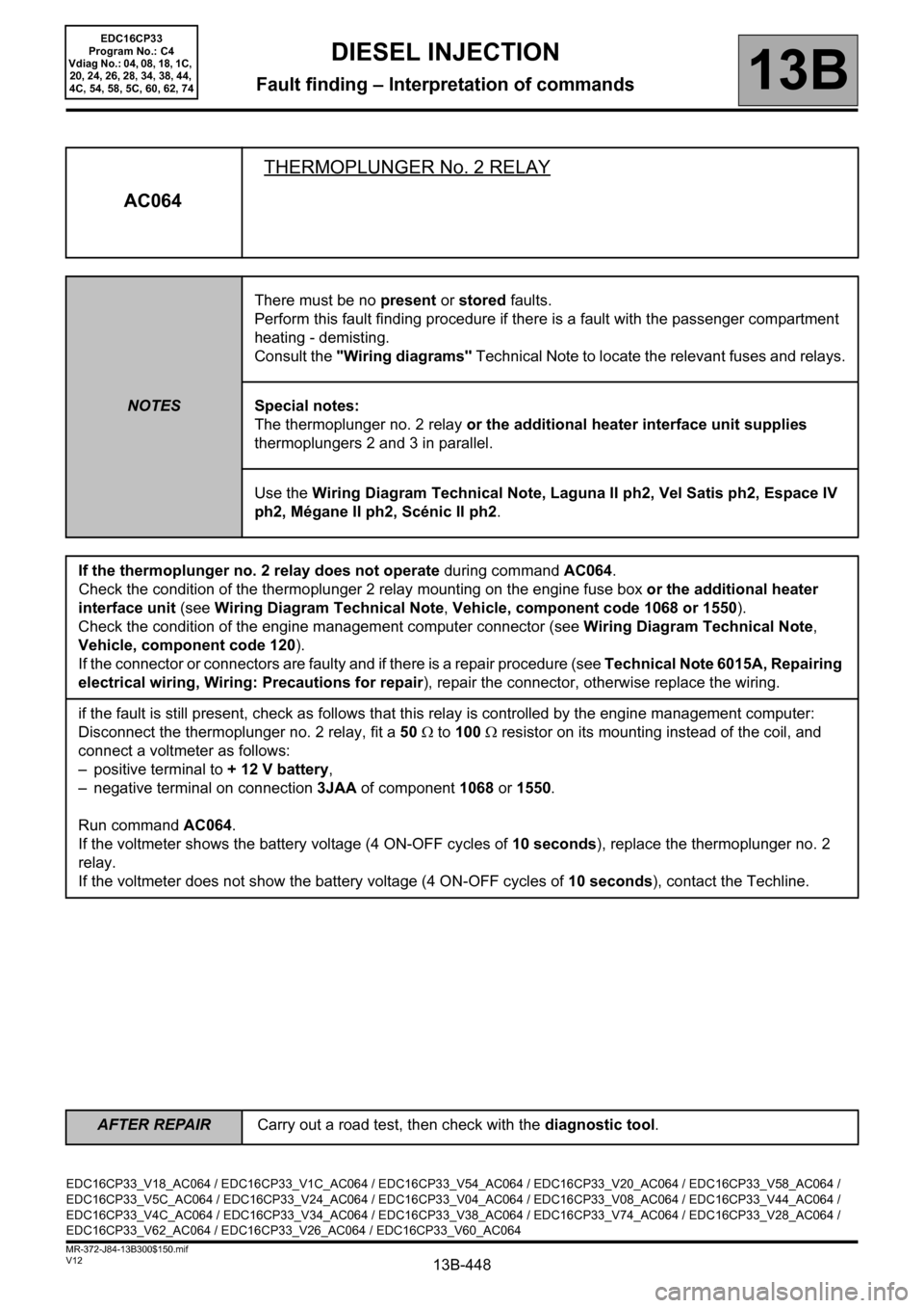
AC064THERMOPLUNGER No. 2 RELAY
NOTESThere must be no present or stored faults.
Perform this fault finding procedure if there is a fault with the passenger compartment
heating - demisting.
Consult the "Wiring diagrams" Technical Note to locate the relevant fuses and relays.
Special notes:
The thermoplunger no. 2 relay or the additional heater interface unit supplies
thermoplungers 2 and 3 in parallel.
Use the Wiring Diagram Technical Note, Laguna II ph2, Vel Satis ph2, Espace IV
ph2, Mégane II ph2, Scénic II ph2.
If the thermoplunger no. 2 relay does not operate during command AC064.
Check the condition of the thermoplunger 2 relay mounting on the engine fuse box or the additional heater
interface unit (see Wiring Diagram Technical Note, Vehicle, component code 1068 or 1550).
Check the condition of the engine management computer connector (see Wiring Diagram Technical Note,
Vehicle, component code 120).
If the connector or connectors are faulty and if there is a repair procedure (see Technical Note 6015A, Repairing
electrical wiring, Wiring: Precautions for repair), repair the connector, otherwise replace the wiring.
if the fault is still present, check as follows that this relay is controlled by the engine management computer:
Disconnect the thermoplunger no. 2 relay, fit a 50 Ω to 100 Ω resistor on its mounting instead of the coil, and
connect a voltmeter as follows:
– positive terminal to + 12 V battery,
– negative terminal on connection 3JAA of component 1068 or 1550.
Run command AC064.
If the voltmeter shows the battery voltage (4 ON-OFF cycles of 10 seconds), replace the thermoplunger no. 2
relay.
If the voltmeter does not show the battery voltage (4 ON-OFF cycles of 10 seconds), contact the Techline.
EDC16CP33_V18_AC064 / EDC16CP33_V1C_AC064 / EDC16CP33_V54_AC064 / EDC16CP33_V20_AC064 / EDC16CP33_V58_AC064 /
EDC16CP33_V5C_AC064 / EDC16CP33_V24_AC064 / EDC16CP33_V04_AC064 / EDC16CP33_V08_AC064 / EDC16CP33_V44_AC064 /
EDC16CP33_V4C_AC064 / EDC16CP33_V34_AC064 / EDC16CP33_V38_AC064 / EDC16CP33_V74_AC064 / EDC16CP33_V28_AC064 /
EDC16CP33_V62_AC064 / EDC16CP33_V26_AC064 / EDC16CP33_V60_AC064
EDC16CP33
Program No.: C4
Vdiag No.: 04, 08, 18, 1C,
20, 24, 26, 28, 34, 38, 44,
4C, 54, 58, 5C, 60, 62, 74
AFTER REPAIRCarry out a road test, then check with the diagnostic tool.