engine overheat RENAULT SCENIC 2012 J95 / 3.G Engine And Peripherals EDC16CP33 Workshop Manual
[x] Cancel search | Manufacturer: RENAULT, Model Year: 2012, Model line: SCENIC, Model: RENAULT SCENIC 2012 J95 / 3.GPages: 510, PDF Size: 2.98 MB
Page 14 of 510
13B-14V12 MR-372-J84-13B300$030.mif
DIESEL INJECTION
Fault finding – System operation13B
EDC16CP33
Program No.: C4
Vdiag No.: 04, 08, 18, 1C,
20, 24, 26, 28, 34, 38, 44,
4C, 54, 58, 5C, 60, 62, 74
c. Functions hosted:
Air conditioning management assistance:
For vehicles with air conditioning, the EDC16CP33 system provides the option of deactivating the air conditioning
via the UCH, under certain conditions of use:
– when requested by the driver,
– when starting the engine,
– if the engine overheats (in order to reduce the power the engine has to supply),
– when the engine speed is kept at a very high level (to protect the compressor),
– during transition phases (e.g. under heavy acceleration when overtaking, anti-stalling and moving off strategies).
These conditions are only taken into account when they do not occur repeatedly, in order to prevent system
instabilities (erratic deactivations),
– when certain faults appear.
I - Cold loop air conditioning management:
The air conditioning is the cold loop type and its management shared between several computers.
The injection computer is responsible for:
– authorising requests for cold air depending on the engine coolant temperature and the engine speed,
– calculating the power absorbed by the compressor from the refrigerant pressure.
–requesting fan assembly actuation (Mégane II ph2 and Scénic II ph2) and controlling fan assembly actuation
(Laguna II, Vel Satis ph2 and Espace IV ph2), according to the vehicle speed, the refrigerant pressure and the
engine coolant temperature.
The driver requests the air conditioning to be switched on by means of the ventilation selector coupled to a switch.
The cold air request is authorised or denied depending on the pressure measured. If this pressure is outside the
operating limits, the cold loop program is not activated.
The air conditioning system is authorised by the injection computer 2 to 8 seconds after the engine is started.
Management of the thermoplungers:
To improve cold starting, the vehicle is fitted with thermoplungers. These thermoplungers are managed and
controlled by the injection computer, according to the operating phases, primarily to accelerate the increase in
engine coolant temperature.
The maximum number of thermoplungers that can be actuated is four and their actuation depends mainly on the
coolant temperature and the air temperature.
See configuration reading LC056 Thermoplungers: WITH or WITHOUT.
When necessary, they are actuated by the injection system only during particle filter regeneration by means
of a special unit.
The maximum number of thermoplungers that can be managed is four and their activation depends mainly on the
coolant temperature (< 15°C) and air temperature (< 5°C).
Page 19 of 510
13B-19V12 MR-372-J84-13B300$030.mif
DIESEL INJECTION
Fault finding – System operation13B
EDC16CP33
Program No.: C4
Vdiag No.: 04, 08, 18, 1C,
20, 24, 26, 28, 34, 38, 44,
4C, 54, 58, 5C, 60, 62, 74
Warning light management:
Instrument panel display
The computer displays certain information on the instrument panel relating to engine operation. This concerns five
functions:
– the pre-postheating warning light,
– the coolant temperature warning light,
–the level 1 fault warning light (non-critical fault),
–the level 2 fault warning light (emergency stop),
–the EOBD (European On Board Diagnostic) warning light,
These six functions are represented by 3 warning lights and/or messages displayed by the on-board computer.
Orange pre-post heating/non-critical fault SERVICE warning light (severity 1)
This light is used both as an in-operation indicator light and as a system fault indicator:
– Continuously lit with + after ignition feed:
Indicates preheating of the spark plugs.
– Continuously lit with the Check injection message:
Indicates a level 1 fault (involving operation of the injection system in defect mode).
The driver should have the repairs carried out as soon as possible.
Temperature / red emergency STOP warning light (level 2)
This indicator light is used both as an in-operation indicator light and as a system fault warning light. It lights up for
3 seconds after the ignition is switched on (automatic test procedure managed by the instrument panel):
– Continuously lit:
Indicates engine overheating (the driver is free to choose whether or not to stop the vehicle).
– Continuously lit with the faulty injection message:
Indicates a level 2 fault (In this case, the injection is automatically cut after a few seconds).
The driver should carry out repairs as soon as possible.
ORANGE Excessive pollution EOBD warning light
Symbolised by an engine, it lights up for approximately 3 seconds when the ignition is switched on.
This warning light comes on if the system has one or more EOBD faults.
This warning light is used to alert the driver to injection faults that could lead to excessive pollution, or if the EOBD
system (European On Board Diagnostic) has been deactivated.
The injection computer requests illumination of the EOBD warning light for a present fault only after three
consecutive driving cycles.
The 3 second visual inspection when the ignition is switched on (automatic test procedure managed by the
instrument panel) is carried out by the injection computer.
Special particle filter ORANGE warning light or warning message (depending on instrument panel)
Only for Vdiag: 18, 1C, 54, 20, 58, 5C, 24, 26 and 60.
This warning light or message is used to warn the driver that the particle filter is loaded with particles, (see the soot
weight thresholds for illumination of the warning light for fault DF312 Speed request) due to driving conditions which
were not suitable for regeneration to take place. The driver must then drive as soon as possible at an average speed
of 48 mph (80 km/h) subject to the road conditions and authorised speed limits, until the warning light goes out.
Page 58 of 510
13B-58
AFTER REPAIRDeal with any other faults. Clear the fault memory.
Switch off the ignition until the end of the power-latch phase, and carry out a road test
followed by a check with the diagnostic tool.
V12 MR-372-J84-13B300$071.mif
DIESEL INJECTION
Fault finding – Interpretation of faults13B
EDC16CP33
Program No.: C4
Vdiag No.: 04, 08, 18, 1C,
20, 24, 26, 28, 34, 38, 44,
4C, 54, 58, 5C, 60, 62, 74
DF017
CONTINUED 3
1.DEFNOTESSpecial notes:
This fault occurs if the computer's control section overheats
when command AC037 Preheating relay is run or during
normal operation of the preheating unit.
Check the condition of the preheating unit connector (see Wiring Diagram Technical Note, Laguna II ph2, Vel
Satis ph2, Espace IV ph2, Mégane II ph2, Scénic II ph2, component code 257).
Check the condition of the engine management computer connector (see Wiring Diagram Technical Note,
Laguna II ph2, Vel Satis ph2, Espace IV ph2, Mégane II ph2, Scénic II ph2, component code 120).
If the connector or connectors are faulty and if there is a repair procedure (see Technical Note 6015A, Repairing
electrical wiring, Wiring: Precautions for repair), repair the connector, otherwise replace the wiring.
Check the continuity and absence of interference resistance on the following connection:
•3FF between components120 and 257.
Check the + 12 V battery supply to the preheating unit:
•BP35 of component 257.
If the connection or connections are faulty and if there is a repair method (see Technical Note 6015A, Electrical
wiring repair, Wiring: Precautions for repair), repair the wiring, otherwise replace the wiring.
If the fault is still present, contact the Techline.
Page 62 of 510
13B-62
AFTER REPAIRDeal with any other faults. Clear the fault memory.
Switch off the ignition until the end of the power-latch phase, and carry out a road test
followed by a check with the diagnostic tool.
V12 MR-372-J84-13B300$071.mif
DIESEL INJECTION
Fault finding – Interpretation of faults13B
EDC16CP33
Program No.: C4
Vdiag No.: 04, 08, 18, 1C,
20, 24, 26, 28, 34, 38, 44,
4C, 54, 58, 5C, 60, 62, 74
DF018
CONTINUED 3
1.DEFNOTESSpecial notes:
This fault occurs if the computer's control section overheats
when command AC154 Low speed fan assembly is run or
during normal operation of the fan assembly relay.
Check the condition of the low speed fan assembly relay mounting connector (see Wiring Diagram Technical
Note, Laguna II ph2, Vel Satis ph2, Espace IV ph2, Mégane II ph2, Scénic II ph2, component code 700 or
336).
Check the condition of the engine management computer connector (see Wiring Diagram Technical Note,
Laguna II ph2, Vel Satis ph2, Espace IV ph2, Mégane II ph2, Scénic II ph2, component code 120).
If the connector or connectors are faulty and if there is a repair procedure (see Technical Note 6015A, Repairing
electrical wiring, Wiring: Precautions for repair), repair the connector, otherwise replace the wiring.
Measure the resistance of the low-speed fan assembly relay coil.
IMPORTANT:
Respect the measuring direction (polarity) as a protection diode is used.
Replace the relay if the resistance of the relay coil is greater than 200 Ω or less than 20 Ω.
Remove the low speed relay and check the insulation and continuity of the following connection:
•3JN between components 120 and 700 or 336.
Check the + 12 V after relay supply to the low speed fan assembly relay.
•3FB of component 700 or 336.
If the connection or connections are faulty and if there is a repair method (see Technical Note 6015A, Electrical
wiring repair, Wiring: Precautions for repair), repair the wiring, otherwise replace the wiring.
If the fault is still present, contact the Techline.
Page 66 of 510
13B-66
AFTER REPAIRDeal with any other faults. Clear the fault memory.
Switch off the ignition until the end of the power-latch phase, and carry out a road test
followed by a check with the diagnostic tool.
V12 MR-372-J84-13B300$071.mif
DIESEL INJECTION
Fault finding – Interpretation of faults13B
EDC16CP33
Program No.: C4
Vdiag No.: 04, 08, 18, 1C,
20, 24, 26, 28, 34, 38, 44,
4C, 54, 58, 5C, 60, 62, 74
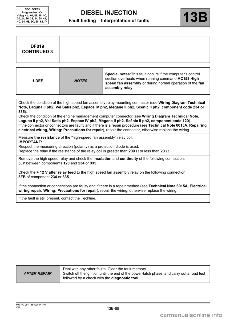
DF019
CONTINUED 3
1.DEFNOTESSpecial notes:This fault occurs if the computer's control
section overheats when running command AC153 High
speed fan assembly or during normal operation of the fan
assembly relay.
Check the condition of the high speed fan assembly relay mounting connector (see Wiring Diagram Technical
Note, Laguna II ph2, Vel Satis ph2, Espace IV ph2, Mégane II ph2, Scénic II ph2, component code 234 or
335).
Check the condition of the engine management computer connector (see Wiring Diagram Technical Note,
Laguna II ph2, Vel Satis ph2, Espace IV ph2, Mégane II ph2, Scénic II ph2, component code 120).
If the connector or connectors are faulty and if there is a repair procedure (see Technical Note 6015A, Repairing
electrical wiring, Wiring: Precautions for repair), repair the connector, otherwise replace the wiring.
Measure the resistance of the "high-speed fan assembly" relay coil.
IMPORTANT:
Respect the measuring direction (polarity) as a protection diode is used.
Replace the relay if the resistance of the relay coil is greater than 200 Ω or less than 20 Ω.
Remove the high speed relay and check the insulation and continuity of the following connection:
3JP between components 120 and 234 or 335.
Check the + 12 V after relay feed to the high speed fan assembly relay on the following connection:
3FB of component 234 or 335.
If the connection or connections are faulty and if there is a repair method (see Technical Note 6015A, Electrical
wiring repair, Wiring: Precautions for repair), repair the wiring, otherwise replace the wiring.
If the fault is still present, contact the Techline.
Page 93 of 510
13B-93
AFTER REPAIRDeal with any other faults. Clear the fault memory.
Switch off the ignition until the end of the power-latch phase, and carry out a road test
followed by a check with the diagnostic tool.
V12 MR-372-J84-13B300$071.mif
DIESEL INJECTION
Fault finding – Interpretation of faults13B
EDC16CP33
Program No.: C4
Vdiag No.: 04, 08, 18, 1C,
20, 24, 26, 28, 34, 38, 44,
4C, 54, 58, 5C, 60, 62, 74
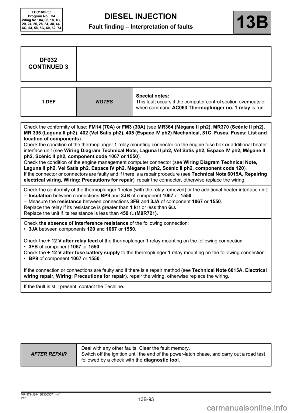
DF032
CONTINUED 3
1.DEFNOTESSpecial notes:
This fault occurs if the computer control section overheats or
when command AC063 Thermoplunger no. 1 relay is run.
Check the conformity of fuse: FM14 (70A) or FM3 (30A) (see MR364 (Mégane II ph2), MR370 (Scénic II ph2),
MR 395 (Laguna II ph2), 402 (Vel Satis ph2), 405 (Espace IV ph2) Mechanical, 81C, Fuses, Fuses: List and
location of components).
Check the condition of the thermoplunger 1 relay mounting connector on the engine fuse box or additional heater
interface unit (see Wiring Diagram Technical Note, Laguna II ph2, Vel Satis ph2, Espace IV ph2, Mégane II
ph2, Scénic II ph2, component code 1067 or 1550).
Check the condition of the engine management computer connector (see Wiring Diagram Technical Note,
Laguna II ph2, Vel Satis ph2, Espace IV ph2, Mégane II ph2, Scénic II ph2, component code 120).
If the connector or connectors are faulty and if there is a repair procedure (see Technical Note 6015A, Repairing
electrical wiring, Wiring: Precautions for repair), repair the connector, otherwise replace the wiring.
Check the conformity of the thermoplunger 1 relay (with the relay removed) or the additional heater interface unit:
–Insulation between connections BP9 and 3JB of component 1067 or 1550.
– Measure the resistance between connections3FB and 3JA of component1067 or 1550.
Replace the relay if its resistance is greater than 1 kΩ or less than 6Ω.
Replace the unit if its resistance is less than 450 Ω (M9R721).
Check the absence of interference resistance of the following connection:
•3JA between components 120 and 1067 or 1550.
Check the + 12 V after relay feed of the thermoplunger 1 relay mounting on the following connection:
•3FB of component 1067 or
1550.
Check the + 12 V after fuse battery supply to the thermoplunger 1 relay mounting on the following connection:
•BP9 of component 1067 or 1550.
If the connection or connections are faulty and if there is a repair method (see Technical Note 6015A, Electrical
wiring repair, Wiring: Precautions for repair), repair the wiring, otherwise replace the wiring.
If the fault is still present, contact the Techline.
Page 97 of 510
13B-97
AFTER REPAIRDeal with any other faults. Clear the fault memory.
Switch off the ignition until the end of the power-latch phase, and carry out a road test
followed by a check with the diagnostic tool.
V12 MR-372-J84-13B300$072.mif
DIESEL INJECTION
Fault finding – Interpretation of faults13B
EDC16CP33
Program No.: C4
Vdiag No.: 04, 08, 18, 1C,
20, 24, 26, 28, 34, 38, 44,
4C, 54, 58, 5C, 60, 62, 74
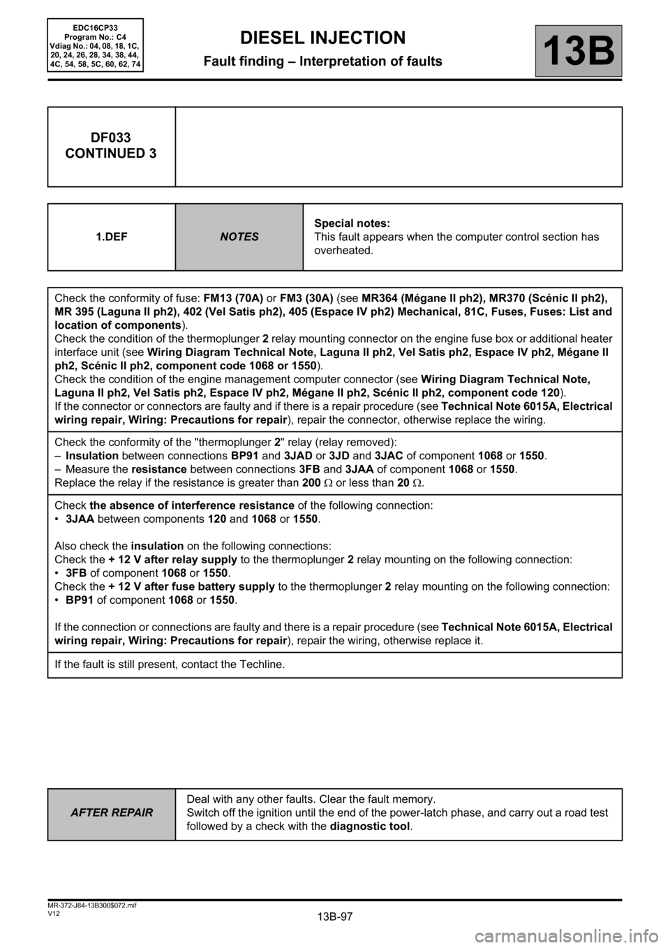
DF033
CONTINUED 3
1.DEFNOTESSpecial notes:
This fault appears when the computer control section has
overheated.
Check the conformity of fuse: FM13 (70A) or FM3 (30A) (see MR364 (Mégane II ph2), MR370 (Scénic II ph2),
MR 395 (Laguna II ph2), 402 (Vel Satis ph2), 405 (Espace IV ph2) Mechanical, 81C, Fuses, Fuses: List and
location of components).
Check the condition of the thermoplunger 2 relay mounting connector on the engine fuse box or additional heater
interface unit (see Wiring Diagram Technical Note, Laguna II ph2, Vel Satis ph2, Espace IV ph2, Mégane II
ph2, Scénic II ph2, component code 1068 or 1550).
Check the condition of the engine management computer connector (see Wiring Diagram Technical Note,
Laguna II ph2, Vel Satis ph2, Espace IV ph2, Mégane II ph2, Scénic II ph2, component code 120).
If the connector or connectors are faulty and if there is a repair procedure (see Technical Note 6015A, Electrical
wiring repair, Wiring: Precautions for repair), repair the connector, otherwise replace the wiring.
Check the conformity of the "thermoplunger 2" relay (relay removed):
–Insulation between connections BP91 and 3JAD or 3JD and 3JAC of component 1068 or 1550.
– Measure the resistance between connections 3FB and 3JAA of component 1068 or 1550.
Replace the relay if the resistance is greater than 200 Ω or less than 20 Ω.
Check the absence of interference resistance of the following connection:
•3JAA between components 120 and 1068 or 1550.
Also check the insulation on the following connections:
Check the + 12 V after relay supply to the thermoplunger 2 relay mounting on the following connection:
•3FB of component 1068
or 1550.
Check the + 12 V after fuse battery supply to the thermoplunger 2 relay mounting on the following connection:
•BP91 of component 1068 or 1550.
If the connection or connections are faulty and there is a repair procedure (see Technical Note 6015A, Electrical
wiring repair, Wiring: Precautions for repair), repair the wiring, otherwise replace it.
If the fault is still present, contact the Techline.
Page 101 of 510
13B-101
AFTER REPAIRDeal with any other faults. Clear the fault memory.
Switch off the ignition until the end of the power-latch phase, and carry out a road test
followed by a check with the diagnostic tool.
V12 MR-372-J84-13B300$072.mif
DIESEL INJECTION
Fault finding – Interpretation of faults13B
EDC16CP33
Program No.: C4
Vdiag No.: 04, 08, 18, 1C,
20, 24, 26, 28, 34, 38, 44,
4C, 54, 58, 5C, 60, 62, 74
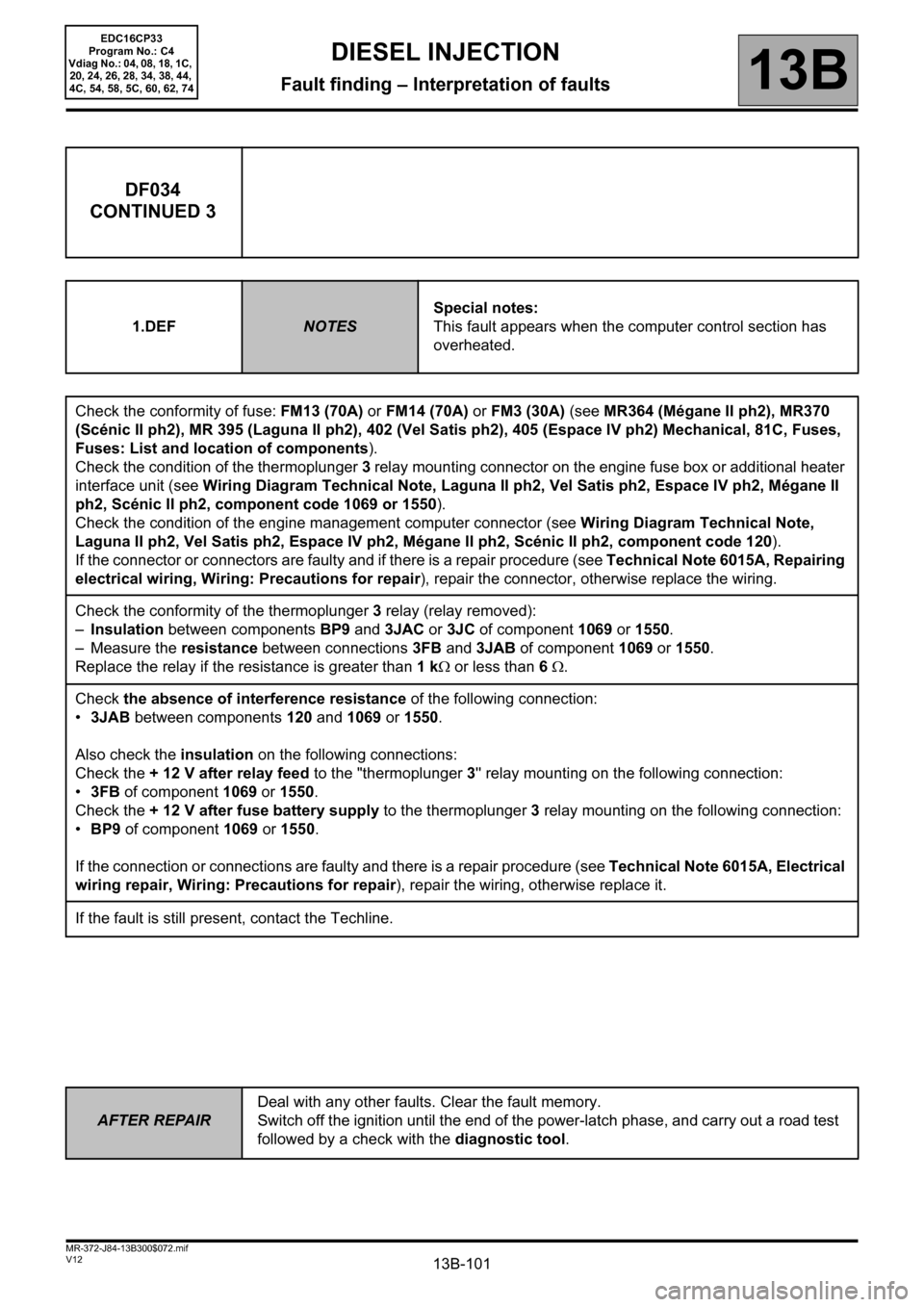
DF034
CONTINUED 3
1.DEFNOTESSpecial notes:
This fault appears when the computer control section has
overheated.
Check the conformity of fuse: FM13 (70A) or FM14 (70A) or FM3 (30A) (see MR364 (Mégane II ph2), MR370
(Scénic II ph2), MR 395 (Laguna II ph2), 402 (Vel Satis ph2), 405 (Espace IV ph2) Mechanical, 81C, Fuses,
Fuses: List and location of components).
Check the condition of the thermoplunger 3 relay mounting connector on the engine fuse box or additional heater
interface unit (see Wiring Diagram Technical Note, Laguna II ph2, Vel Satis ph2, Espace IV ph2, Mégane II
ph2, Scénic II ph2, component code 1069 or 1550).
Check the condition of the engine management computer connector (see Wiring Diagram Technical Note,
Laguna II ph2, Vel Satis ph2, Espace IV ph2, Mégane II ph2, Scénic II ph2, component code 120).
If the connector or connectors are faulty and if there is a repair procedure (see Technical Note 6015A, Repairing
electrical wiring, Wiring: Precautions for repair), repair the connector, otherwise replace the wiring.
Check the conformity of the thermoplunger 3 relay (relay removed):
–Insulation between components BP9 and 3JAC or 3JC of component 1069 or 1550.
– Measure the resistance between connections 3FB and 3JAB of component 1069 or 1550.
Replace the relay if the resistance is greater than 1 kΩ or less than 6 Ω.
Check the absence of interference resistance of the following connection:
•3JAB between components 120 and 1069 or 1550.
Also check the insulation on the following connections:
Check the + 12 V after relay feed to the "thermoplunger 3'' relay mounting on the following connection:
•3FB of component 1069 or
1550.
Check the + 12 V after fuse battery supply to the thermoplunger 3 relay mounting on the following connection:
•BP9 of component 1069 or 1550.
If the connection or connections are faulty and there is a repair procedure (see Technical Note 6015A, Electrical
wiring repair, Wiring: Precautions for repair), repair the wiring, otherwise replace it.
If the fault is still present, contact the Techline.
Page 114 of 510
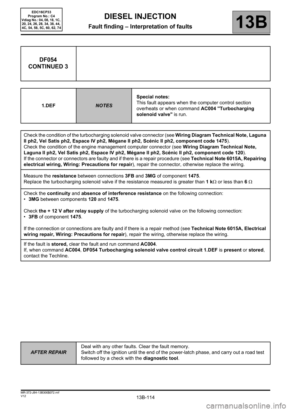
13B-114
AFTER REPAIRDeal with any other faults. Clear the fault memory.
Switch off the ignition until the end of the power-latch phase, and carry out a road test
followed by a check with the diagnostic tool.
V12 MR-372-J84-13B300$072.mif
DIESEL INJECTION
Fault finding – Interpretation of faults13B
EDC16CP33
Program No.: C4
Vdiag No.: 04, 08, 18, 1C,
20, 24, 26, 28, 34, 38, 44,
4C, 54, 58, 5C, 60, 62, 74
DF054
CONTINUED 3
1.DEFNOTESSpecial notes:
This fault appears when the computer control section
overheats or when command AC004 "Turbocharging
solenoid valve" is run.
Check the condition of the turbocharging solenoid valve connector (see Wiring Diagram Technical Note, Laguna
II ph2, Vel Satis ph2, Espace IV ph2, Mégane II ph2, Scénic II ph2, component code 1475).
Check the condition of the engine management computer connector (see Wiring Diagram Technical Note,
Laguna II ph2, Vel Satis ph2, Espace IV ph2, Mégane II ph2, Scénic II ph2, component code 120).
If the connector or connectors are faulty and if there is a repair procedure (see Technical Note 6015A, Repairing
electrical wiring, Wiring: Precautions for repair), repair the connector, otherwise replace the wiring.
Measure the resistance between connections3FB and 3MG of component1475.
Replace the turbocharging solenoid valve if the resistance measured is greater than 1 kΩ or less than 6 Ω
Check the continuity and absence of interference resistance on the following connection:
•3MG between components 120 and 1475.
Check the + 12 V after relay supply of the turbocharging solenoid valve on the following connection:
•3FB of component 1475.
If the connection or connections are faulty and if there is a repair method (see Technical Note 6015A, Electrical
wiring repair, Wiring: Precautions for repair), repair the wiring, otherwise replace the wiring.
If the fault is stored, clear the fault and run command AC004.
If, when command AC004, DF054 Turbocharging solenoid valve control circuit 1.DEF is present or stored,
contact the Techline.
Page 135 of 510
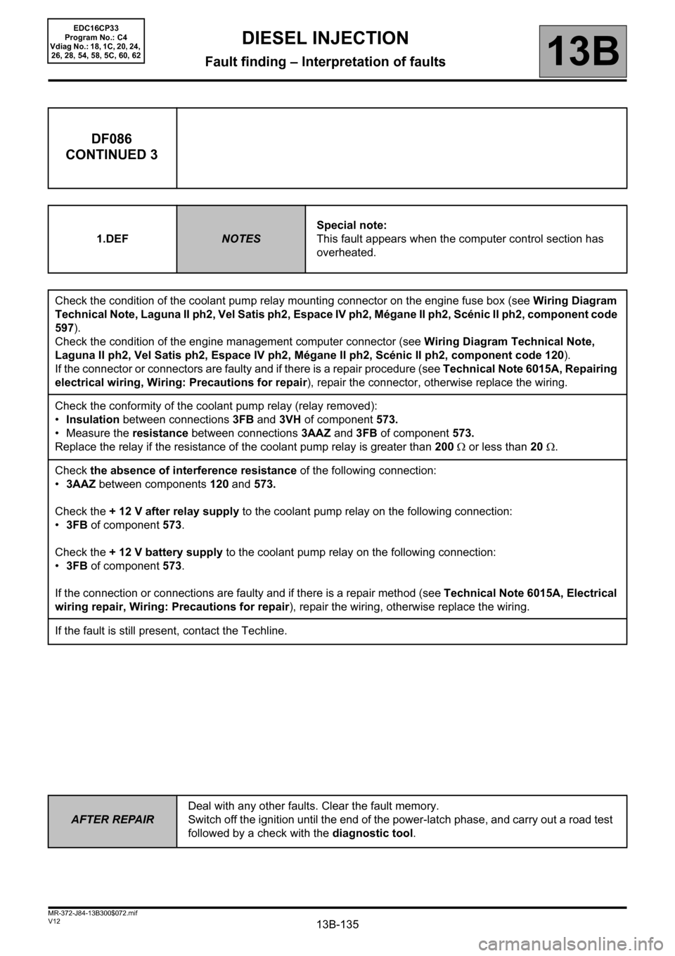
13B-135
AFTER REPAIRDeal with any other faults. Clear the fault memory.
Switch off the ignition until the end of the power-latch phase, and carry out a road test
followed by a check with the diagnostic tool.
V12 MR-372-J84-13B300$072.mif
DIESEL INJECTION
Fault finding – Interpretation of faults13B
EDC16CP33
Program No.: C4
Vdiag No.: 18, 1C, 20, 24,
26, 28, 54, 58, 5C, 60, 62
DF086
CONTINUED 3
1.DEFNOTESSpecial note:
This fault appears when the computer control section has
overheated.
Check the condition of the coolant pump relay mounting connector on the engine fuse box (see Wiring Diagram
Technical Note, Laguna II ph2, Vel Satis ph2, Espace IV ph2, Mégane II ph2, Scénic II ph2, component code
597).
Check the condition of the engine management computer connector (see Wiring Diagram Technical Note,
Laguna II ph2, Vel Satis ph2, Espace IV ph2, Mégane II ph2, Scénic II ph2, component code 120).
If the connector or connectors are faulty and if there is a repair procedure (see Technical Note 6015A, Repairing
electrical wiring, Wiring: Precautions for repair), repair the connector, otherwise replace the wiring.
Check the conformity of the coolant pump relay (relay removed):
•Insulation between connections 3FB and 3VH of component 573.
• Measure the resistance between connections 3AAZ and 3FB of component 573.
Replace the relay if the resistance of the coolant pump relay is greater than 200 Ω or less than 20 Ω.
Check the absence of interference resistance of the following connection:
•3AAZ between components 120 and 573.
Check the + 12 V after relay supply to the coolant pump relay on the following connection:
•3FB of component 573.
Check the + 12 V battery supply to the coolant pump relay on the following connection:
•3FB of component 573.
If the connection or connections are faulty and if there is a repair method (see Technical Note 6015A, Electrical
wiring repair, Wiring: Precautions for repair), repair the wiring, otherwise replace the wiring.
If the fault is still present, contact the Techline.