oil level RENAULT SCENIC 2012 J95 / 3.G Engine And Peripherals EDC16CP33 Workshop Manual
[x] Cancel search | Manufacturer: RENAULT, Model Year: 2012, Model line: SCENIC, Model: RENAULT SCENIC 2012 J95 / 3.GPages: 510, PDF Size: 2.98 MB
Page 63 of 510
13B-63
AFTER REPAIRDeal with any other faults. Clear the fault memory.
Switch off the ignition until the end of the power-latch phase, and carry out a road test
followed by a check with the diagnostic tool.
V12 MR-372-J84-13B300$071.mif
DIESEL INJECTION
Fault finding – Interpretation of faults13B
EDC16CP33
Program No.: C4
Vdiag No.: 04, 08, 18, 1C,
20, 24, 26, 28, 34, 38, 44,
4C, 54, 58, 5C, 60, 62, 74
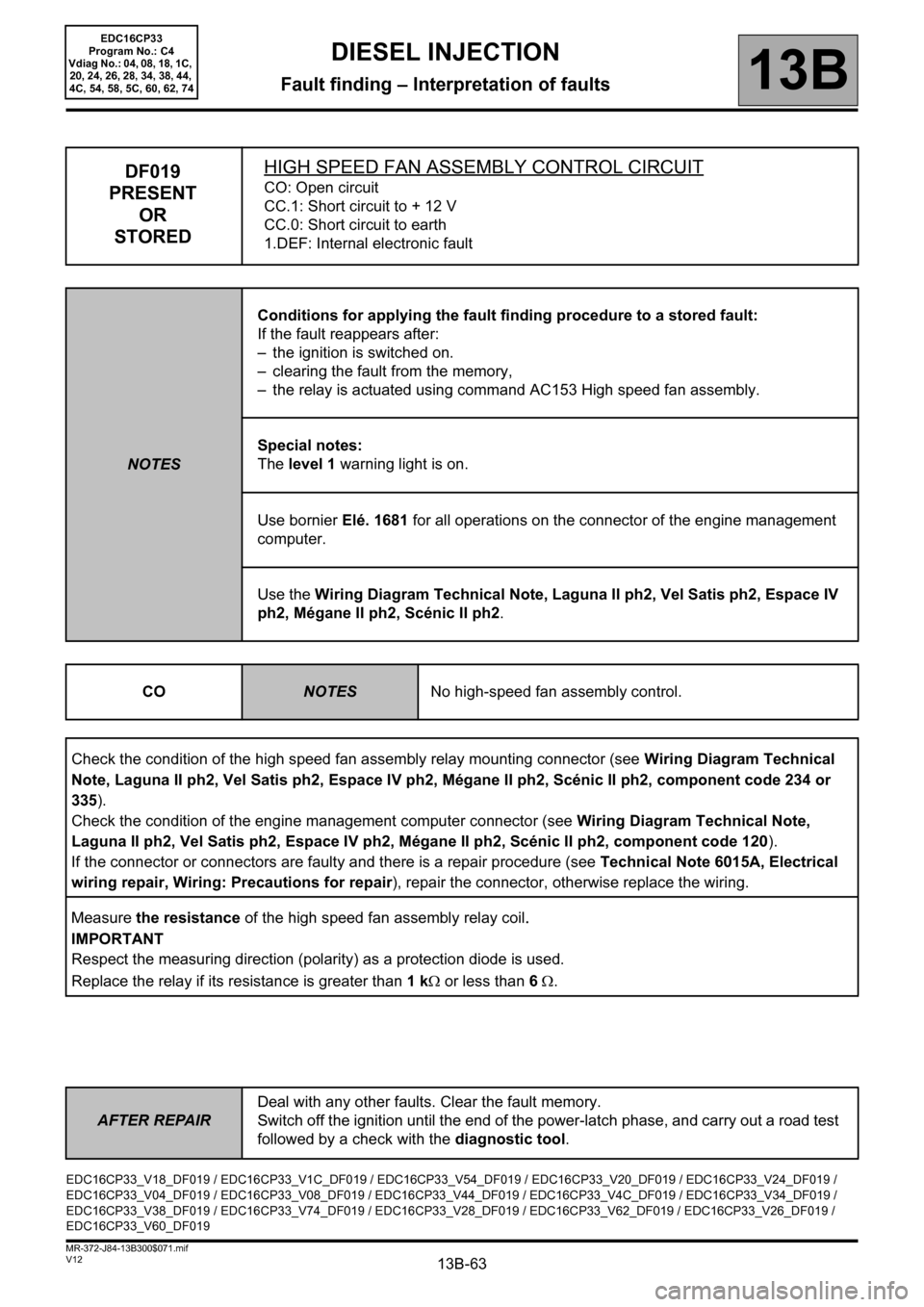
DF019
PRESENT
OR
STOREDHIGH SPEED FAN ASSEMBLY CONTROL CIRCUITCO: Open circuit
CC.1: Short circuit to + 12 V
CC.0: Short circuit to earth
1.DEF: Internal electronic fault
NOTESConditions for applying the fault finding procedure to a stored fault:
If the fault reappears after:
– the ignition is switched on.
– clearing the fault from the memory,
– the relay is actuated using command AC153 High speed fan assembly.
Special notes:
The level 1 warning light is on.
Use bornier Elé. 1681 for all operations on the connector of the engine management
computer.
Use the Wiring Diagram Technical Note, Laguna II ph2, Vel Satis ph2, Espace IV
ph2, Mégane II ph2, Scénic II ph2.
CO
NOTESNo high-speed fan assembly control.
Check the condition of the high speed fan assembly relay mounting connector (see
Wiring Diagram Technical
Note, Laguna II ph2, Vel Satis ph2, Espace IV ph2, Mégane II ph2, Scénic II ph2, component code 234 or
335).
Check the condition of the engine management computer connector (see Wiring Diagram Technical Note,
Laguna II ph2, Vel Satis ph2, Espace IV ph2, Mégane II ph2, Scénic II ph2, component code 120).
If the connector or connectors are faulty and there is a repair procedure (see Technical Note 6015A, Electrical
wiring repair, Wiring: Precautions for repair), repair the connector, otherwise replace the wiring.
Measure the resistance of the high speed fan assembly relay coil
.
IMPORTANT
Respect the measuring direction (polarity) as a protection diode is used.
Replace the relay if its resistance is greater than 1 kΩ or less than 6 Ω.
EDC16CP33_V18_DF019 / EDC16CP33_V1C_DF019 / EDC16CP33_V54_DF019 / EDC16CP33_V20_DF019 / EDC16CP33_V24_DF019 /
EDC16CP33_V04_DF019 / EDC16CP33_V08_DF019 / EDC16CP33_V44_DF019 / EDC16CP33_V4C_DF019 / EDC16CP33_V34_DF019 /
EDC16CP33_V38_DF019 / EDC16CP33_V74_DF019 / EDC16CP33_V28_DF019 / EDC16CP33_V62_DF019 / EDC16CP33_V26_DF019 /
EDC16CP33_V60_DF019
Page 139 of 510
13B-139
AFTER REPAIRDeal with any other faults. Clear the fault memory.
Switch off the ignition until the end of the power-latch phase, and carry out a road test
followed by a check with the diagnostic tool.
V12 MR-372-J84-13B300$072.mif
DIESEL INJECTION
Fault finding – Interpretation of faults13B
EDC16CP33
Program No.: C4
Vdiag No.: 04, 08, 18, 1C,
20, 24, 26, 28, 34, 38, 44,
4C, 54, 58, 5C, 60, 62, 74
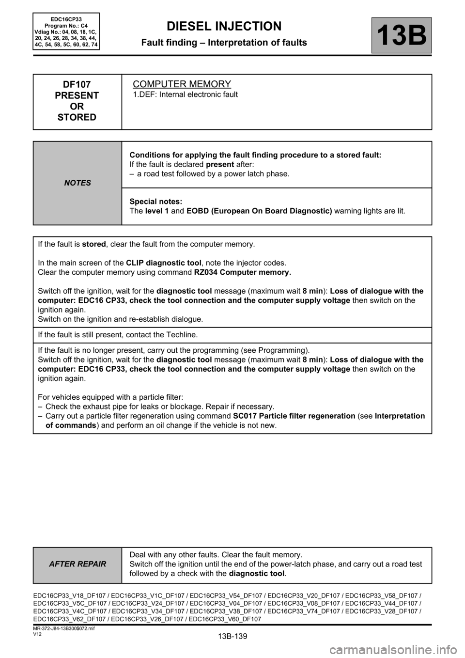
DF107
PRESENT
OR
STOREDCOMPUTER MEMORY
1.DEF: Internal electronic fault
NOTESConditions for applying the fault finding procedure to a stored fault:
If the fault is declared present after:
– a road test followed by a power latch phase.
Special notes:
The level 1 and EOBD (European On Board Diagnostic) warning lights are lit.
If the fault is stored, clear the fault from the computer memory.
In the main screen of the CLIP diagnostic tool, note the injector codes.
Clear the computer memory using command RZ034 Computer memory.
Switch off the ignition, wait for the diagnostic tool message (maximum wait 8 min): Loss of dialogue with the
computer: EDC16 CP33, check the tool connection and the computer supply voltage then switch on the
ignition again.
Switch on the ignition and re-establish dialogue.
If the fault is still present, contact the Techline.
If the fault is no longer present, carry out the programming (see Programming).
Switch off the ignition, wait for the diagnostic tool message (maximum wait 8 min): Loss of dialogue with the
computer: EDC16 CP33, check the tool connection and the computer supply voltage then switch on the
ignition again.
For vehicles equipped with a particle filter:
– Check the exhaust pipe for leaks or blockage. Repair if necessary.
– Carry out a particle filter regeneration using command SC017 Particle filter regeneration (see Interpretation
of commands) and perform an oil change if the vehicle is not new.
EDC16CP33_V18_DF107 / EDC16CP33_V1C_DF107 / EDC16CP33_V54_DF107 / EDC16CP33_V20_DF107 / EDC16CP33_V58_DF107 /
EDC16CP33_V5C_DF107 / EDC16CP33_V24_DF107 / EDC16CP33_V04_DF107 / EDC16CP33_V08_DF107 / EDC16CP33_V44_DF107 /
EDC16CP33_V4C_DF107 / EDC16CP33_V34_DF107 / EDC16CP33_V38_DF107 / EDC16CP33_V74_DF107 / EDC16CP33_V28_DF107 /
EDC16CP33_V62_DF107 / EDC16CP33_V26_DF107 / EDC16CP33_V60_DF107
Page 257 of 510
13B-257
AFTER REPAIRDeal with any other faults. Clear the fault memory.
Switch off the ignition until the end of the power-latch phase, and carry out a road test
followed by a check with the diagnostic tool.
V12 MR-372-J84-13B300$074.mif
DIESEL INJECTION
Fault finding – Interpretation of faults13B
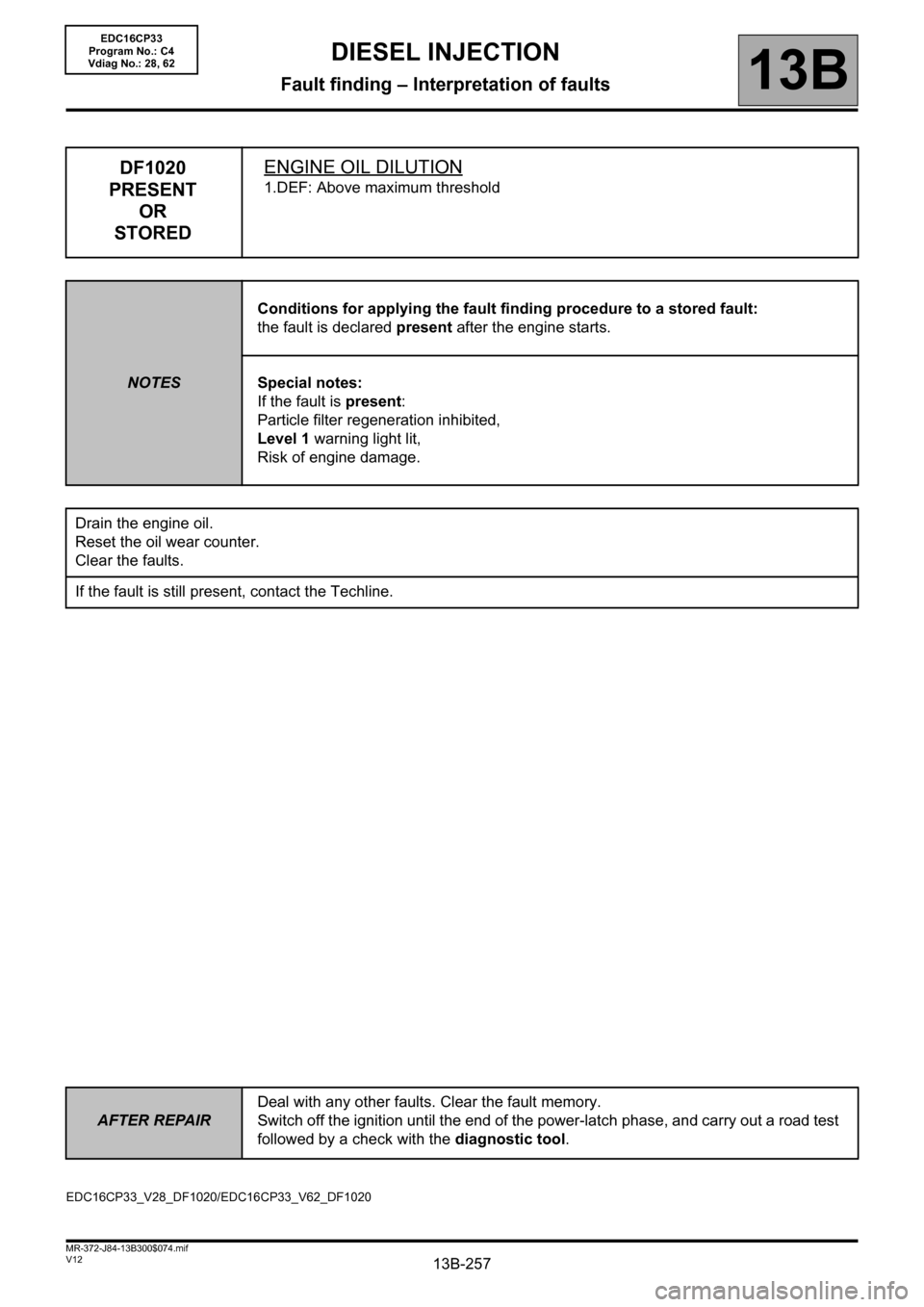
DF1020
PRESENT
OR
STOREDENGINE OIL DILUTION
1.DEF: Above maximum threshold
NOTESConditions for applying the fault finding procedure to a stored fault:
the fault is declared present after the engine starts.
Special notes:
If the fault is present:
Particle filter regeneration inhibited,
Level 1 warning light lit,
Risk of engine damage.
Drain the engine oil.
Reset the oil wear counter.
Clear the faults.
If the fault is still present, contact the Techline.
EDC16CP33_V28_DF1020/EDC16CP33_V62_DF1020
EDC16CP33
Program No.: C4
Vdiag No.: 28, 62
Page 420 of 510
13B-420
AFTER REPAIRCarry out a road test, then check with the diagnostic tool.
V12 MR-372-J84-13B300$130.mif
DIESEL INJECTION
Fault finding – Interpretation of parameters13B
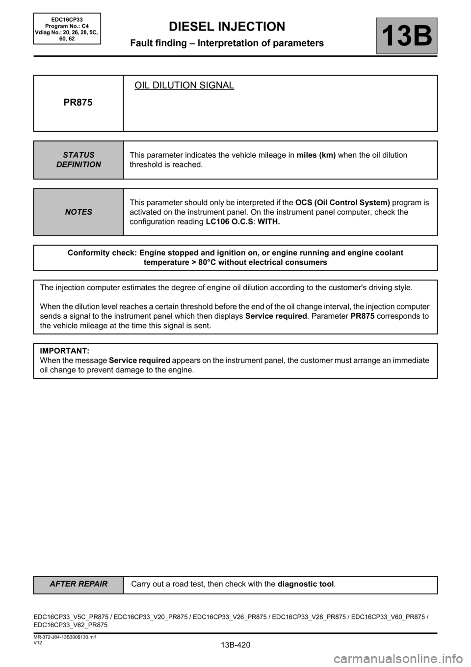
PR875OIL DILUTION SIGNAL
STATUS
DEFINITIONThis parameter indicates the vehicle mileage in miles (km) when the oil dilution
threshold is reached.
NOTESThis parameter should only be interpreted if the OCS (Oil Control System) program is
activated on the instrument panel. On the instrument panel computer, check the
configuration reading LC106 O.C.S: WITH.
Conformity check: Engine stopped and ignition on, or engine running and engine coolant
temperature > 80°C without electrical consumers
The injection computer estimates the degree of engine oil dilution according to the customer's driving style.
When the dilution level reaches a certain threshold before the end of the oil change interval, the injection computer
sends a signal to the instrument panel which then displays Service required. Parameter PR875 corresponds to
the vehicle mileage at the time this signal is sent.
IMPORTANT:
When the message Service required appears on the instrument panel, the customer must arrange an immediate
oil change to prevent damage to the engine.
EDC16CP33_V5C_PR875 / EDC16CP33_V20_PR875 / EDC16CP33_V26_PR875 / EDC16CP33_V28_PR875 / EDC16CP33_V60_PR875 /
EDC16CP33_V62_PR875
EDC16CP33
Program No.: C4
Vdiag No.: 20, 26, 28, 5C,
60, 62
Page 427 of 510
13B-427V12 MR-372-J84-13B300$150.mif
DIESEL INJECTION
Fault finding – Interpretation of commands13B
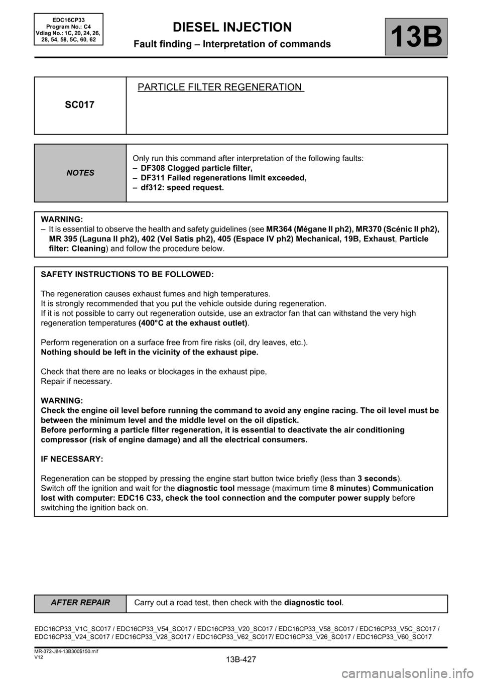
SC017PARTICLE FILTER REGENERATION
NOTESOnly run this command after interpretation of the following faults:
– DF308 Clogged particle filter,
– DF311 Failed regenerations limit exceeded,
– df312: speed request.
WARNING:
– It is essential to observe the health and safety guidelines (see MR364 (Mégane II ph2), MR370 (Scénic II ph2),
MR 395 (Laguna II ph2), 402 (Vel Satis ph2), 405 (Espace IV ph2) Mechanical, 19B, Exhaust, Particle
filter: Cleaning) and follow the procedure below.
SAFETY INSTRUCTIONS TO BE FOLLOWED:
The regeneration causes exhaust fumes and high temperatures.
It is strongly recommended that you put the vehicle outside during regeneration.
If it is not possible to carry out regeneration outside, use an extractor fan that can withstand the very high
regeneration temperatures (400°C at the exhaust outlet).
Perform regeneration on a surface free from fire risks (oil, dry leaves, etc.).
Nothing should be left in the vicinity of the exhaust pipe.
Check that there are no leaks or blockages in the exhaust pipe,
Repair if necessary.
WARNING:
Check the engine oil level before running the command to avoid any engine racing. The oil level must be
between the minimum level and the middle level on the oil dipstick.
Before performing a particle filter regeneration, it is essential to deactivate the air conditioning
compressor (risk of engine damage) and all the electrical consumers.
IF NECESSARY:
Regeneration can be stopped by pressing the engine start button twice briefly (less than 3 seconds).
Switch off the ignition and wait for the diagnostic tool message (maximum time 8 minutes) Communication
lost with computer: EDC16 C33, check the tool connection and the computer power supply before
switching the ignition back on.
EDC16CP33_V1C_SC017 / EDC16CP33_V54_SC017 / EDC16CP33_V20_SC017 / EDC16CP33_V58_SC017 / EDC16CP33_V5C_SC017 /
EDC16CP33_V24_SC017 / EDC16CP33_V28_SC017 / EDC16CP33_V62_SC017/ EDC16CP33_V26_SC017 / EDC16CP33_V60_SC017
EDC16CP33
Program No.: C4
Vdiag No.: 1C, 20, 24, 26,
28, 54, 58, 5C, 60, 62
AFTER REPAIRCarry out a road test, then check with the diagnostic tool.
Page 504 of 510
13B-504V12 MR-372-J84-13B300$180.mif
DIESEL INJECTION
Fault finding – Test13B
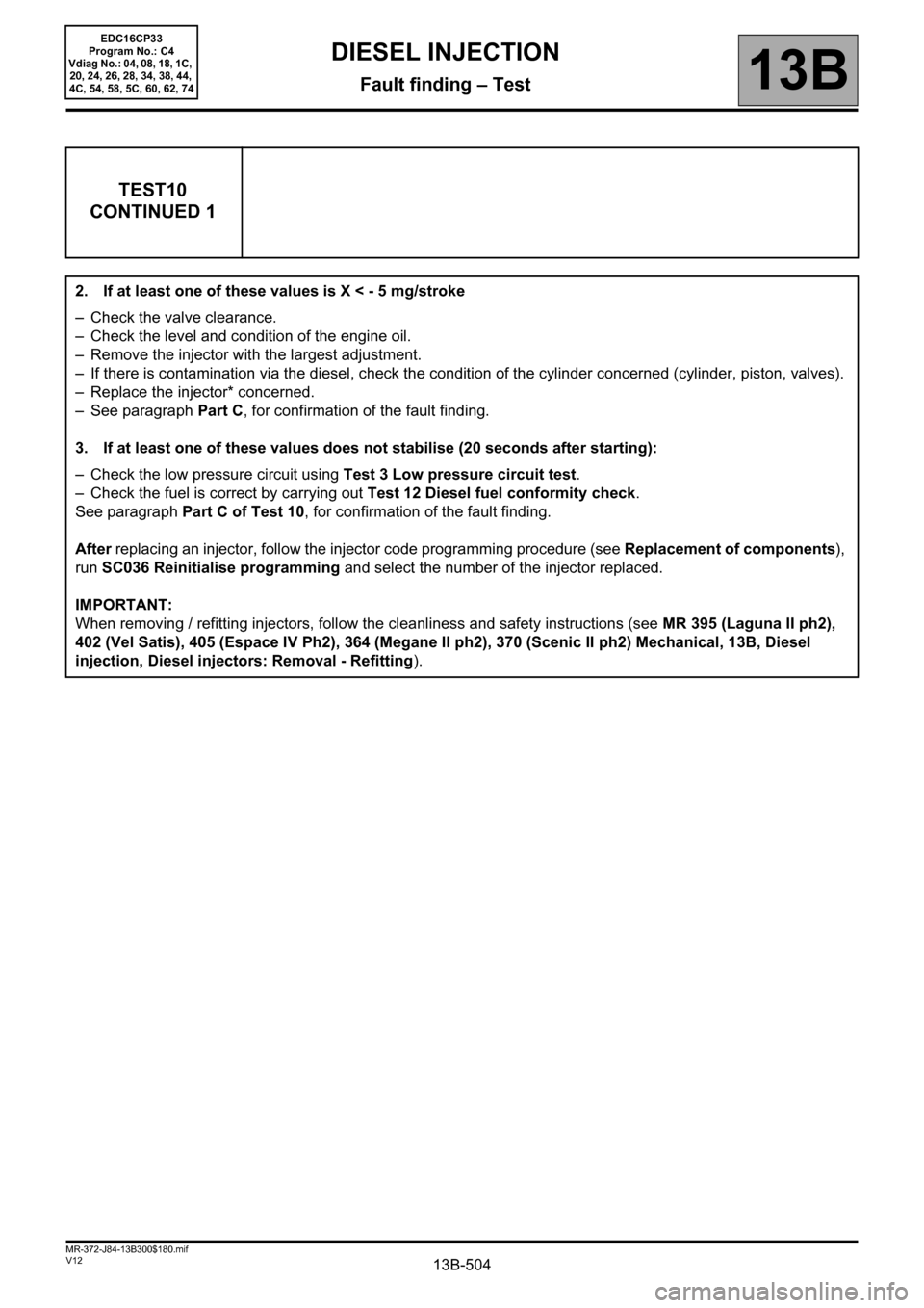
TEST10
CONTINUED 1
2. If at least one of these values is X < - 5 mg/stroke
– Check the valve clearance.
– Check the level and condition of the engine oil.
– Remove the injector with the largest adjustment.
– If there is contamination via the diesel, check the condition of the cylinder concerned (cylinder, piston, valves).
– Replace the injector* concerned.
– See paragraph Part C, for confirmation of the fault finding.
3. If at least one of these values does not stabilise (20 seconds after starting):
– Check the low pressure circuit using Test 3 Low pressure circuit test.
– Check the fuel is correct by carrying out Test 12 Diesel fuel conformity check.
See paragraph Part C of Test 10, for confirmation of the fault finding.
After replacing an injector, follow the injector code programming procedure (see Replacement of components),
run SC036 Reinitialise programming and select the number of the injector replaced.
IMPORTANT:
When removing / refitting injectors, follow the cleanliness and safety instructions (see MR 395 (Laguna II ph2),
402 (Vel Satis), 405 (Espace IV Ph2), 364 (Megane II ph2), 370 (Scenic II ph2) Mechanical, 13B, Diesel
injection, Diesel injectors: Removal - Refitting).
EDC16CP33
Program No.: C4
Vdiag No.: 04, 08, 18, 1C,
20, 24, 26, 28, 34, 38, 44,
4C, 54, 58, 5C, 60, 62, 74
Page 506 of 510
13B-506V12 MR-372-J84-13B300$180.mif
DIESEL INJECTION
Fault finding – Test13B
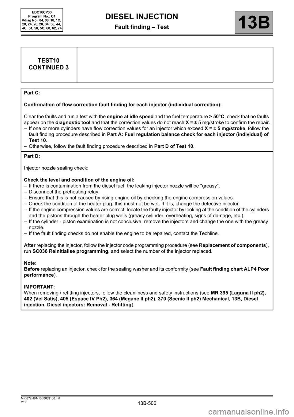
TEST10
CONTINUED 3
Part C:
Confirmation of flow correction fault finding for each injector (individual correction):
Clear the faults and run a test with the engine at idle speed and the fuel temperature > 50°C, check that no faults
appear on the diagnostic tool and that the correction values do not reach X = ± 5 mg/stroke to confirm the repair.
– If one or more cylinders have flow correction values for an injector which exceed X = ± 5 mg/stroke, follow the
fault finding procedure described in Part A: Fuel regulation balance check for each injector (individual) of
Test 10.
– Otherwise, follow the fault finding procedure described in Part D of Test 10.
Part D:
Injector nozzle sealing check:
Check the level and condition of the engine oil:
– If there is contamination from the diesel fuel, the leaking injector nozzle will be "greasy".
– Disconnect the preheating relay.
– Ensure that this is not caused by rising engine oil by checking the engine compression values.
– Check the condition of the heater plug: this must not be wet. If it is, change the defective injector.
– If the engine compression values are correct: locate the faulty injector by looking at the condition of the cylinders
and the pistons through the heater plug wells (greasy cylinder, overheating, signs of damage, etc.).
– If the cylinder - piston examination is not conclusive, remove the injectors and change the one with the greasy
nozzle.
– If the fault finding checks do not enable the engine to be repaired, contact the Techline.
After replacing the injector, follow the injector code programming procedure (see Replacement of components),
run SC036 Reinitialise programming, and select the number of the injector replaced.
Note:
Before replacing an injector, check for the sealing washer and its conformity (see Fault finding chart ALP4 Poor
performance).
IMPORTANT:
When removing / refitting injectors, follow the cleanliness and safety instructions (see MR 395 (Laguna II ph2),
402 (Vel Satis), 405 (Espace IV Ph2), 364 (Megane II ph2), 370 (Scenic II ph2) Mechanical, 13B, Diesel
injection, Diesel injectors: Removal - Refitting).
EDC16CP33
Program No.: C4
Vdiag No.: 04, 08, 18, 1C,
20, 24, 26, 28, 34, 38, 44,
4C, 54, 58, 5C, 60, 62, 74