Check anti RENAULT TALISMAN 2016 1.G Owners Manual
[x] Cancel search | Manufacturer: RENAULT, Model Year: 2016, Model line: TALISMAN, Model: RENAULT TALISMAN 2016 1.GPages: 328, PDF Size: 3.39 MB
Page 80 of 328
1.74
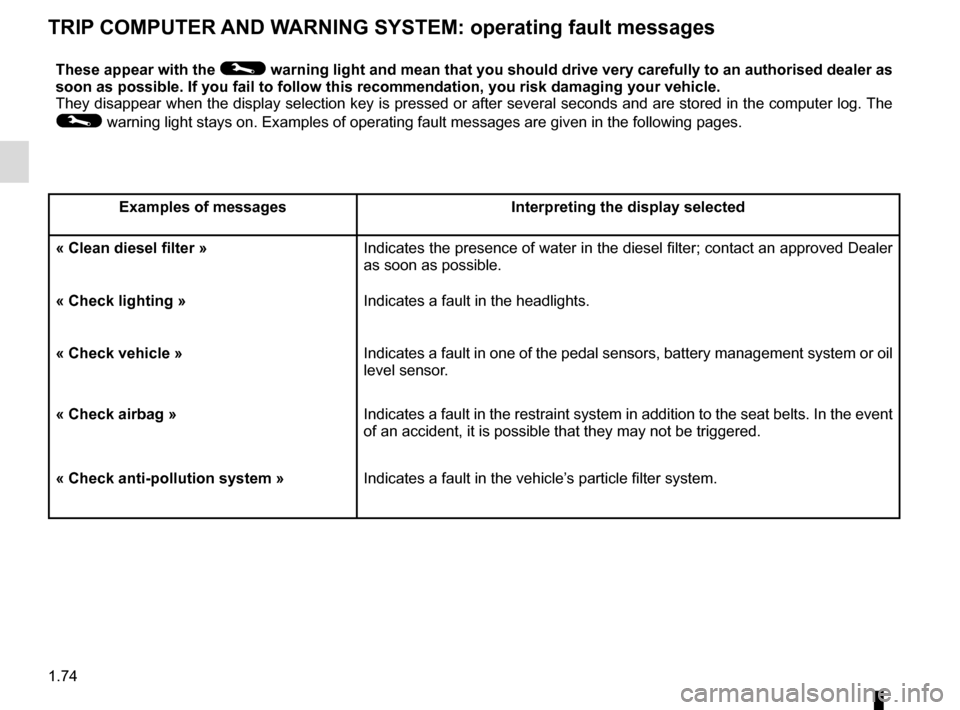
TRIP COMPUTER AND WARNING SYSTEM: operating fault messages
These appear with the © warning light and mean that you should drive very carefully to an author\
ised dealer as
soon as possible. If you fail to follow this recommendation, you risk da\
maging your vehicle.
They disappear when the display selection key is pressed or after severa\
l seconds and are stored in the computer log. The
© warning light stays on. Examples of operating fault messages are given \
in the following pages.
Examples of messages Interpreting the display selected
« Clean diesel filter » Indicates the presence of water in the diesel filter; contact an approve\
d Dealer
as soon as possible.
« Check lighting » Indicates a fault in the headlights.
« Check vehicle » Indicates a fault in one of the pedal sensors, battery management system\
or oil
level sensor.
« Check airbag » Indicates a fault in the restraint system in addition to the seat belts.\
In the event
of an accident, it is possible that they may not be triggered.
« Check anti-pollution system » Indicates a fault in the vehicle’s particle filter system.
Page 121 of 328
2.13
SPECIAL FEATURES OF DIESEL VERSIONS
Diesel engine speed
Diesel engines are fitted with an injec-
tion pump which prevents the engine
speed being exceeded irrespective of
the gear selected.
If the message “Check antipollution
system” is displayed along with warn-
ing lights
Ä and ©, consult an
authorised dealer immediately.
When driving, depending on the fuel
grade used, it is possible that white
smoke may be emitted.
This is due to the exhaust particle filter
being cleaned automatically, and does
not affect the way the vehicle runs.
Running out of fuel
If the tank has been completely
drained, the system must be reprimed
after the tank is refilled: see information
on the “fuel tank” in section 1 before re-
starting the engine.
Do not park the vehicle or
run the engine in locations
where combustible sub-
stances or materials such
as grass or leaves can come into
contact with the hot exhaust system.
Precautions to be taken in
winter
To avoid any faults in icy weather:
– ensure that the battery is always fully charged,
– always keep the diesel tank rela- tively full to avoid water vapour con-
densing in it and accumulating at the
bottom of the tank.
Page 131 of 328
2.23
MAINTENANCE AND ANTIPOLLUTION ADVICE
Your vehicle complies with criteria for
recycling and recovering vehicles at the
end of their service life which will come
into force in 2015.
Some parts of your vehicle have there-
fore been designed to facilitate future
recycling.
These parts are easy to remove so
that they can be recovered and reproc-
essed by recycling companies.
By virtue of its design, moderate fuel
consumption and initial settings, your
vehicle also conforms to current anti-
pollution regulations. The manufac-
turer is actively striving to reduce pol-
lutant exhaust gas emissions and to
save energy. But the fuel consumption
of your vehicle and the level of pollutant
exhaust gas emissions are also your
responsibility. Ensure that it is main-
tained and used correctly.
Maintenance
It is important to remember that fail-
ure to respect antipollution regulations
could lead to legal action being taken
against the vehicle owner.In addition, replacing engine, fuel
supply system and exhaust compo-
nents with parts other than those origi-
nally recommended by the manufac-
turer may alter your vehicle so that it
no longer complies with anti-pollution
regulations.
Have your vehicle adjusted and
checked by an authorised dealer, in ac-
cordance with the instructions given in
your maintenance schedule: they will
have all the equipment necessary for
ensuring that your vehicle is maintained
to its original standard.
Engine adjustments
– Spark plugs:
for optimum condi-
tions of use, output and performance
the specifications laid down by our
Design Department must be strictly
applied.
If the spark plugs have to be changed, use the make, type and gap specified
for your vehicle’s engine. Contact an
authorised dealer for this.
– Air filter, fuel filter: a choked ele-
ment will reduce efficiency. It must
be replaced.
– Ignition and idle speed: no adjust-
ment is needed.
Exhaust gas monitoring
system
The exhaust gas monitoring system will
detect any operating faults in the vehi-
cle’s antipollution system.
If this system malfunctions, toxic sub-
stances may be released into the at-
mosphere or damage may occur.
ÄThis warning light on the in-
strument panel will indicate if
there are any faults in the system:
This lights up when the ignition is
switched on and goes out when the
engine is started.
– If it lights up continuously, consult an approved Dealer as soon as possi-
ble;
– if it flashes, reduce the engine speed until the light stops flashing. Contact
an authorised dealer as soon as pos-
sible.
Page 140 of 328
2.32
DRIVER CORRECTION DEVICES AND AIDS (5/12)
Braking anticipation
Depending on the vehicle, when you
rapidly release the accelerator, the
system anticipates the braking ma-
noeuvre in order to reduce stopping
distances.
Special cases
When using the cruise control:
– if you use the accelerator, when you release it, the system may be trig-
gered;
– if you do not use the accelerator, the system will not be triggered.
Operating faults
When the system detects an operat-
ing fault the message “Check brak-
ing system” appears on the instrument
panel along with the
© warning
light.
Consult an approved dealer.
Emergency brake assist
This system supplements the ABS
and helps reduce vehicle stopping dis-
tances.
Operating principle
The system is for detecting an emer-
gency braking situation. In this case,
the braking assistance immediately de-
velops maximum power and may trig-
ger ABS regulation.
ABS braking is maintained as long as
the brake pedal is applied.
Hazard warning lights switching on
Depending on the vehicle, these may
light up in the event of sudden decel-
eration.
Page 210 of 328
3.20
ELECTRIC SUNROOF (2/3)Closing the sunroof by
remote control
(depending on the vehicle)
If you press the locking button on
the card twice in quick succession
RENAULT,, the windows and the elec-
tric sunroof will close automatically.
It is recommended that the user only
operates the system when the vehi-
cle can be seen clearly and no one is
inside.
Special features
Your vehicle is fitted with an anti-pinch
facility: when the sunroof encounters
resistance whilst closing (branch of
a tree, etc.), it stops and then moves
back a few centimetres.
After closing the sunroof by remote
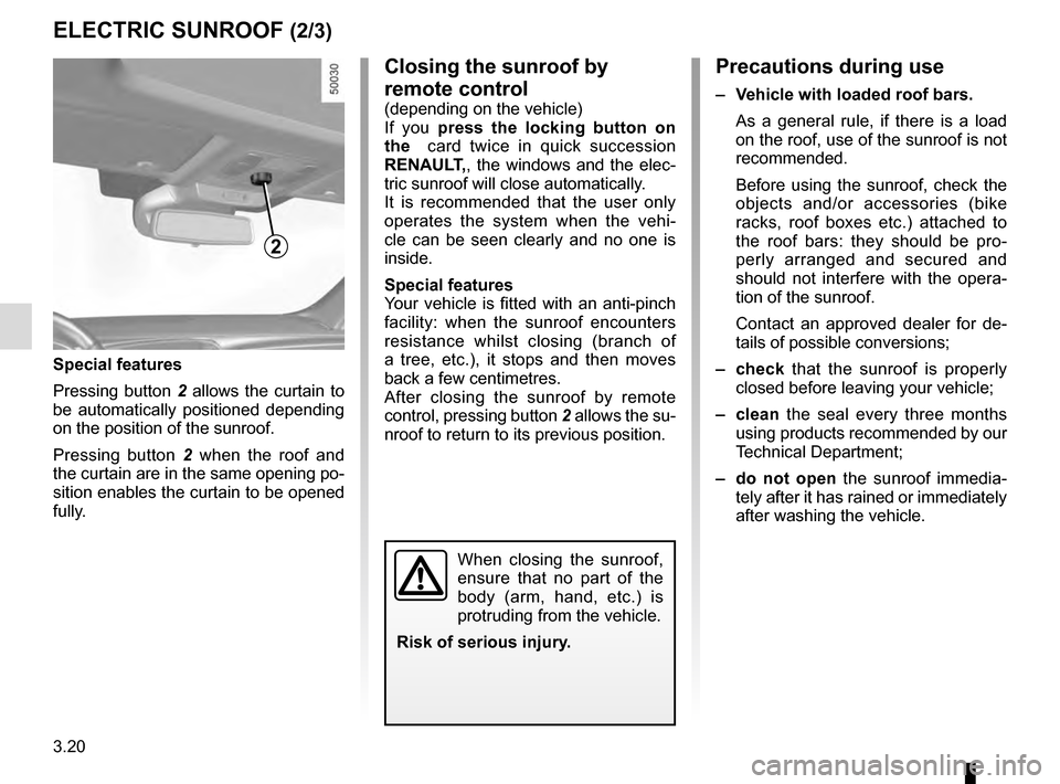
control, pressing button 2 allows the su-
nroof to return to its previous position.
Precautions during use
– Vehicle with loaded roof bars.
As a general rule, if there is a load
on the roof, use of the sunroof is not
recommended.
Before using the sunroof, check the
objects and/or accessories (bike
racks, roof boxes etc.) attached to
the roof bars: they should be pro-
perly arranged and secured and
should not interfere with the opera-
tion of the sunroof.
Contact an approved dealer for de-
tails of possible conversions;
– check that the sunroof is properly
closed before leaving your vehicle;
– clean the seal every three months using products recommended by our
Technical Department;
– do not open the sunroof immedia-
tely after it has rained or immediately
after washing the vehicle.
2
Special features
Pressing button 2 allows the curtain to
be automatically positioned depending
on the position of the sunroof.
Pressing button 2 when the roof and
the curtain are in the same opening po-
sition enables the curtain to be opened
fully.
When closing the sunroof,
ensure that no part of the
body (arm, hand, etc.) is
protruding from the vehicle.
Risk of serious injury.
Page 249 of 328
4.7
Replacement intervals
Refer to the Maintenance Document for
your vehicle.
Checking intervals
Check the coolant level regularly
(very severe damage is likely to be
caused to the engine if it runs out of
coolant).
If the level needs to be topped up, only
use products approved by our Technical
Department which ensure:
– protection against freezing;
– anticorrosion protection of the coo- ling system.
LEVELS (1/3)
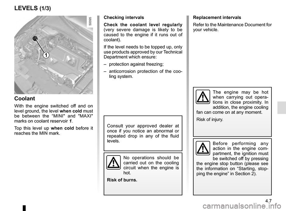
Coolant
With the engine switched off and on
level ground, the level when cold must
be between the “MINI" and "MAXI"
marks on coolant reservoir 1.
Top this level up when cold before it
reaches the MIN mark.
No operations should be
carried out on the cooling
circuit when the engine is
hot.
Risk of burns.
Consult your approved dealer at
once if you notice an abnormal or
repeated drop in any of the fluid
levels.
The engine may be hot
when carrying out opera-
tions in close proximity. In
addition, the engine cooling
fan can come on at any moment.
Risk of injury.
1
Before performing any
action in the engine com-
partment, the ignition must
be switched off by pressing
the engine stop button (please see
the information on “Starting, stop-
ping the engine” in Section 2).
Page 251 of 328
4.9
LEVELS (3/3)/FILTERS
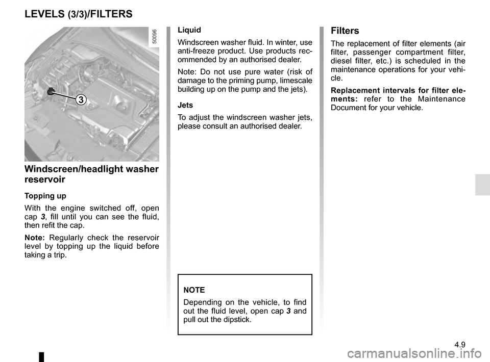
Windscreen/headlight washer
reservoir
Topping up
With the engine switched off, open
cap 3, fill until you can see the fluid,
then refit the cap.
Note: Regularly check the reservoir
level by topping up the liquid before
taking a trip. Liquid
Windscreen washer fluid. In winter, use
anti-freeze product. Use products rec-
ommended by an authorised dealer.
Note: Do not use pure water (risk of
damage to the priming pump, limescale
building up on the pump and the jets).
Jets
To adjust the windscreen washer jets,
please consult an authorised dealer.
NOTE
Depending on the vehicle, to find
out the fluid level, open cap
3 and
pull out the dipstick.
Filters
The replacement of filter elements (air
filter, passenger compartment filter,
diesel filter, etc.) is scheduled in the
maintenance operations for your vehi-
cle.
Replacement intervals for filter ele-
ments: refer to the Maintenance
Document for your vehicle.
3
Page 257 of 328
4.15
Respect local regulations about wash-
ing vehicles (e.g. do not wash your ve-
hicle on a public highway).
Observe the vehicle stopping distances
when driving on gravelled surfaces to
prevent paint damage.
Repair, or have repaired quickly, areas
where the paint has been damaged, to
prevent corrosion spreading.
Remember to visit the body shop pe-
riodically in order to maintain your
anti-corrosion warranty. Refer to the
Maintenance Document.
If it is necessary to clean mechani-
cal components, hinges, etc., spray
them with products approved by our
Technical Department to protect them
after they have been cleaned.
BODYWORK MAINTENANCE (2/2)
We have selected special products
to care for your vehicle and you can
obtain these from the manufactur-
er’s accessory outlets.
Using a roller type car wash
Return the windscreen wiper stalk to
the Park position (refer to the informa-
tion on the “Windscreen washer, wiper”
in Section 1). Check the mounting of
external accessories, additional lights
and mirrors, and ensure that the wiper
blades are secured with adhesive tape.
Remove the radio aerial mast if your
vehicle is fitted with this equipment.
Remember to remove the tape and refit
the antenna after washing.
Cleaning the headlights
As the headlights are made of plastic
“glass”, use a soft cloth or cotton wool
to clean them. If this does not clean
them properly, moisten the cloth with
soapy water, then wipe clean with a soft
damp cloth or cotton wool.
Finally, carefully dry off with a soft dry
cloth.
Cleaning products containing alco-
hol must not be used.
Vehicles with a matte paint
finish
This type of paint requires certain pre-
cautions.
Do not do the following
– use wax-based products (polishing);
– rub hard;
– wash the vehicle in a roller-type car
wash;
– wash the vehicle using a high-pres-
sure device;
– attach stickers to the paintwork (risk
of leaving marks).
You should do the following
Wash the vehicle by hand using plenty
of water, using a soft cloth or a gentle
sponge.
Page 262 of 328
5.2
PUNCTURE, EMERGENCY SPARE WHEEL
If the vehicle is parked on
the hard shoulder, you must
warn other road users of
your vehicle’s presence
with a warning triangle or with other
devices as per the legislation apply-
ing to the country you are in.
Special note
The Tyre Pressure Monitor function
does not check the emergency spare
wheel (the wheel replaced by the emer-
gency spare wheel disappears from the
instrument panel display).
Refer to the information on the “Tyre
pressure monitoring system” in
Section 2.Emergency spare wheel
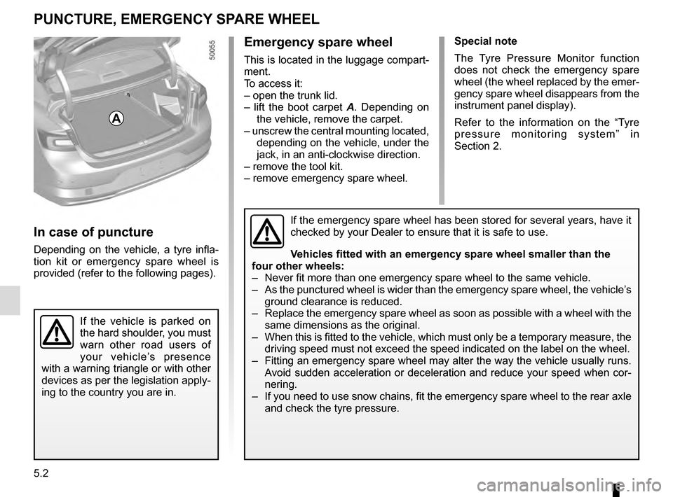
This is located in the luggage compart-
ment.
To access it:
– open the trunk lid.
– lift the boot carpet A . Depending on
the vehicle, remove the carpet.
– unscrew the central mounting located, depending on the vehicle, under the
jack, in an anti-clockwise direction.
– remove the tool kit.
– remove emergency spare wheel.
If the emergency spare wheel has been stored for several years, have it \
checked by your Dealer to ensure that it is safe to use.
Vehicles fitted with an emergency spare wheel smaller than the
four other wheels:
– Never fit more than one emergency spare wheel to the same vehicle.
– As the punctured wheel is wider than the emergency spare wheel, the vehi\
cle’s ground clearance is reduced.
– Replace the emergency spare wheel as soon as possible with a wheel with \
the same dimensions as the original.
– When this is fitted to the vehicle, which must only be a temporary measu\
re, the driving speed must not exceed the speed indicated on the label on the wh\
eel.
– Fitting an emergency spare wheel may alter the way the vehicle usually r\
uns. Avoid sudden acceleration or deceleration and reduce your speed when cor-\
nering.
– If you need to use snow chains, fit the emergency spare wheel to the rea\
r axle and check the tyre pressure.
A
In case of puncture
Depending on the vehicle, a tyre infla-
tion kit or emergency spare wheel is
provided (refer to the following pages).
Page 268 of 328

5.8
TOOLS (2/2)/WHEEL TRIM
A
BC
D
Wheel trim
Remove using the hubcap tool 6 by
connecting the hook in the recess pro-
vided next to the valve 8 (to secure the
metal clip).
To refit the wheel trim, align it with
valve 8. Push the retaining hooks in
fully, starting with side A near the valve,
followed by B and C, finishing at D op-
posite the valve.
Note: if you are using anti-theft bolts,
refer to the information on “Changing a
wheel”.
Do not leave the tools un-
secured inside the vehicle
as they may come loose
under braking. After use,
check that all the tools are correctly
clipped into the tool kit, then posi-
tion it correctly in its housing: risk of
injury.
If wheel bolts are supplied in the
tool kit, only use these bolts for the
emergency spare wheel: refer to the
label affixed to the emergency spare
wheel.
The jack is designed for wheel
changing purposes only. Under no
circumstances should it be used for
carrying out repairs underneath the
vehicle or to gain access to the un-
derside of the vehicle.
6
8