tow RENAULT TRAFIC 2015 X82 / 3.G User Guide
[x] Cancel search | Manufacturer: RENAULT, Model Year: 2015, Model line: TRAFIC, Model: RENAULT TRAFIC 2015 X82 / 3.GPages: 292, PDF Size: 6.66 MB
Page 168 of 292
3.6
MANUAL AIR CONDITIONING (3/4)
Distribution of air in the
passenger compartment
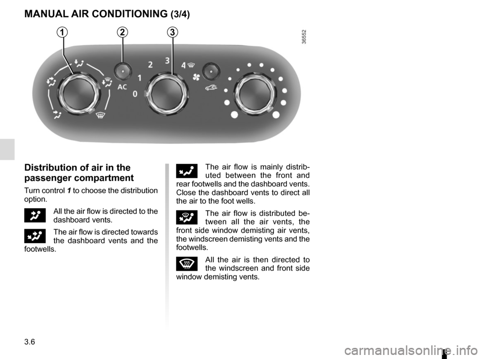
Turn control 1 to choose the distribution
option.
JAll the air flow is directed to the
dashboard vents.
GThe air flow is directed towards
the dashboard vents and the
footwells.
FThe air flow is mainly distrib-
uted between the front and
rear footwells and the dashboard vents.
Close the dashboard vents to direct all
the air to the foot wells.
iThe air flow is distributed be-
tween all the air vents, the
front side window demisting air vents,
the windscreen demisting vents and the
footwells.
WAll the air is then directed to
the windscreen and front side
window demisting vents.
321
Page 171 of 292
3.9
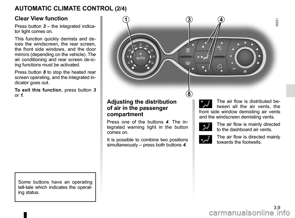
Clear View function
Press button 3 – the integrated indica-
tor light comes on.
This function quickly demists and de-
ices the windscreen, the rear screen,
the front side windows, and the door
mirrors (depending on the vehicle). The
air conditioning and rear screen de-ic-
ing functions must be activated.
Press button 8 to stop the heated rear
screen operating, and the integrated in-
dicator goes out.
To exit this function, press button 3
or 1.
AUTOMATIC CLIMATE CONTROL (2/4)
ØThe air flow is distributed be-
tween all the air vents, the
front side window demisting air vents
and the windscreen demisting vents.
½The air flow is mainly directed
to the dashboard air vents.
¿The air flow is directed mainly
towards the footwells.
Adjusting the distribution
of air in the passenger
compartment
Press one of the buttons 4 . The in-
tegrated warning light in the button
comes on.
It is possible to combine two positions
simultaneously – press both buttons 4.
8
3
Some buttons have an operating
tell-tale which indicates the operat-
ing status.
14
Page 174 of 292
3.12
Operating faults
As a general rule, contact your ap-
proved dealer in the event of an oper-
ating fault.
– Reduction in de-icing, demisting or air conditioning performance.
This may be caused by the passen-
ger compartment filter cartridge be-
coming clogged.
– No cold air is being produced .
Check that the controls are set cor-
rectly and that the fuses are sound.
Otherwise, switch off the system.
Presence of water under the
vehicle
After prolonged use of the air condi-
tioning system, it is normal for water
to be present under the vehicle. This is
caused by condensation.
AIR CONDITIONING: information and advice on use
Do not open the refriger-
ant fluid circuit. The fluid
may damage eyes or skin.
Fuel consumption
You will normally notice an increase in
fuel consumption (especially in town)
when the air conditioning is operating.
Advice for reducing consumption
and helping to preserve the environ-
ment
Switch off the system when it is not re-
quired.
Drive with the air vents open and the
windows closed.
If the vehicle has been parked in the
sun, open the doors for a few moments
to let the hot air escape before starting
the engine.
Vehicles fitted with an
auxiliary heater
Some vehicles are fitted with an auxil-
iary heater which heats the passenger
compartment more quickly.
This device operates only when the
engine is running and in cold weather.
When the device is functioning you
can normally see a small amount of
smoke on the right-hand side of the ve-
hicle coming from the heater’s exhaust
system.
Advice on useIn some situations, (air conditioning
off, air recirculation activated, ventila-
tion speed at zero or low, etc.) you may
notice that condensation starts to form
on the windows and windscreen.
If there is condensation, use the “Clear
View” function to remove it, then use
the air conditioning in automatic mode
to stop it forming again.
MaintenanceRefer to the Maintenance Document
for your vehicle for the inspection fre-
quency.
Do not add anything to the
vehicle’s ventilation circuit
(for example, to remove
bad odours).
There is a risk of damage or of
fire.
Fuel consumption increases when
the air conditioning is being used
(switch it off when it is not required).
Page 183 of 292
3.21
PASSENGER COMPARTMENT STORAGE/FITTINGS (3/9)
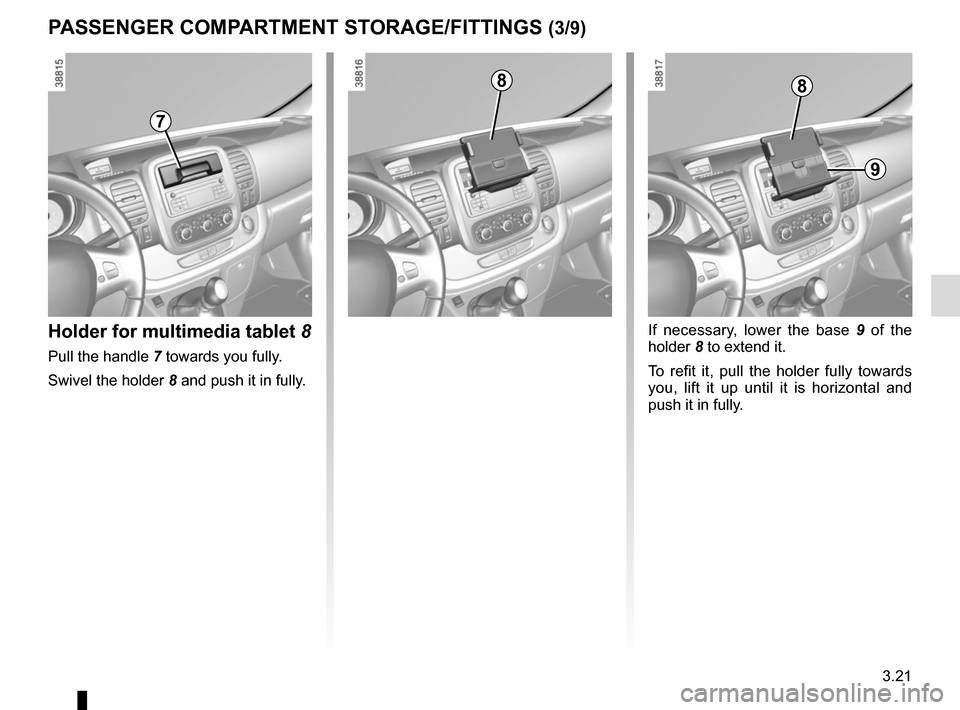
Holder for multimedia tablet 8
Pull the handle 7 towards you fully.
Swivel the holder 8 and push it in fully.
If necessary, lower the base 9 of the
holder 8 to extend it.
To refit it, pull the holder fully towards
you, lift it up until it is horizontal and
push it in fully.
7
88
9
Page 189 of 292
3.27
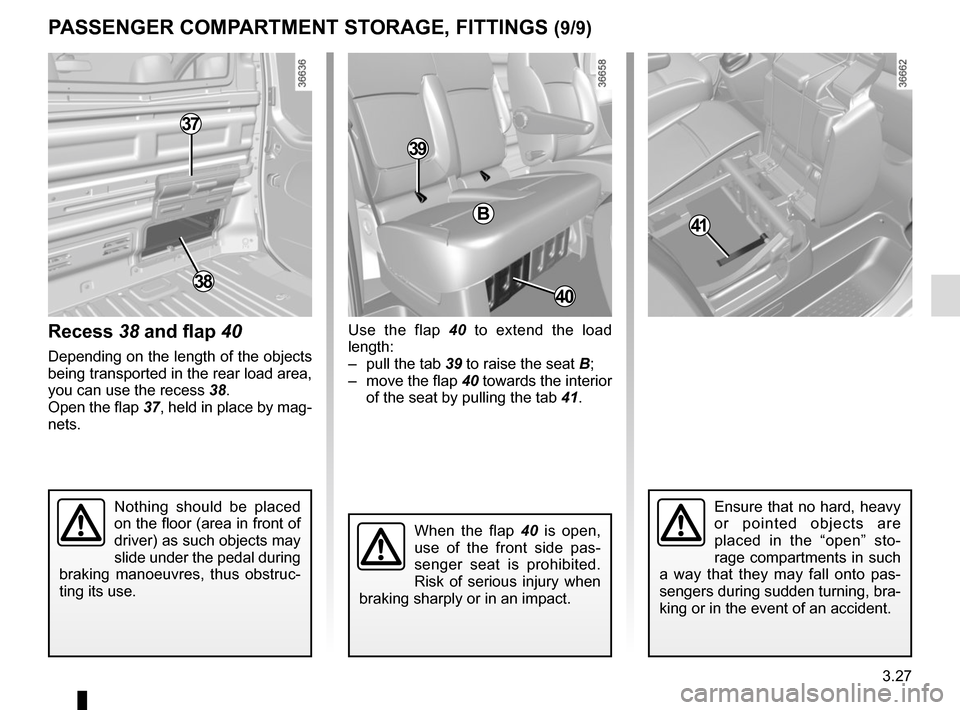
Use the flap 40 to extend the load
length:
– pull the tab 39 to raise the seat B;
– move the flap 40 towards the interior of the seat by pulling the tab 41.
PASSENGER COMPARTMENT STORAGE, FITTINGS (9/9)
37
Recess 38 and flap 40
Depending on the length of the objects
being transported in the rear load area,
you can use the recess 38.
Open the flap 37, held in place by mag-
nets.
40
B41
Nothing should be placed
on the floor (area in front of
driver) as such objects may
slide under the pedal during
braking manoeuvres, thus obstruc-
ting its use.Ensure that no hard, heavy
or pointed objects are
placed in the “open” sto-
rage compartments in such
a way that they may fall onto pas-
sengers during sudden turning, bra-
king or in the event of an accident.
38
39
When the flap 40 is open,
use of the front side pas-
senger seat is prohibited.
Risk of serious injury when
braking sharply or in an impact.
Page 195 of 292
3.33
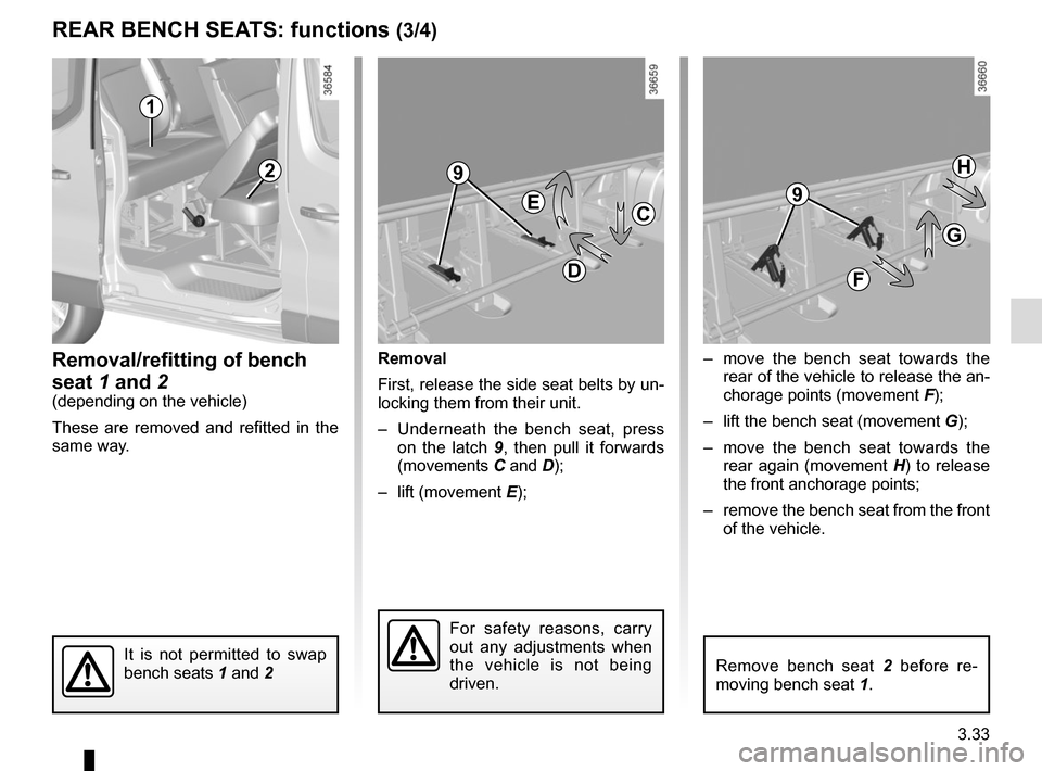
– move the bench seat towards the rear of the vehicle to release the an-
chorage points (movement F);
– lift the bench seat (movement G);
– move the bench seat towards the rear again (movement H) to release
the front anchorage points;
– remove the bench seat from the front of the vehicle.
REAR BENCH SEATS: functions (3/4)
Removal/refitting of bench
seat 1 and 2
(depending on the vehicle)
These are removed and refitted in the
same way. Removal
First, release the side seat belts by un-
locking them from their unit.
– Underneath the bench seat, press
on the latch 9, then pull it forwards
(movements C and D);
– lift (movement E);
It is not permitted to swap
bench seats 1 and 2
1
2
C
D
E
F
G
H
For safety reasons, carry
out any adjustments when
the vehicle is not being
driven.
Remove bench seat 2 before re-
moving bench seat 1.
9
9
Page 202 of 292
3.40
TRANSPORTING OBJECTS towbar
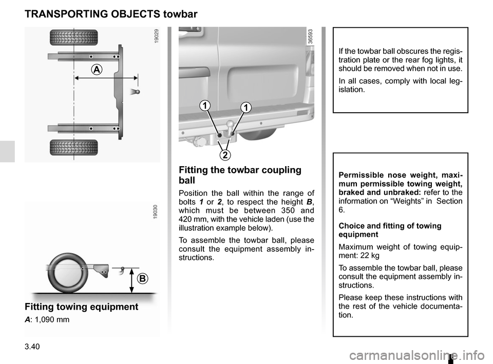
Fitting the towbar coupling
ball
Position the ball within the range of
bolts 1 or 2 , to respect the height B,
which must be between 350 and
420 mm, with the vehicle laden (use the
illustration example below).
To assemble the towbar ball, please
consult the equipment assembly in-
structions.
A
If the towbar ball obscures the regis-
tration plate or the rear fog lights, it
should be removed when not in use.
In all cases, comply with local leg-
islation.
Permissible nose weight, maxi-
mum permissible towing weight,
braked and unbraked: refer to the
information on “Weights” in Section
6.
Choice and fitting of towing
equipment
Maximum weight of towing equip-
ment: 22 kg
To assemble the towbar ball, please
consult the equipment assembly in-
structions.
Please keep these instructions with
the rest of the vehicle documenta-
tion.
2
B
11
Fitting towing equipment
A: 1,090 mm
Page 215 of 292
4.11
Tyre safety and use of snow
chains
Refer to the information on “Tyres”
in Section 5 for the servicing con-
ditions and, depending on the ver-
sion, the use of chains.
Special note
For vehicles used fully laden
(maximum permissible all-up
weight) and towing a trailer. The
maximum speed must be limited
to 60 mph (100 km/h) and the tyre
pressure increased by 0.2 bar.
Refer to the information on “Weights”
in Section 6.
TYRE PRESSURE (2/2)
C
DE
B
A
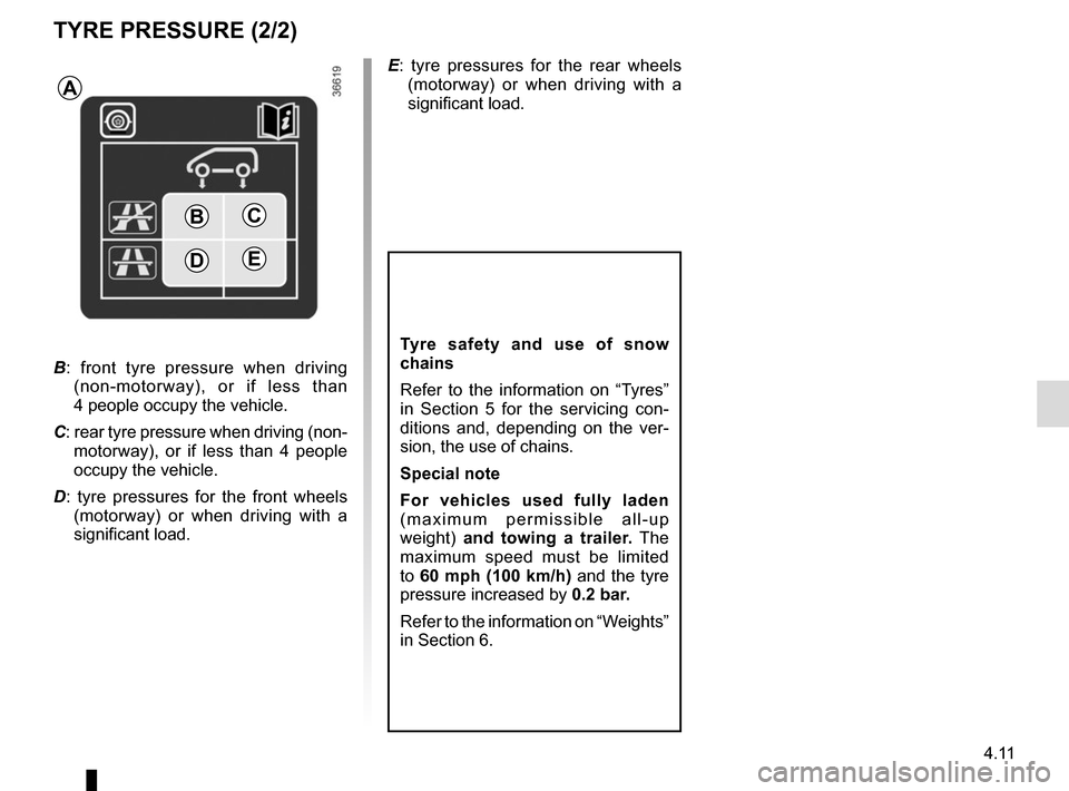
B : front tyre pressure when driving
(non-motorway), or if less than
4 people occupy the vehicle.
C: rear tyre pressure when driving (non- motorway), or if less than 4 people
occupy the vehicle.
D : tyre pressures for the front wheels
(motorway) or when driving with a
significant load. E
: tyre pressures for the rear wheels
(motorway) or when driving with a
significant load.
Page 221 of 292
5.1
Section 5: Practical advice
Puncture, emergency spare wheel . . . . . . . . . . . . . . . . . . . . . . . . . . . . . . . . . . . .\
. . . . . . . . . . . . . . 5.2
Tyre inflation kit . . . . . . . . . . . . . . . . . . . . . . . . . . . \
. . . . . . . . . . . . . . . . . . . . . . . . . . . . . . . . . . . . . . 5.4
Tools . . . . . . . . . . . . . . . . . . . . . . . . . . . . . . . . . . . .\
. . . . . . . . . . . . . . . . . . . . . . . . . . . . . . . . . . . . . 5.7
Wheel trims . . . . . . . . . . . . . . . . . . . . . . . . . . . . . . \
. . . . . . . . . . . . . . . . . . . . . . . . . . . . . . . . . . . . . . 5.8
Changing a wheel . . . . . . . . . . . . . . . . . . . . . . . . . . . . . . . . . . . .\
. . . . . . . . . . . . . . . . . . . . . . . . . . . 5.9
Tyres (tyre and wheel safety, use in winter) . . . . . . . . . . . . . . . . . . . . . . . . . . . . . . . . . . . .\
. . . . . . . 5.11
Headlights (changing bulbs) . . . . . . . . . . . . . . . . . . . . . . . . . . . . . . . . . . . .\
. . . . . . . . . . . . . . . . . . . 5.14
Side lights . . . . . . . . . . . . . . . . . . . . . . . . . . . . . . . . . . . .\
. . . . . . . . . . . . . . . . . . . . . . . . . . . . . . . . . 5.15
Rear lights (changing bulbs) . . . . . . . . . . . . . . . . . . . . . . . . . . . . . . . . . . . .\
. . . . . . . . . . . . . . . . . . . 5.16
Indicator lights (changing bulbs) . . . . . . . . . . . . . . . . . . . . . . . . . . . . . . . . . . . .\
. . . . . . . . . . . . . . . . 5.19
Interior lighting (changing bulbs) . . . . . . . . . . . . . . . . . . . . . . . . . . . . . . . . . . . . \
. . . . . . . . . . . . . . . . 5.20
Key, radio frequency remote control: battery . . . . . . . . . . . . . . . . . . . . . . . . . . . . . . . . . . . . \
. . . . . . . 5.22
RENAULT card: battery . . . . . . . . . . . . . . . . . . . . . . . . . . . . . . . . . . . . \
. . . . . . . . . . . . . . . . . . . . . . . 5.23
Battery . . . . . . . . . . . . . . . . . . . . . . . . . . . . . . . . . . . . \
. . . . . . . . . . . . . . . . . . . . . . . . . . . . . . . . . . . . 5.24
Fitting a radio . . . . . . . . . . . . . . . . . . . . . . . . . . . . . . . . . . . . \
. . . . . . . . . . . . . . . . . . . . . . . . . . . . . . . 5.26
Fuses . . . . . . . . . . . . . . . . . . . . . . . . . . . . . . . . . . . . \
. . . . . . . . . . . . . . . . . . . . . . . . . . . . . . . . . . . . . 5.27
Accessories . . . . . . . . . . . . . . . . . . . . . . . . . . . . . . . . . . . . \
. . . . . . . . . . . . . . . . . . . . . . . . . . . . . . . . 5.30
Wipers (replacing blades) . . . . . . . . . . . . . . . . . . . . . . . . . . . . . . . . . . . .\
. . . . . . . . . . . . . . . . . . . . . 5.31
Towing . . . . . . . . . . . . . . . . . . . . . . . . . . . . . . . . . . . . \
. . . . . . . . . . . . . . . . . . . . . . . . . . . . . . . . . . . . 5.33
Operating faults . . . . . . . . . . . . . . . . . . . . . . . . . . . . . . . . . . . . \
. . . . . . . . . . . . . . . . . . . . . . . . . . . . . 5.35
Page 223 of 292
5.3
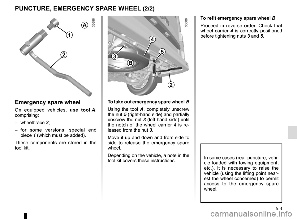
To refit emergency spare wheel B
Proceed in reverse order. Check that
wheel carrier 4 is correctly positioned
before tightening nuts 3 and 5.
PUNCTURE, EMERGENCY SPARE WHEEL (2/2)
Emergency spare wheel
On equipped vehicles, use tool A,
comprising:
– wheelbrace 2;
– for some versions, special end piece 1 (which must be added).
These components are stored in the
tool kit. To take out emergency spare wheel B
Using the tool A
, completely unscrew
the nut 5 (right-hand side) and partially
unscrew the nut 3 (left-hand side) until
the notch of the wheel carrier 4 is re-
leased from the nut 3.
Move it up and down and from side to
side to release the emergency spare
wheel.
Depending on the vehicle, a note in the
tool kit covers these instructions.
In some cases (rear puncture, vehi-
cle loaded with towing equipment,
etc.), it is necessary to raise the
vehicle (using the lifting point near-
est the wheel concerned) to permit
access to the emergency spare
wheel.
A
4
3
B
5
1
2
2