radio RENAULT TWINGO 2009 2.G Electrical Equipment - Multiplexing Workshop Manual
[x] Cancel search | Manufacturer: RENAULT, Model Year: 2009, Model line: TWINGO, Model: RENAULT TWINGO 2009 2.GPages: 33, PDF Size: 0.18 MB
Page 2 of 33
88B-2V3 MR-413-X44-88B000$010.mif
88B
INTRODUCTION
Description of the multiplex network:
The multiplex network consists of a twisted pair of wires connected to several vehicle computers.
These two wires are called multiplex line H and multiplex line L.
Depending on the vehicle options, there is a single multiplex network.
–the Vehicle multiplex line (injection, anti-lock braking system/electronic stability program, instrument panel, air
conditioning, rev counter, sequential gearbox, UCH, airbag/pretensioners) is always present,
–the Multimedia multiplex line (navigation, radio, display, hands-free telephone) depending on the vehicle options.
Data is exchanged by the computers on the Vehicle multiplex line and Multimedia multiplex line networks at a
communication speed of 500 kbit/s.
The Vehicle multiplex line network has two computers, each with an internal resistance of 120ΩΩ Ω Ω
(network terminating resistors):
–the injection computer,
–the airbag computer.
The Multimedia multiplex line network has two computers, each with an internal resistance of 120ΩΩ Ω Ω
(network terminating resistors):
–the A2/A3 display,
–the radio.
PURPOSE
–The purpose of the multiplex network test is to determine the computers present on the vehicle's multiplex network
as well as the cause of possible inter-computer communication faults.
–It also serves to determine the functions installed in the vehicle which are often housed in various computers
(distributed functions, e.g.: Air conditioning, Security access, etc.).
–The test also checks the condition of multiplex network segments.
–The multiplex network test can also run fault finding on computers disconnected from the multiplex network; this
provides an overview of the vehicle's electronic layout. Note:
The Vehicle and Multimedia multiplex line networks support fault finding using the RENAULT tool.
MULTIPLEXING
Fault finding – Introduction
Page 3 of 33

88B-3V3 MR-413-X44-88B000$010.mif
MULTIPLEXING
Fault finding – Introduction88B
MULTIPLEX NETWORK OPERATION TEST
Vehicle computer power supply for fault finding:
Depending on the type of vehicle equipment, proceed as follows:
To cut off + after ignition feed, proceed as follows:
This step is the essential starting point for any computer fault finding procedure.
It ensures that the network is correctly connected at the terminals of each computer and that the signal is correctly
sent to it and received by it. This function also reads the number of faults present in the computers.
The multiplex network test function is started after the user selects the vehicle then selects the Test
computers icon.
After the network check, the other functions become accessible.Standard key/radio frequency key, switch on the ignition with the key.
Standard key/radio frequency key, switch off the ignition with the key.
Page 4 of 33
88B-4V3 MR-413-X44-88B000$010.mif
MULTIPLEXING
Fault finding – Introduction88B
MULTIPLEX NETWORK TEST PROCEDURE
–Establish dialogue with the computers storing the vehicle configuration (read identification).
–Read the vehicle configuration in the two computers that store the multiplex network configuration (UCH and
Airbag) for the Vehicle multiplex line network.
–Read the vehicle configuration in the computer that stores the multiplex network configuration (A2/A3 display
computer) for the Multimedia multiplex line network.
–List of computers which support fault finding read from the two configuration computers.
–Computer interrogation.
–Physical (electrical) measurements on the multiplex line network.
IMPORTANT
There are three diagnostic lines, depending on the vehicle options:
Fault finding on the computer using the vehicle multiplex network:
–Injection systems,
–ABS or ABS/ESP or vehicle speed computer (depending on the vehicle equipment),
–UCH,
–Automatic transmission (depending on the vehicle equipment),
–Lighting (depending on the vehicle equipment),
–Instrument panel,
–Airbag/pretensioners,
–Climate control (depending on the vehicle equipment),
–Driving school unit (depending on the vehicle equipment),
–LPG injection (depending on the vehicle equipment).
Fault finding on computers using the multimedia multiplex network (depending on the vehicle equipment):
–Radio (R1-08 or R2-08),
–Multimedia interface (A2/A3 display),
–Multimedia connection (C-box).
Fault finding on the computer using the K line (depending on the vehicle equipment):
–Parking distance control and power-assisted steering.
Page 6 of 33
88B-6V3 MR-413-X44-88B000$010.mif
MULTIPLEXING
Fault finding – Introduction88B
Interpreting test result charts
On the Faults tab, the computers are organised into the following groups:
–Not detected if the computer failed to respond to the tool's identification request.
Within the undetected category, the computers are subdivided into Stores multiplex network configuration
and Does not store multiplex network configuration.
–Not recognised if the computer is detected but cannot be identified from its response.
On the Information tab, the computers are organised and listed as follows:
–Cannot support fault finding, if the computer cannot support fault finding with the tool and therefore was not
queried.
–Valid if the computer responded correctly to the tool's request.
If the Proceed icon in the bottom right-hand corner is selected, a new screen will appear with the following tab:
Under the Results tab the computers are organised into the following groups:
–Faulty if the computer is known and has a non-zero number of faults.
–OK if the computer was detected, recognised and has no faults.
–Not recognised if the computer was detected but could not be identified from its response.
–Not detected if the computer can support fault finding but failed to respond.
FUNCTION TESTING
The function test can be accessed by clicking on the List of functions icon.
–The vehicle function tests screen resembles the multiplex network test screen with a diagram of the network layout
if this is known and displayed.
–The Function tab displays the different computers involved in the functions, which may be distributed over several
computers.
Examples for the Vehicle multiplex line network:
•Air conditioning: UCH, INJ, and CLIM.
•Access - Safety: UCH and INJ
•Wiping: UCH
•Lighting: UCH
Examples for the Multimedia multiplex line network:
•Radio.
•Multimedia interface (A2/A3 display)
•Multimedia connection (C-box)
–The Info tab displays the other possible functions found on the vehicle concerned.
–Selecting a function from the list of functions enables computers not involved in this function to be shaded, thus
indicating the computers involved in this function.
–The Fault finding button runs fault finding on the function selected from the list.
Page 8 of 33

88B-8V3 MR-413-X44-88B000$020.mif
88B
Multiplexing enables signals to be sent between different computers on the vehicle, such as:
119 Automatic transmission computer 756 Airbag pretensioners/computer
120 Injection computer 995 Electronic rev counter
247 Instrument panel 1094 ABS/ESP computer
419 Air conditioning computer 1222 Parking distance control computer
502 Power-assisted steering computer 261 Radio
645 UCH 225 Diagnostic socket
653 Multimedia interface (A2/A3 display) 1959 Multimedia connection (C-box)
1222 247 995
502
645
120 119 65310941959
225261419
756
MULTIPLEXING
Fault finding – List and location of components
Page 11 of 33
88B-11V3 MR-413-X44-88B000$030.mif
MULTIPLEXING
Fault finding – Operating diagram88B
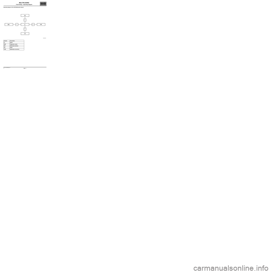
Operating diagram of the CAN Multimedia network
Number Description
E1 Splice
OBD Diagnostic socket
653 Multimedia interface
261 Radio
1959 Multimedia connection
OBD653
0
1
23
E1
2611959
Page 18 of 33
88B-18V3 MR-413-X44-88B000$060.mif
MULTIPLEXING
Fault finding – Configuration88B
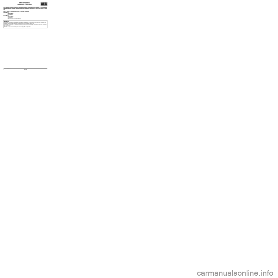
First repair the computer containing the multiplex network configuration (A2/A3 display) in order to display
the screen with the multiplex network configuration diagram for the vehicle on which fault finding is being
run.
Here is the list of computers according to the radio equipment:
Radio R1-08:
–Radio R1-08
–A2 display
Radio R2-08:
–Radio R2-08
–A3 display
–Multimedia connection (C-box)
IMPORTANT
A computer connected to the multiplex network but not declared as being among the computers containing the
multiplex network configuration will not be checked in the multiplex network test.
Correct the configuration by declaring the missing computer as present in the computer or computers containing
the configuration.
Start the multiplex network test again after modifying the configuration.
Page 19 of 33
88B-19V3 MR-413-X44-88B000$060.mif
MULTIPLEXING
Fault finding – Configuration88B
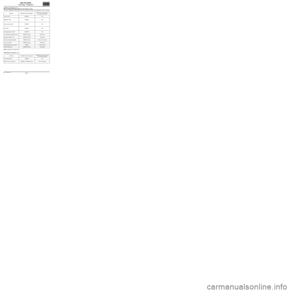
CAN Vehicle configuration screen
Make sure that the information displayed on the two tabs is correct.
The same configuration information for the two computers is essential for displaying the network topology.
Option: depending on equipment level
CAN Multimedia configuration screen Computer Multiplex network configurationConfiguration of computers that
can support fault finding
Injection (120) PRESENT YES
ABS/ESP (1094) PRESENT YES
Instrument panel (247) PRESENT YES
UCH (645) PRESENT YES
Airbag/pretensioners (756) PRESENT YES
Air conditioning (regulated) (419) PRESENT (option) YES (option)
Sequential gearbox (119) PRESENT (option) YES (option)
Power-assisted steering (502) ABSENT (option) YES (on K line) (option)
Rev counter (995) PRESENT (option) YES (option)
Parking distance control (1222) ABSENT YES (on K line)
A2/A3 display (653) PRESENT (option) YES (option)
Computer Multiplex network configurationConfiguration of computers that
can support fault finding
A2/A3 display (653) PRESENT YES
Radio R1-08 or R2-08 (261) PRESENT or ABSENT (option) YES or NO (option)
Page 24 of 33
88B-24
AFTER REPAIRRun the multiplex network test again using the diagnostic tool.
Clear the stored faults on all the computers connected to the network.
Deal with any other faults.
V3 MR-413-X44-88B000$070.mif
MULTIPLEXING
Fault finding – Interpretation of faults88B
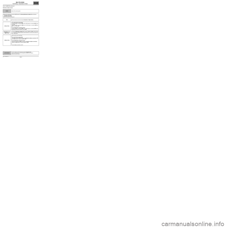
FAULTY COMPUTER (continued 1)
Multimedia multiplex network
NOTESSwitch off the vehicle ignition.
Measure the resistance of component 225 between the following Multimedia multiplex line connections:
–connection code 107X
–connection code 107W
What is the value of the resistance?
0 ΩΩ Ω ΩThe two lines are in short circuit (see Introduction - Repair advice).
60 ΩΩ Ω Ω
± 10 ΩΩ Ω Ω
For radio R1-08 and radio R2-08:
Check for earth on connection MA0, and for +12 V supply on connection BCP4 to the
radio 261.
Check for earth on connection NAM, and for +12 V supply on connection BCP4 and
BPT to the display 653.
For the Multimedia connection (C-box):
Check for earth on connection NAM, and for +12 V supply on connection BCP4 to the
Multimedia connection computer (C-box) 1959.
BETWEEN 70 ΩΩ Ω Ω
AND 110 ΩΩ Ω ΩFor each of Multimedia multiplex line connections 107X and 107W, check that there
is no interference resistance and then check that there is no short circuit to earth or to
the + battery feed.
120 ΩΩ Ω Ω
± 10 ΩΩ Ω Ω
Open circuit on one or both lines
For radio R1-08 and radio R2-08
Disconnect component 261 and check the multimedia multiplex connections 107X
and 107W between components 225 and 261.
For the Multimedia connection (C-box):
Disconnect component 1959 and check the multimedia multiplex connections
107X and 107W between components 225 and 1959.
Is the multiplex connection correct?
Page 25 of 33
88B-25
AFTER REPAIRRun the multiplex network test again using the diagnostic tool.
Clear the stored faults on all the computers connected to the network.
Deal with any other faults.
V3 MR-413-X44-88B000$070.mif
MULTIPLEXING
Fault finding – Interpretation of faults88B
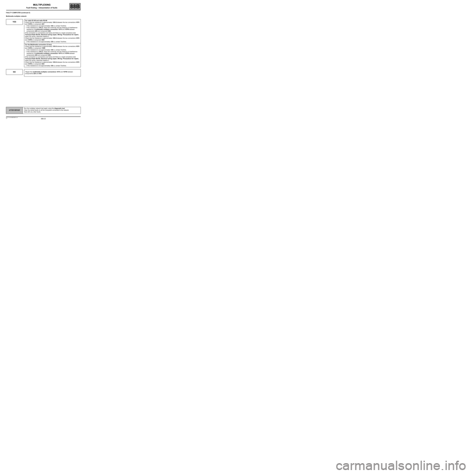
FAULTY COMPUTER (continued 2)
Multimedia multiplex network
YESFor radio R1-08 and radio R2-08
Check that the resistance is approximately 120 ΩΩ Ω Ω
between the two connections 107X
and 107W on component 261:
–If the resistance is not approximately 120 Ω, contact Techline.
–If the resistance is 120 ΩΩ Ω Ω
, check the continuity and the absence of interference
resistance of multimedia multiplex connection 107X and 107W between
components 225 and component 653.
If the connection or connections are faulty and there is a repair procedure (see
Technical Note 6015A, Electrical wiring repair, Wiring: Precautions for repair),
repair the wiring, otherwise replace it.
Check that the resistance is approximately 120 ΩΩ Ω Ω
between the two connections 107X
and 107W on component 653:
–If the resistance is not approximately 120 Ω, contact Techline.
For the Multimedia connection (C-box)
Check that the resistance is approximately 120 ΩΩ Ω Ω
between the two connections 107X
and 107W on component 1959:
–If the resistance is not approximately 120 Ω, contact Techline.
–If the resistance is 120 ΩΩ Ω Ω
, check the continuity and the absence of interference
resistance of multimedia multiplex connection 107X and 107W between
components 225 and component 653
If the connection or connections are faulty and there is a repair procedure (see
Technical Note 6015A, Electrical wiring repair, Wiring: Precautions for repair),
repair the wiring, otherwise replace it.
Check that the resistance is approximately 120 ΩΩ Ω Ω
between the two connections 107X
and 107W on component 653:
–If the resistance is not approximately 120 Ω, contact Techline.
NO Repair the multimedia multiplex connections 107X and 107W between
components 225 and 653.