turbocharging RENAULT TWINGO 2009 2.G Electrical Equipment - Petrol Injection User Guide
[x] Cancel search | Manufacturer: RENAULT, Model Year: 2009, Model line: TWINGO, Model: RENAULT TWINGO 2009 2.GPages: 348
Page 67 of 348
17B-67V7 MR-413-X44-17B000$131.mif
PETROL INJECTION
Fault finding – Interpretation of faults17B
SIM 32 Injection
Program no.: D3
Vdiag No.: 44, 4C, 50
and 54
Vdiag 54 only
DF054
PRESENT
OR
STOREDTURBOCHARGING SOLENOID VALVE CONTROL CIRCUITCO: Open circuit
CC.0: Short circuit to earth
CC.1: Short circuit to + 12 V
1.DEF: EOBD
NOTESConditions for applying the fault finding procedure to stored faults:
The fault is declared present after the ignition is switched on or after the engine has
been running at an engine speed above 600 rpm.
Special notes:
–OBD warning light illuminated.
–Throttle valve defect mode type 6.
Use the Wiring Diagrams Technical Note for NEW TWINGO, E33, CLIO III, or
MODUS.
Check the cleanliness, condition, and fitting of the turbocharging solenoid valve (component code 436).
If the connector is faulty and there is a repair method (see Technical Note 6015A, Repairing electrical wiring,
Wiring: Precautions for repair), repair the connector, otherwise replace the wiring.
If the fault is still present, manipulate the wiring harness in order to note a change in fault status (present
→
stored).
Check the condition of the engine management computer connector (component code 120).
Look for possible damage to the wiring harness.
If the connector is faulty and there is a repair method (see Technical Note 6015A, Repairing electrical wiring,
Wiring: Precautions for repair), repair the connector, otherwise replace the wiring.
Check for +12 V on connection 3AHN of the turbocharger solenoid valve, component code 436.
If +12 V is not present, check the insulation, continuity, and the absence of interference resistance on
connection:
●3AHN between components 120 and 436.
If the connection is faulty and if there is a repair procedure (see Technical Note 6015A, Electrical wiring repair,
Wiring: Precautions for repair), repair the wiring, otherwise replace it.
SIM32_V54_DF054
AFTER REPAIRDeal with any other faults. Clear the fault memory.
Switch off the ignition, wait 1 minute and carry out a road test followed by a check with
the diagnostic tool.
Page 68 of 348
17B-68V7 MR-413-X44-17B000$131.mif
PETROL INJECTION
Fault finding – Interpretation of faults17B
SIM 32 Injection
Program no.: D3
Vdiag No.: 44, 4C, 50
and 54
DF054
CONTINUED
If the fault is still present, disconnect the battery and the injection computer.
Check the insulation, continuity, and the absence of interference resistance on connection:
●3AT between components 120 and 436.
If the connection is faulty and if there is a repair procedure (see Technical Note 6015A, Electrical wiring repair,
Wiring: Precautions for repair), repair the wiring, otherwise replace it.
If the fault is still present, measure the resistance of the turbocharging solenoid valve between connections 3AHN
and 3AT.
If the resistance of the turbocharger solenoid valve is not between:
●21.8 Ω < X < 24.2 Ω at 23˚C, replace the solenoid valve.
If the fault is still present, contact the Techline.
AFTER REPAIRDeal with any other faults. Clear the fault memory.
Switch off the ignition, wait 1 minute and carry out a road test followed by a check with
the diagnostic tool.
Page 154 of 348
17B-154V7 MR-413-X44-17B000$133.mif
PETROL INJECTION
Fault finding – Interpretation of faults17B
SIM 32 Injection
Program no.: D3
Vdiag No.: 44, 4C, 50
and 54
Only Vdiag 54
DF569
PRESENT
OR
STOREDTURBOCHARGING CIRCUIT
1.DEF: Signal outside lower limit
2.DEF: Signal outside upper limit
3.DEF: OBD
NOTESConditions for applying the fault finding procedure to stored faults
The fault is declared present with the engine running.
Special note:
Defect mode 4: speed limited to less than 66 mph (110 km/h) in 5th and 6
th and the
accelerator pedal feels spongy.
Defect mode 5: the ESP and Cruise control - Speed limiter are deactivated.
Defect mode 6: the wastegate is not controlled and opens freely.
The engine runs without turbocharging, like a naturally aspirated engine.
Use the Wiring Diagrams Technical Note for NEW TWINGO, E33, CLIO III, or
MODUS.
Check the connection of the turbocharging ducts.
Check the condition of the connector of the turbocharger pressure sensor (component code 1071), of the
wastegate solenoid valve (component code 436), and of the engine management computer (component
code 120).
If the connectors are faulty and if there is a repair procedure (see Technical Note 6015A, Repairing electrical
wiring, Wiring: Precautions for repair), repair the connector, otherwise replace the wiring.
Use the universal bornier to check the insulation and continuity of the following connections:
●3AHN between components 436 and 120,
●3AT between components 436 and 120,
●3LN between components 1071 and 120,
●3LP between components 1071 and 120,
●3LQ between components 1071 and 120.
If the connection or connections are faulty and there is a repair procedure (see Technical Note 6015A, Electrical
wiring repair, Wiring: Precautions for repair), repair the wiring, otherwise replace it.
If the fault is still present, contact the Techline.
SIM32_V54_DF569
AFTER REPAIRFollow the instructions to confirm repair:
–If the fault is present, continue to deal with the fault.
–If the fault is stored, ignore it.
Deal with any other faults.
Clear the stored faults.
Page 245 of 348
17B-245V7 MR-413-X44-17B000$152.mif
PETROL INJECTION
Fault finding – Interpretation of statuses17B
SIM 32 Injection
Program no.: D3
Vdiag No.: 44, 4C, 50
and 54
ET567DEFECT MODE TYPE 4
STATUS
DEFINITIONACTIVE: This status indicates that defect mode type 4 is active.
INACTIVE: This status indicates that defect mode type 4 is inactive.
NOTESThere must be no present or stored faults.
This type groups together faults affecting the motorised throttle valve monitoring system, the pedal and the
turbocharging circuit for which there is a backup operating mode that is viable for the system.
The associated defect mode is a limitation of the throttle opening according to the engine speed. This is expressed
by limiting the speed to less than 66 mph (110 km/h) in 5
th and 6th and the accelerator pedal feels "soft".
SIM32_V44_ET567/SIM32_V4C_ET567/SIM32_V50_ET567/SIM32_V54_ET567
AFTER REPAIRCarry out a road test followed by a check with the diagnostic tool.
Page 246 of 348
17B-246V7 MR-413-X44-17B000$152.mif
PETROL INJECTION
Fault finding – Interpretation of statuses17B
SIM 32 Injection
Program no.: D3
Vdiag No.: 44, 4C, 50
and 54
ET568TYPE 5 DEFECT MODE
STATUS
DEFINITIONACTIVE: This status indicates that defect mode type 5 is active.
INACTIVE: This status indicates that defect mode type 5 is inactive.
NOTESThere must be no present or stored faults.
This type groups together faults affecting the pressure, the throttle valve control by the torque structure and the
turbocharging pressure.
Its effect is to go into pedal feedback mode instead of the permanent torque structure. The ESP and cruise control/
speed limiter systems are deactivated. The automatic or sequential gearbox goes into safe mode. The engine
management no longer accepts requests from the gearbox, and sends torque values by default to the multiplex
network.
SIM32_V44_ET568/SIM32_V4C_ET568/SIM32_V50_ET568/SIM32_V54_ET568
AFTER REPAIRCarry out a road test followed by a check with the diagnostic tool.
Page 247 of 348
17B-247V7 MR-413-X44-17B000$152.mif
PETROL INJECTION
Fault finding – Interpretation of statuses17B
SIM 32 Injection
Program no.: D3
Vdiag No.: 44, 4C, 50
and 54
ET569DEFECT MODE TYPE
6
STATUS
DEFINITIONACTIVE: This status indicates that defect mode type 6 is active.
INACTIVE: This status indicates that defect mode type 6 is inactive.
NOTESThere must be no present or stored faults.
This type groups the faults affecting the wastegate control in turbocharged vehicles.
Defect mode enables the engine to operate as a naturally aspirated engine.
The wastegate is no longer controlled and opens freely. The vehicle operates without turbocharging: loss of
turbocharger effectiveness (brisk engine performance, acceleration, recovery, etc.); operation as a naturally
aspirated engine.
Entry into type 1 to 5 defect mode always leads to the application of type 6 in turbocharged versions.
SIM32_V44_ET569/SIM32_V4C_ET569/SIM32_V50_ET569/SIM32_V54_ET569
AFTER REPAIRCarry out a road test followed by a check with the diagnostic tool.
Page 263 of 348
17B-263V7 MR-413-X44-17B000$160.mif
17B
SIM 32 Injection
Program no.: D3
Vdiag No.: 44, 4C, 50
and 54
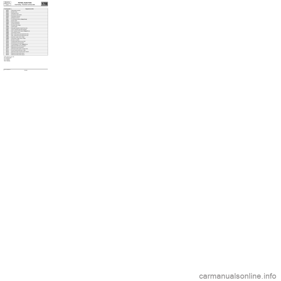
* OCR: Opening cyclic ratio
* EV: Solenoid valve
* mot: motorised
* app.: applying
* AAC: Camshaft
Tool ParameterDiagnostic tool title
PR014Idling speed correction
PR015Engine torque
PR018Estimated air flow
PR030Accelerator pedal position
PR035Atmospheric pressure
PR037Refrigerant pressure
PR041Turbocharger pressure (Vdiag 54 only)
PR055Engine speed
PR059Inlet air temperature
PR064Coolant temperature
PR071Computer feed voltage
PR089Vehicle speed
PR090Idle speed regulation programming value
PR091OCR* Theoretical idle speed regulation
PR094AAC* dephaser OCR* setpoint (Vdiag 4C only)
PR095Anti-pinking correction
PR096Mot.* throttle upper stop programmed value.
PR097Mot.* throttle lower stop programmed value.
PR098Upstream oxygen sensor voltage
PR099Downstream oxygen sensor voltage
PR101Duration of injection
PR102Canister bleed solenoid valve OCR*
PR103Instantaneous fuel consumption
PR104Turbocharging EV* OCR* (Vdiag 54 only)
PR105Mileometer OBD fault warning light lit
PR106Mileometer fault warning light lit
PR111Motorised throttle position corrected value.
PR113Lower throttle stop after app.* offset
PR116Motorised throttle corrected position setpoint
PR118Measured throttle position gang 1
PR119Measured throttle position gang 2
PETROL INJECTION
Fault finding – Parameter summary table
Page 270 of 348
17B-270V7 MR-413-X44-17B000$171.mif
PETROL INJECTION
Fault finding – Interpretation of parameters17B
SIM 32 Injection
Program no.: D3
Vdiag No.: 44, 4C, 50
and 54
PR035ATMOSPHERIC PRESSURE
PARAMETER
DEFINITIONThis parameter indicates the atmospheric pressure in bar. The sensor is integrated in
the computer.
NOTESSpecial notes:
Only perform these tests if the parameters do not correspond with the system operation
programming.
Use the Wiring Diagrams Technical Note for NEW TWINGO, E33, CLIO III
or MODUS.
Conformity check with engine stopped and ignition on, or engine running, and engine coolant
temperature > 80˚C
The atmospheric pressure value is:
PR035 ≈ 1 bar +/- 0.20 bar
In the event of a fault, consult the interpretation of DF004 Turbocharging pressure sensor circuit.
Check the cleanliness and condition of the atmospheric pressure sensor and its connections (component
code 147) and the engine management computer (component code 120).
If the connector or connectors are faulty and if there is a repair procedure (see Technical Note 6015A, Repairing
electrical wiring, Wiring: Precautions for repair), repair the connector, otherwise replace the wiring.
On the atmospheric pressure sensor, component code 147, check the resistance between connections 3LG
and 3CK.
If the resistance is not X 50 kΩ, replace the sensor.
SIM32_V44_PR035/SIM32_V4C_PR035/SIM32_V50_PR035/SIM32_V54_PR035
AFTER REPAIRCarry out a road test followed by a check with the diagnostic tool.
Page 273 of 348
17B-273V7 MR-413-X44-17B000$171.mif
PETROL INJECTION
Fault finding – Interpretation of parameters17B
SIM 32 Injection
Program no.: D3
Vdiag No.: 44, 4C, 50
and 54
Vdiag 54 only
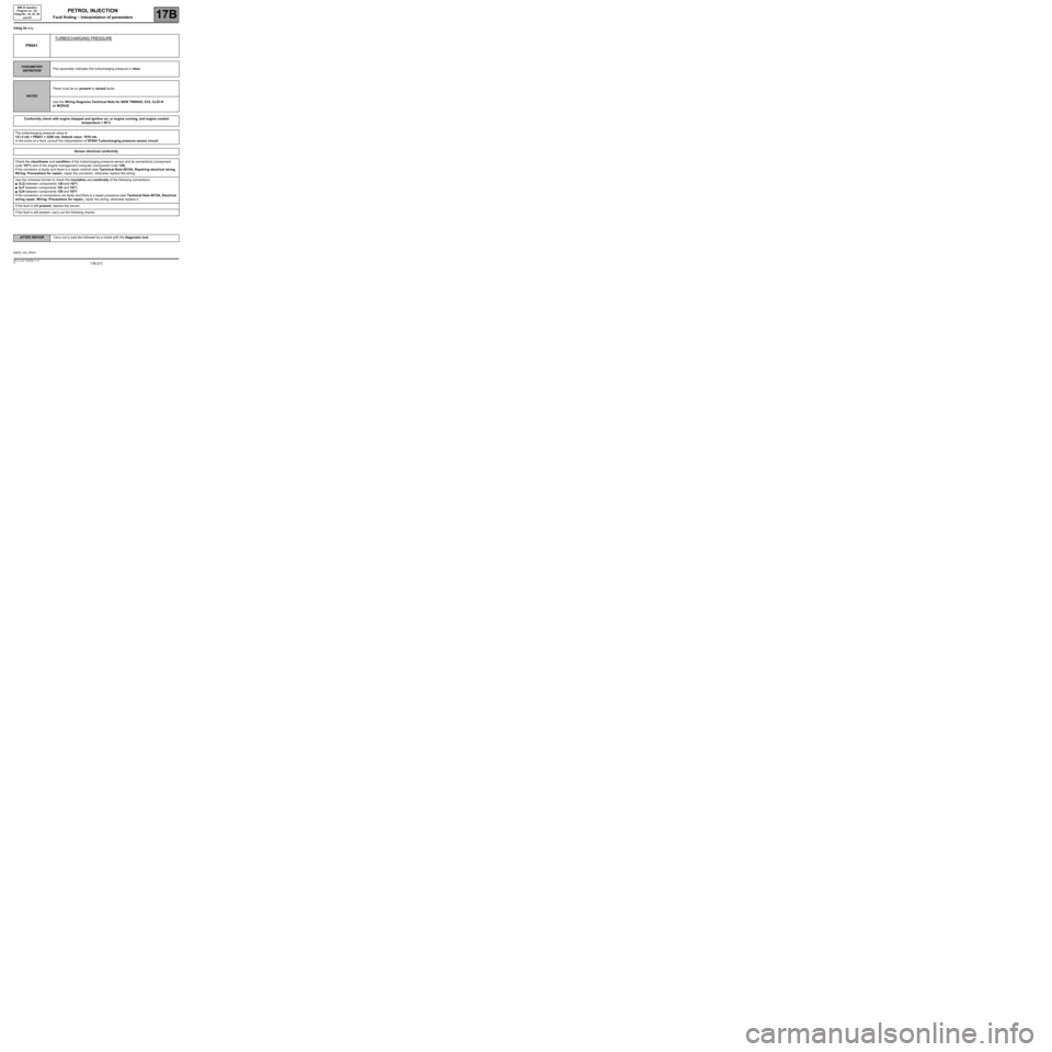
PR041TURBOCHARGING PRESSURE
PARAMETER
DEFINITIONThis parameter indicates the turbocharging pressure in mbar.
NOTESThere must be no present or stored faults.
Use the Wiring Diagrams Technical Note for NEW TWINGO, E33, CLIO III
or MODUS.
Conformity check with engine stopped and ignition on, or engine running, and engine coolant
temperature > 80˚C
The turbocharging pressure value is:
121.5 mb < PR041 < 2200 mb, Default value: 1016 mb.
In the event of a fault, consult the interpretation of DF004 Turbocharging pressure sensor circuit.
Sensor electrical conformity
Check the cleanliness and condition of the turbocharging pressure sensor and its connections (component
code 1071) and of the engine management computer (component code 120).
If the connector is faulty and there is a repair method (see Technical Note 6015A, Repairing electrical wiring,
Wiring: Precautions for repair), repair the connector, otherwise replace the wiring.
Use the universal bornier to check the insulation and continuity of the following connections:
●3LQ between components 120 and 1071,
●3LP between components 120 and 1071,
●3LN between components 120 and 1071.
If the connection or connections are faulty and there is a repair procedure (see Technical Note 6015A, Electrical
wiring repair, Wiring: Precautions for repair), repair the wiring, otherwise replace it.
If the fault is still present, replace the sensor.
If the fault is still present, carry out the following checks:
SIM32_V54_PR041
AFTER REPAIRCarry out a road test followed by a check with the diagnostic tool.
Page 274 of 348
17B-274V7 MR-413-X44-17B000$171.mif
PETROL INJECTION
Fault finding – Interpretation of parameters17B
SIM 32 Injection
Program no.: D3
Vdiag No.: 44, 4C, 50
and 54
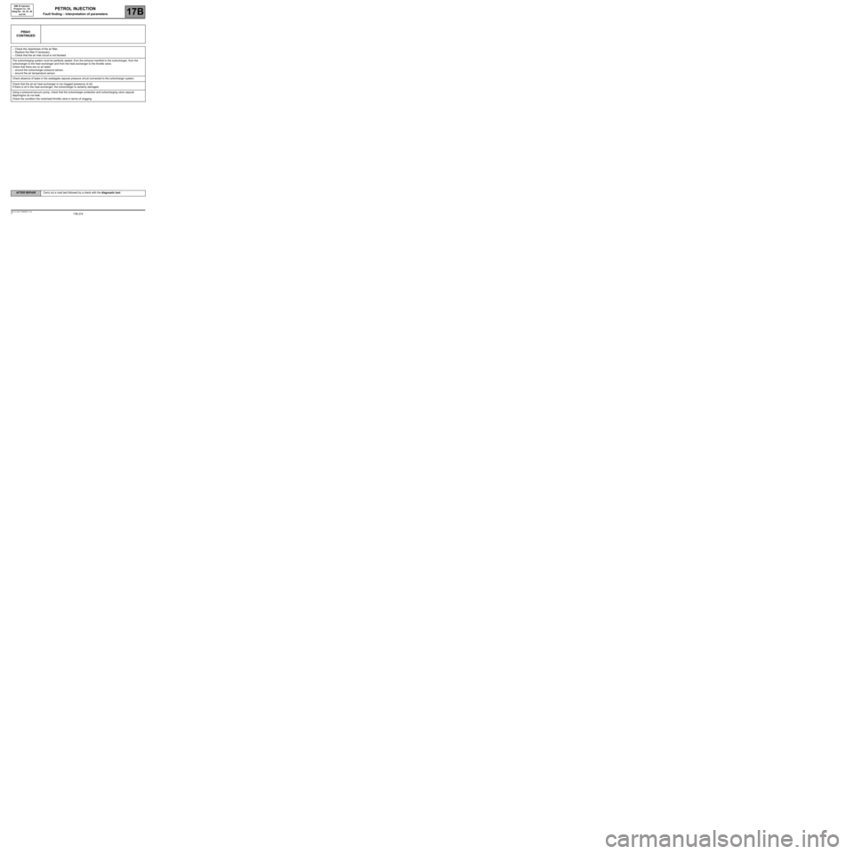
PR041
CONTINUED
–Check the cleanliness of the air filter.
–Replace the filter if necessary.
–Check that the air inlet circuit is not blocked.
The turbocharging system must be perfectly sealed, from the exhaust manifold to the turbocharger, from the
turbocharger to the heat exchanger and from the heat exchanger to the throttle valve.
Check that there are no air leaks:
–around the turbocharger pressure sensor,
–around the air temperature sensor.
Check absence of leaks in the wastegate capsule pressure circuit connected to the turbocharger system.
Check that the air-air heat exchanger is not clogged (presence of oil).
If there is oil in the heat exchanger, the turbocharger is certainly damaged.
Using a pressure/vacuum pump, check that the turbocharger protection and turbocharging valve capsule
diaphragms do not leak.
Check the condition the motorised throttle valve in terms of clogging.
AFTER REPAIRCarry out a road test followed by a check with the diagnostic tool.