display RENAULT TWINGO 2009 2.G Engine Diesel Injection Workshop Manual
[x] Cancel search | Manufacturer: RENAULT, Model Year: 2009, Model line: TWINGO, Model: RENAULT TWINGO 2009 2.GPages: 269
Page 196 of 269
13B-196
AFTER REPAIRDeal with any faults displayed by the diagnostic tool.
Clear the computer fault memory.
Carry out a road test followed by another check with the diagnostic tool.
V6 MR-413-X44-13B000$170.mif
DIESEL INJECTION
Fault finding – Interpretation of parameters13B
DCM 1.2 Injection
Program No.: 4D
Vdiag No.: 4C, 50, 54,
58, 5C
PR568PEDAL POSITION (GANG 1)
PARAMETER
DEFINITIONThis parameter indicates the accelerator pedal position gang 1 as a %.
Conformity check: Engine stopped, ignition on or engine running.
PR568 ≈ 16%.
In the event of a fault, apply the interpretation of DF008 Pedal sensor circuit gang 1.
DCM1.2_V4C_PR568/DCM1.2_V50_PR568/DCM1.2_V54_PR568/DCM1.2_V58_PR568/DCM1.2_V5C_PR568
Page 197 of 269
13B-197
AFTER REPAIRDeal with any faults displayed by the diagnostic tool.
Clear the computer fault memory.
Carry out a road test followed by another check with the diagnostic tool.
V6 MR-413-X44-13B000$170.mif
DIESEL INJECTION
Fault finding – Interpretation of parameters13B
DCM 1.2 Injection
Program No.: 4D
Vdiag No.: 4C, 50, 54,
58, 5C
PR569PEDAL POSITION GANG
2
PARAMETER
DEFINITIONThis parameter indicates the accelerator pedal position gang 2 as a %.
Conformity check: Engine stopped, ignition on or engine running.
PR569 ≈ 7%.
In the event of a fault, apply the interpretation of DF009 Pedal sensor circuit gang 2.
DCM1.2_V4C_PR569/DCM1.2_V50_PR569/DCM1.2_V54_PR569/DCM1.2_V58_PR569/DCM1.2_V5C_PR569
Page 198 of 269
13B-198
AFTER REPAIRDeal with any faults displayed by the diagnostic tool. Clear the computer fault
memory.
Carry out a road test followed by another check with the diagnostic tool.
V6 MR-413-X44-13B000$170.mif
DIESEL INJECTION
Fault finding – Interpretation of parameters13B
DCM 1.2 Injection
Program No.: 4D
Vdiag No.: 48, 4C, 50,
54, 58, 5C
PR730AIR FLOW SENSOR TEMPERATURE
PARAMETER
DEFINITIONThis parameter indicates the air temperature of the flowmeter in °C.
NOTESSpecial notes:
Depending on the engine type, the air temperature is given by the air flowmeter or the
exterior air temperature sensor.
Conformity check: Engine stopped and ignition on, or engine running and engine coolant
temperature > 80
°C
Check the condition of the air flow sensor connections.
If the connector is faulty and there is a repair method (see Technical Note 6015A, Repairing electrical wiring,
Wiring: Precautions for repair), repair the connector, otherwise replace the wiring.
If necessary, replace the sensor (see MR 364 (Mégane II), MR 370 (Scénic II), MR 385 (Modus), MR 392 (Clio III),
MR 411 (New Twingo), MR 417 (Kangoo 2), Mechanical, 12A, Fuel mixture, Air flowmeter: Removal -
Refitting).
Measure the resistance between the following connections:
(vehicle with flowmeter)
–3B and 3DW of component 799;
(vehicle without flowmeter)
–3PB and 3KQ of component 272,
–3SH and 3KQ of component 272,
–3JQ and 3KQ of component 272.
If the connection or connections are faulty and there is a repair procedure (see Technical Note 6015A, Electrical
wiring repair, Wiring: Precautions for repair), repair the wiring, otherwise replace the wiring.
DCM1.2_V48_PR730/DCM1.2_V4C_PR730/DCM1.2_V50_PR730/DCM1.2_V54_PR730/DCM1.2_V58_PR730/DCM1.2_V5C_PR730
Page 199 of 269
13B-199
AFTER REPAIRDeal with any faults displayed by the diagnostic tool. Clear the computer fault
memory.
Carry out a road test followed by another check with the diagnostic tool.
V6 MR-413-X44-13B000$170.mif
DIESEL INJECTION
Fault finding – Interpretation of parameters13B
DCM 1.2 Injection
Program No.: 4D
Vdiag No.: 48, 4C, 50,
54, 58, 5C
PR730
CONTINUED
If the resistance of the air flowmeter or the exterior air temperature sensor is not:
(theoretical values for flowmeter K9K 724, 766, 768, 800 and 802)
at -10
°C: 8716 Ω < X < 9688 Ω
at 0
°C: 5497 Ω < X < 6051 Ω
at 10
°C: 3553 Ω < X < 3875 Ω
at 20
°C: 2353 Ω < X < 2543 Ω
at 30
°C: 1613 Ω < X < 1729 Ω
(theoretical values for exterior air temperature sensor K9K 750, 752, 740 and 812)
at -10
°C: 8623 Ω < X < 10454 Ω
at 25
°C: 1928 Ω < X < 2174 Ω
at 50
°C: 763 Ω < X < 857 Ω,
replace the air temperature/pressure sensor or the exterior air temperature sensor, component code 272 (see
MR 364 (Mégane II), MR 370 (Scénic II), MR 385 (Modus), MR 392 (Clio III), MR 411 (New Twingo), MR 417
(Kangoo 2), Mechanical, 12A, Fuel mixture, Air flowmeter: Removal - Refitting).
Page 200 of 269
13B-200
AFTER REPAIRDeal with any faults displayed by the diagnostic tool. Clear the computer fault
memory.
Carry out a road test followed by another check with the diagnostic tool.
V6 MR-413-X44-13B000$170.mif
DIESEL INJECTION
Fault finding – Interpretation of parameters13B
DCM 1.2 Injection
Program No.: 4D
Vdiag No.: 54, 5C
PR873OIL OXIDATION SIGNAL
PARAMETER
DEFINITIONThis parameter indicates the vehicle distance in km when the warning requesting the
oil change was displayed on the instrument panel.
NOTESThis parameter is not to be interpreted:
–on the K9K812 engine,
–if PR873 = 0 (Vdiag 58 only).
Conformity check: Engine stopped, ignition on or engine running.
The oil status is calculated by the oxidation program in the injection computer, depending on the engine revs.
When this count reaches a certain threshold before the end of the oil change period, the injection computer sends
a signal to the instrument panel, which will display "service required soon". PR873 corresponds to the vehicle
distance at the time this signal is sent.
The instrument panel computer will then count 900 miles (1500 km) before displaying the message "service
required".
IMPORTANT
When the message Service required appears on the instrument panel, the customer must arrange an oil change
within the remaining 900 miles (1500 km).
DCM1.2_V54_PR873/DCM1.2_V5C_PR873
Page 202 of 269
13B-202
AFTER REPAIRDeal with any faults displayed by the diagnostic tool.
Clear the computer fault memory.
Carry out a road test followed by another check with the diagnostic tool.
V6 MR-413-X44-13B000$170.mif
DIESEL INJECTION
Fault finding – Interpretation of parameters13B
DCM 1.2 Injection
Program No.: 4D
Vdiag No.: 54
PR879MAXIMUM AUTHORISED SPEED
PARAMETER
DEFINITIONThis parameter indicates the maximum authorised speed in mph (km/h) requested by
the customer using command SC040 Speed limiter.
NOTESSpecial notes:
It is possible to modify the value of PR879 using command SC040 Speed limiter.
This parameter is valid only on Kangoo 2.
Conformity check: Engine stopped and ignition on, or engine running and engine coolant
temperature > 80
°C
If ET741 "Optional vehicle speed restriction" is ACTIVE, the value of PR879 is between 18 mph (30 km/h) and
150 mph (250 km/h).
In the event of a fault or modification of this speed, use command SC040 Speed limiter.
DCM1.2_V54_PR879
Page 203 of 269
13B-203
AFTER REPAIRDeal with any faults displayed by the diagnostic tool. Clear the computer fault
memory.
Carry out a road test followed by another check with the diagnostic tool.
V6 MR-413-X44-13B000$170.mif
DIESEL INJECTION
Fault finding – Interpretation of parameters13B
DCM 1.2 Injection
Program No.: 4D
Vdiag No.: 54, 5C
PR932DEGREE OF ENGINE OIL DILUTION
PARAMETER
DEFINITIONThis parameter gives the value for the degree of oil wear in %.
NOTESThis parameter is not to be interpreted:
–on the K9K812 engine,
–if PR932 = 0 (Vdiag 58 only).
Conformity check: Engine stopped, ignition on or engine running.
PR932 = 0% for the first 900 miles (1500 km), beyond this value the PR932 changes regularly until it
reaches 100%.
If PR932 = 100% it means that the oil should be changed.
DCM1.2_V54_PR932/DCM1.2_V5C_PR932
Page 204 of 269
13B-204
AFTER REPAIRDeal with any faults displayed by the diagnostic tool. Clear the computer fault
memory.
Carry out a road test followed by another check with the diagnostic tool.
V6 MR-413-X44-13B000$170.mif
DIESEL INJECTION
Fault finding – Interpretation of parameters13B
DCM 1.2 Injection
Program No.: 4D
Vdiag No.: 54, 5C
PR1015OIL SERVICE INTERVAL
PARAMETER
DEFINITIONThis parameter indicates the vehicle distance before the next oil change in miles (km).
NOTES–This parameter is not to be interpreted:
–on the K9K812 engine,
–if PR1015 = 50000 (Vdiag 58 only).
Conformity check: Engine stopped, ignition on or engine running.
20000 km < PR1015 < 0 km.
This parameter decreases to 0 according to the vehicle distance and the degree of oil wear.
DCM1.2_V54_PR1015/DCM1.2_V5C_PR1015
Page 219 of 269
13B-219V6 MR-413-X44-13B000$190.mif
DIESEL INJECTION
Fault finding – Tests13B
DCM 1.2 Injection
Program No.: 4D
Vdiag No.: 48, 4C, 50,
54, 58, 5C
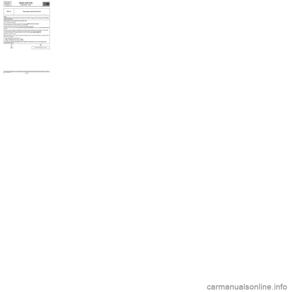
TEST 10 Turbocharger solenoid valve check
Note:
No turbocharger control solenoid valve present on the K9K 740 engine for New Twingo and the K9K 800
engine for Kangoo 2.
Checking the vacuum at the pressure regulator inlet
Run the engine at idle speed.
Check the engine temperature using the CLIP parameter PR064 Coolant temperature.
Let the engine warm up until the temperature reaches 80
°C.
Disconnect the vacuum pipe from the end piece of the pressure regulator.
Connect a vacuum pressure gauge to the end of the disconnected pipe and put it in the vacuum measurement
position.
Perform a quick acceleration by depressing the accelerator pedal completely and then releasing it immediately.
The total duration of pressing and holding in the full load position must not exceed 1 second.
During this acceleration, the engine speed must reach a value between 3000 and 4000 rpm.
Repeat the operation 3 times.
Read the maximum vacuum posted by the pressure gauge during the increase and decrease in the speed and after
the return to idle speed.
Tolerance intervals for the vacuum are:
–1 bar < CORRECT vacuum value < - 0.6 bar
–0.6 bar < INCORRECT vacuum value < 0 bar
Is the vacuum at the turbocharging pressure regulator inlet displayed on the vacuum gauge within
the tolerance interval?
The solenoid valve is in order.
NOYES
A
DCM1.2_V48_TEST10/DCM1.2_V4C_TEST10/DCM1.2_V50_TEST10/DCM1.2_V54_TEST10/DCM1.2_V58_TEST10/DCM1.2_V5C_TEST10
Page 220 of 269
13B-220V6 MR-413-X44-13B000$190.mif
DIESEL INJECTION
Fault finding – Tests13B
DCM 1.2 Injection
Program No.: 4D
Vdiag No.: 48, 4C, 50,
54, 58, 5C
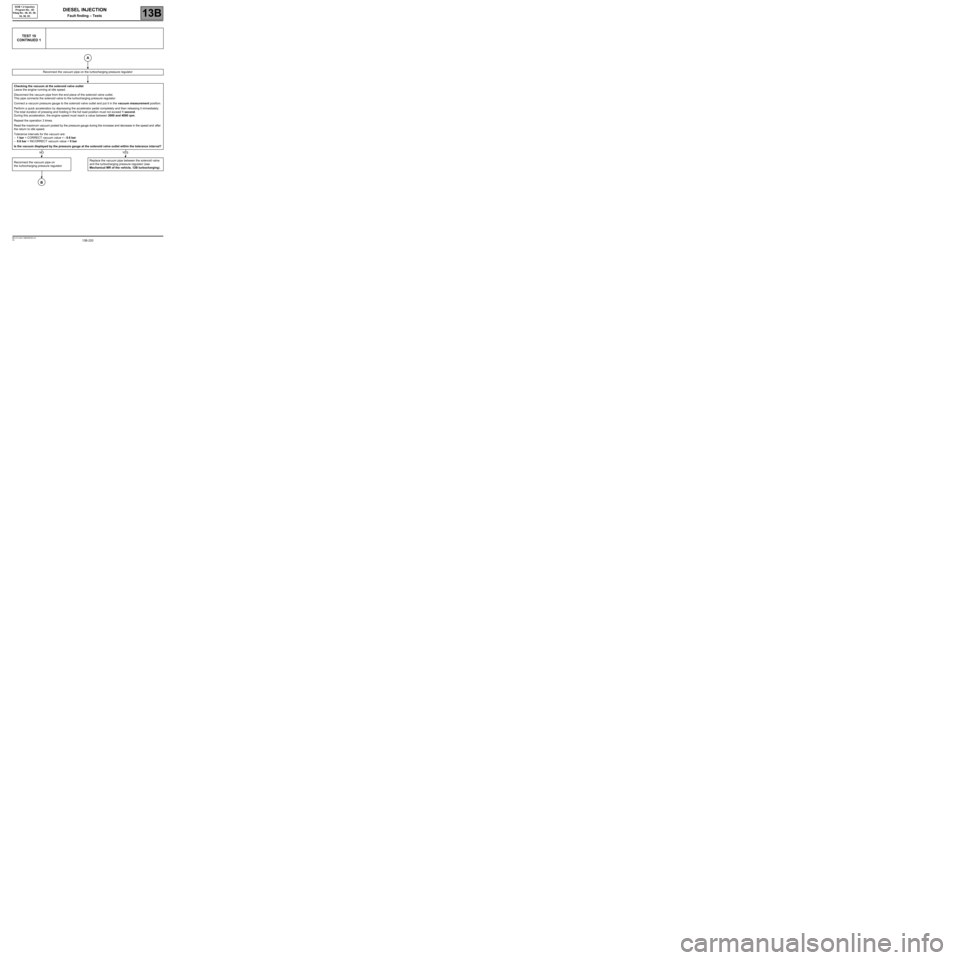
TEST 10
CONTINUED 1
Reconnect the vacuum pipe on the turbocharging pressure regulator
Checking the vacuum at the solenoid valve outlet
Leave the engine running at idle speed.
Disconnect the vacuum pipe from the end piece of the solenoid valve outlet.
This pipe connects the solenoid valve to the turbocharging pressure regulator.
Connect a vacuum pressure gauge to the solenoid valve outlet and put it in the vacuum measurement position.
Perform a quick acceleration by depressing the accelerator pedal completely and then releasing it immediately.
The total duration of pressing and holding in the full load position must not exceed 1 second.
During this acceleration, the engine speed must reach a value between 3000 and 4000 rpm.
Repeat the operation 3 times.
Read the maximum vacuum posted by the pressure gauge during the increase and decrease in the speed and after
the return to idle speed.
Tolerance intervals for the vacuum are:
–1 bar < CORRECT vacuum value < - 0.6 bar
–0.6 bar < INCORRECT vacuum value < 0 bar
Is the vacuum displayed by the pressure gauge at the solenoid valve outlet within the tolerance interval?
Reconnect the vacuum pipe on
the turbocharging pressure regulator Replace the vacuum pipe between the solenoid valve
and the turbocharging pressure regulator (see
Mechanical MR of the vehicle, 12B turbocharging).
A
NOYES
B