service RENAULT TWINGO 2009 2.G Engine Diesel Injection Workshop Manual
[x] Cancel search | Manufacturer: RENAULT, Model Year: 2009, Model line: TWINGO, Model: RENAULT TWINGO 2009 2.GPages: 269
Page 1 of 269
1Engine and peripherals
V6 MR-413-X44-13B000$TOC.mif
V6
13B
"The repair procedures given by the manufacturer in this document are based on the
technical specifications current when it was prepared.
The procedures may be modified as a result of changes introduced by the
manufacturer in the production of the various component units and accessories from
which his vehicles are constructed."
V6
All rights reserved by Renault s.a.s.
Edition Anglaise
Copying or translating, in part or in full, of this document or use of the service part
reference numbering system is forbidden without the prior written authority of
Renault s.a.s.
© Renault s.a.s. 2009
DIESEL INJECTION
DCM 1.2 Injection
Program No.: 4D
Vdiag No.: 48, 4C, 50, 54, 58, 5C
Fault finding – Introduction 13B - 2
Fault finding – Cleanliness guidelines 13B - 8
Fault finding – List and location of components 13B - 10
Fault finding – Function 13B - 12
Fault finding – Role of components 13B - 21
Fault finding – Replacement of components 13B - 23
Fault finding – Configuration and programming 13B - 26
Fault finding – Fault summary table 13B - 27
Fault finding – Interpretation of faults 13B - 29
Fault finding – Conformity check 13B - 125
Fault finding – Status summary table 13B - 126
Fault finding – Interpretation of statuses 13B - 127
Fault finding – Parameter summary table 13B - 169
Fault finding – Interpretation of parameters 13B - 171
Fault finding – Command summary table 13B - 205
Fault finding – Tests 13B - 207
Fault finding – Customer complaints 13B - 235
Fault finding – Fault finding charts 13B - 236
Page 15 of 269
13B-15V6 MR-413-X44-13B000$040.mif
DIESEL INJECTION
Fault finding – Function13B
DCM 1.2 Injection
Program No.: 4D
Vdiag No.: 48, 4C, 50,
54, 58, 5C
Angular position measurement
Engine speed sensor:
The angular position is measured using a magneto-inductive sensor triggered by machined teeth on the shaft
flywheel. This flywheel has sixty teeth, six degrees apart, minus two missing teeth that form a notch.
Cylinder reference sensor:
A second sensor (Hall effect) triggered by a machined tooth on the high pressure pump drive pulley (synchronised
with the camshaft), turning at half the engine speed, supplies a signal about the progress of the injection cycle.
By comparing the signals from these two sensors, the computer's APS module (Angular Position Subsystem) can
supply the entire system with the synchronisation factors, which are: the angular position of the flywheel, the engine
speed, the number of the active injector and the injection cycle timing.
This module also supplies the system with the engine speed signal.
New pump chamber filling procedure (pump boosting)
The pump lubrication goes through a booster cycle during which the pump is filled and pressurised before
"transferring" the diesel fuel to the rail.
This lubrication goes through a procedure called new pump chamber filling, which prevents starting for
approximately 10 seconds, which is the time required for filling the pump and starting. For vehicles with keys,
if the key is released before the end of this "initial starting" phase there is no need for a power latch phase to be
completed before a fresh attempt to start the vehicle.
This procedure is run after the first start in the factory, after a computer is replaced if the parameters relating to
the rail pressure have not been copied into the new computer, and also after reprogramming of the injection
computer.
Variable Low Capacity (VLC) output function
Because of the combination of several parameters such as the diesel fuel temperature, part wear, clogging of
the diesel filter etc., the system limit may be reached during its service life. If this happens, the rail pressure cannot
be maintained because the pump lacks the necessary capacity. If the pump lacks the necessary capacity, this
programming will therefore reduce the requested flow to a value that will enable the pressure monitoring system to
control the pressure again.
The customer may have noticed a loss of vehicle performance when this program is activated (depending on
the vehicle, this programming can be confirmed by ET563 Flow capacity function). This is normal operation of
the injection system.
Function: Air flow management
EGR valve control
K9K 766 and 768 (Euro 4) engines (fitted on Clio III and Modus) and K9K 724 (Euro 4) engines (fitted on
Mégane II and Scénic II) and K9K 740 engines (fitted on New Twingo) and K9K 800, 802 and 812 engines
(fitted on Kangoo 2):
The EGR (Exhaust Gas Recirculation) system consists of a DC proportional EGR valve, which incorporates
a valve position feedback potentiometer. The EGR valve is closed-loop controlled based on its position via
the potentiometer and/or based on changes in the estimated air flow.
K9K 750 and 752 (Euro 3) engines (fitted on Clio III and Modus):
The EGR system (Exhaust Gas Recirculation) consists of an EGR solenoid valve, which incorporates a valve
position feedback potentiometer. The EGR valve is closed-loop controlled based on its position via
the potentiometer and/or based on changes in the estimated air flow.
Page 19 of 269
13B-19V6 MR-413-X44-13B000$040.mif
DIESEL INJECTION
Fault finding – Function13B
DCM 1.2 Injection
Program No.: 4D
Vdiag No.: 48, 4C, 50,
54, 58, 5C
Instrument panel display
The computer manages the data display on the instrument panel relating to engine operation. This covers five
functions: the OBD warning light for European On Board Diagnostics (EOBD), pre-postheating, coolant temperature,
and Level 1 (non critical fault) and Level 2 (emergency stop) engine faults. These five functions are represented by
five warning lights or messages displayed by the trip computer.
Pre-postheating warning light
This warning light indicates that preheating is active.
Engine coolant temperature warning light
This warning light is used as an engine overheating indicator.
–In the event of overheating, it is up to the driver whether to stop the vehicle or continue driving.
OBD warning light
The OBD fault warning light is used to warn the driver of the presence of injection faults producing excessive
pollution or that the EOBD system is deactivated.
The injection computer requests illumination of the OBD warning light for a present fault only after three consecutive
driving cycles.
The visual check of the warning light when the power is switched on (automatic test procedure managed by
the instrument panel) is carried out by the injection computer. It lasts 3 seconds or until the engine starts for
the New Twingo and Kangoo 2.
If a confirmed OBD fault causes the OBD warning light to come on, there should be no flashing after the warning
light illumination test. The instrument panel will also display the message: Check emission control.
The gearbox computer, if fitted, may also request the illumination of this warning light.
Level 1 warning
If there is a minor fault, the computer may request a level 1 warning to be displayed. Usually, the instrument panel
switches on the SERVICE warning light and sends out a "Check the injection" message. Refer to the operation of the
instrument panel (see 83A, instrument panel). Note:
This warning light comes on only if the vehicle is EOBD approved.
Note:
The SERVICE warning light will come on if the instrument panel is configured as cruise control - speed
limiter present, but the function has not yet been detected by the injection computer.
Page 170 of 269
13B-170V6 MR-413-X44-13B000$160.mif
DIESEL INJECTION
Fault finding – Parameter summary table13B
DCM 1.2 Injection
Program No.: 4D
Vdiag No.: 48, 4C, 50,
54, 58, 5C
PR730Air flow sensor temperature
PR873Oil oxidation signal
PR878Increased idle speed
PR879Maximum authorised speed
PR932Rate of engine oil dilution
PR1015Oil service interval
Tool parameterDiagnostic tool title
Page 200 of 269
13B-200
AFTER REPAIRDeal with any faults displayed by the diagnostic tool. Clear the computer fault
memory.
Carry out a road test followed by another check with the diagnostic tool.
V6 MR-413-X44-13B000$170.mif
DIESEL INJECTION
Fault finding – Interpretation of parameters13B
DCM 1.2 Injection
Program No.: 4D
Vdiag No.: 54, 5C
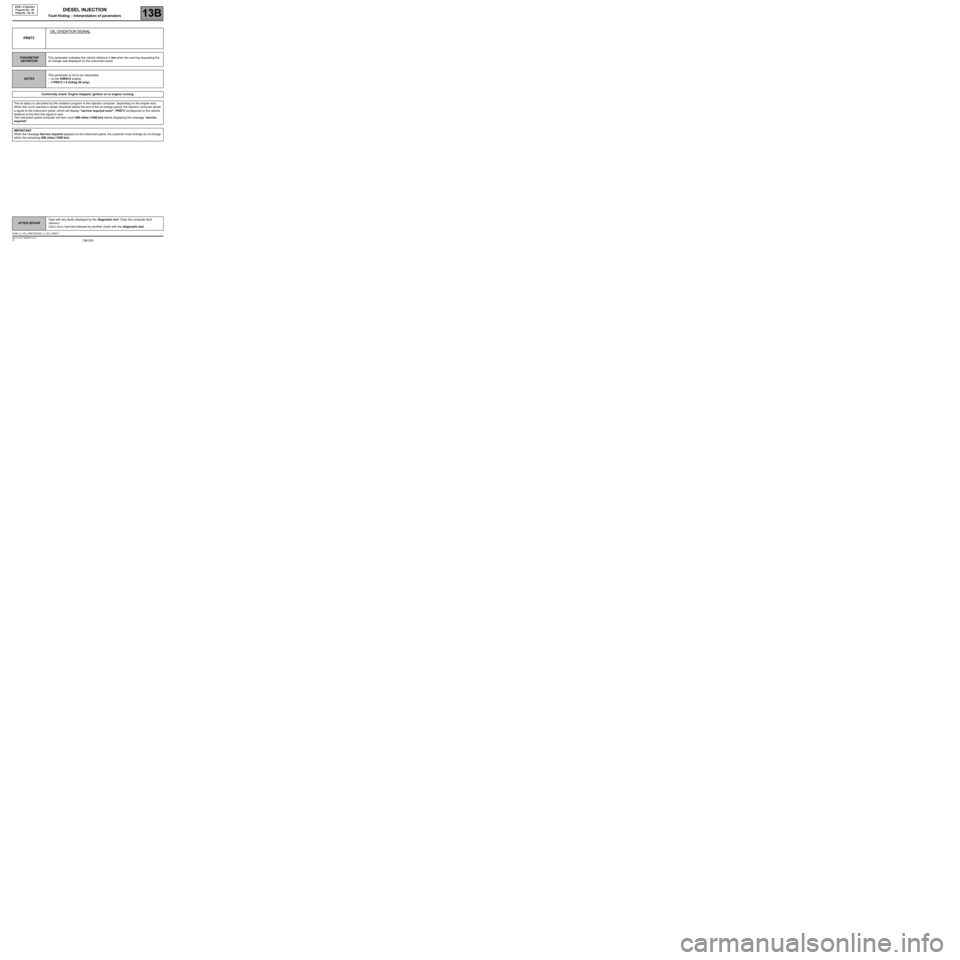
PR873OIL OXIDATION SIGNAL
PARAMETER
DEFINITIONThis parameter indicates the vehicle distance in km when the warning requesting the
oil change was displayed on the instrument panel.
NOTESThis parameter is not to be interpreted:
–on the K9K812 engine,
–if PR873 = 0 (Vdiag 58 only).
Conformity check: Engine stopped, ignition on or engine running.
The oil status is calculated by the oxidation program in the injection computer, depending on the engine revs.
When this count reaches a certain threshold before the end of the oil change period, the injection computer sends
a signal to the instrument panel, which will display "service required soon". PR873 corresponds to the vehicle
distance at the time this signal is sent.
The instrument panel computer will then count 900 miles (1500 km) before displaying the message "service
required".
IMPORTANT
When the message Service required appears on the instrument panel, the customer must arrange an oil change
within the remaining 900 miles (1500 km).
DCM1.2_V54_PR873/DCM1.2_V5C_PR873
Page 204 of 269
13B-204
AFTER REPAIRDeal with any faults displayed by the diagnostic tool. Clear the computer fault
memory.
Carry out a road test followed by another check with the diagnostic tool.
V6 MR-413-X44-13B000$170.mif
DIESEL INJECTION
Fault finding – Interpretation of parameters13B
DCM 1.2 Injection
Program No.: 4D
Vdiag No.: 54, 5C
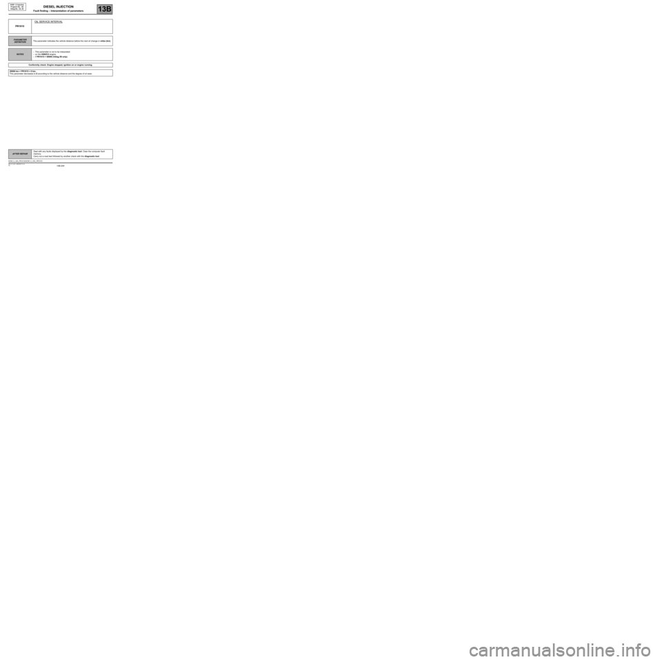
PR1015OIL SERVICE INTERVAL
PARAMETER
DEFINITIONThis parameter indicates the vehicle distance before the next oil change in miles (km).
NOTES–This parameter is not to be interpreted:
–on the K9K812 engine,
–if PR1015 = 50000 (Vdiag 58 only).
Conformity check: Engine stopped, ignition on or engine running.
20000 km < PR1015 < 0 km.
This parameter decreases to 0 according to the vehicle distance and the degree of oil wear.
DCM1.2_V54_PR1015/DCM1.2_V5C_PR1015