rear view mirror RENAULT TWINGO 2009 2.G Heating And Air Conditioning - Climate Control Workshop Manual
[x] Cancel search | Manufacturer: RENAULT, Model Year: 2009, Model line: TWINGO, Model: RENAULT TWINGO 2009 2.GPages: 99
Page 9 of 99

62B-9
MR-413-X44-62B000$092_eng.mif
V1
CLIMATE CONTROL
Fault finding - List and location of components
Vdiag No.: 44
62B
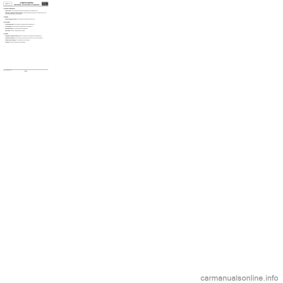
●HEATING COMPONENTS
–Heater matrix: This is located at the bottom of the heating and air conditioning unit.
–Passenger compartment heating resistors: These are located at the bottom of the heater matrix on the
driver's side (depending on the equipment).
●SENSOR
–Interior temperature sensor: This is located on the interior rear-view mirror.
●ACTUATORS
–Air distribution flap: This is located in the heating and air conditioning unit.
–Air mixing flap: This is located in the heating and air conditioning unit.
–Recirculation flap: This is located behind the dashboard.
–Flap motors: These are located close to the flaps.
●OTHERS
–Passenger compartment blower unit: This is located in the heating and air conditioning unit.
–Cooling fan assembly: This is located in the front panel of the vehicle, in front of the condenser.
–Climate control computer: This is located in the control panel.
–Air pipes: Theses are located under the dashboard.
Page 19 of 99

62B-19
MR-413-X44-62B000$230_eng.mif
V1
Vdiag No.: 44CLIMATE CONTROL
Fault finding - Function62B
Vehicle
multiplex
network
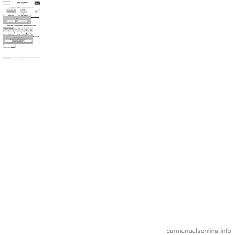
Summary diagram of components controlled or managed by the UCH:
Summary diagram of components controlled or managed by the injection computer Rear screen de-icing and
rear-view mirror de-icer
(depending on version)External
temperature sensor
(depending on
version)
Actuator control Sensor management
UCH
Air conditioning request
managementHeated rear screen control
management
Relay No. 1 for
the Passenger
Compartment
Heating
ResistorsRelay No. 2 for
the Passenger
Compartment
Heating
ResistorsAir conditioning
compressorEngine cooling
fan assemblyEngine
coolant
temperature
sensorRefrigerant
fluid
pressure
sensor
Actuator control Sensor management
Engine injection computer
Management of the cold loop (refrigerant pressure,
engine cooling fan activation request,
compressor activation authorisation, etc.)
Key:
Wire connections =
Multiplex connections =
Page 26 of 99

62B-26
MR-413-X44-62B000$414_eng.mif
V1
CLIMATE CONTROL
Fault finding - Interpretation of faults
Vdiag No.: 44
62B
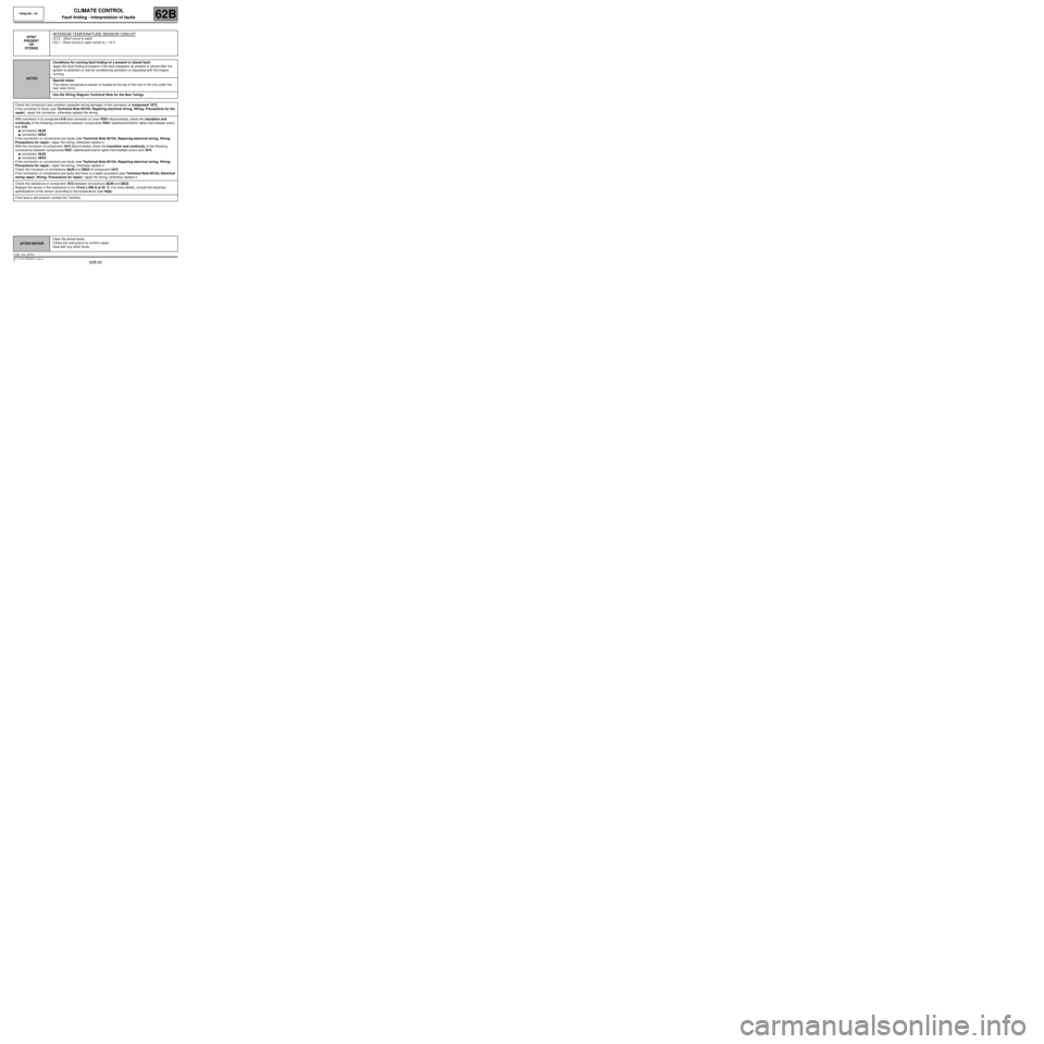
DF007
PRESENT
OR
STOREDINTERIOR TEMPERATURE SENSOR CIRCUIT
CC.0 : Short circuit to earth
CO.1 : Short circuit or open circuit to + 12 V
NOTESConditions for running fault finding on a present or stored fault:
Apply this fault finding procedure if the fault reappears as present or stored after the
ignition is switched on and air conditioning activation is requested with the engine
running.
Special notes:
The interior temperature sensor is located at the top of the roof in the unit under the
rear view mirror.
Use the Wiring Diagram Technical Note for the New Twingo.
Check the connection and condition (possible wiring damage) of the connector of component 1872.
If the connector is faulty (see Technical Note 6015A, Repairing electrical wiring, Wiring: Precautions for the
repair), repair the connector, otherwise replace the wiring.
With connector A of component 419 and connector of union R301 disconnected, check the insulation and
continuity of the following connections between components R301 (dashboard/interior lights intermediate union)
and 419.
●connection 38JN
●connection 38GZ
If the connection or connections are faulty (see Technical Note 6015A, Repairing electrical wiring, Wiring:
Precautions for repair), repair the wiring, otherwise replace it.
With the connector of component 1872 disconnected, check the insulation and continuity of the following
connections between components R301 (dashboard/interior lights intermediate union) and 1872.
●connection 38JN
●connection 38GZ
If the connection or connections are faulty (see Technical Note 6015A, Repairing electrical wiring, Wiring:
Precautions for repair), repair the wiring, otherwise replace it.
Check the insulation of connections 38JN and 38GZ of component 1872.
If the connection or connections are faulty and there is a repair procedure (see Technical Note 6015A, Electrical
wiring repair, Wiring: Precautions for repair), repair the wiring, otherwise replace it.
Check the resistance of component 1872 between connections 38JN and 38GZ.
Replace the sensor if the resistance is not 10 kΩΩ Ω Ω
± 500 ΩΩ Ω Ω
at 25 ˚C. For more details, consult the electrical
specifications of the sensor according to the temperature (see Help).
If the fault is still present, contact the Techline.
AFTER REPAIRClear the stored faults.
Follow the instructions to confirm repair.
Deal with any other faults.
CLIM_V44_DF007
Page 89 of 99

62B-89
MR-413-X44-62B000$920_eng.mif
V1
62B
CLIMATE CONTROL
Diagnostic - Fault finding chart
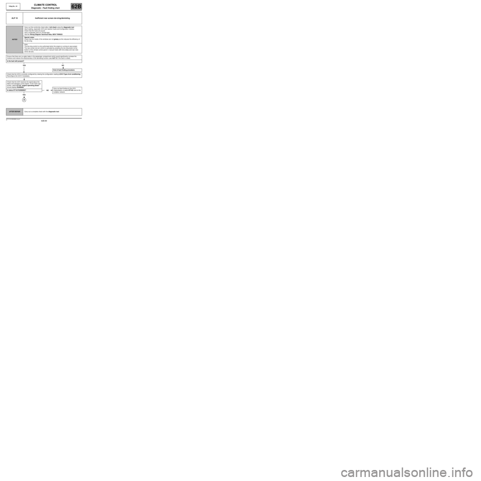
ALP 10 Inefficient rear screen de-icing/demisting
NOTESCarry out this conformity check after a full check using the diagnostic tool
(fault reading, especially UCH and injection faults and configuration checks).
Check that the fuses are sound.
Use a multimeter and a 21 W test light.
Use the Wiring Diagram Technical Note, NEW TWINGO.
Special notes:
Check that the inside of the windows are not greasy as this reduces the efficiency of
the de-icing.
Note:
The de-icing control is only authorised when the engine is running to save power.
The rear screen de-icer control is activated by pressing the de-icing button at the
bottom of the climate control panel in manual mode (with time delay and rear-view
mirror de-icer).
Ensure that there are no water leaks in the passenger compartment which would significantly increase the
moisture and reduce the effectiveness of the demisting function (see ALP 12 if the fault is noted).
Is the fault still present?
YES NO
Check that the UCH is correctly configured by viewing the configuration reading LC013 Type of air conditioning.
Reconfigure the UCH if necessary.
Check that the UCH receives the signal about the
status and operation of the engine. In the Cold Loop
screen, status ET142 "engine operating phase"
should display RUNNING.
Is status ET142 RUNNING?
YES
End of fault finding procedure.
NOCarry out fault finding on the UCH
(interpretation of status ET142) and on the
multiplex network.
AFTER REPAIRCarry out a complete check with the diagnostic tool.
Vdiag No.: 44
MR-413-X44-62B000$920_eng.mif