technical specifications RENAULT TWINGO 2009 2.G Heating And Air Conditioning - Climate Control Workshop Manual
[x] Cancel search | Manufacturer: RENAULT, Model Year: 2009, Model line: TWINGO, Model: RENAULT TWINGO 2009 2.GPages: 99
Page 1 of 99

Heating and
air conditioning system
"The repair procedures given by the manufacturer in this document are based on the
technical specifications current when it was prepared.
The procedures may be modified as a result of changes introduced by the
manufacturer in the production of the various component units and accessories from
which his vehicles are constructed."
V1
All rights reserved by Renault s.a.s.
Edition Anglaise
Copying or translating, in part or in full, of this document or use of the service part
reference numbering system is forbidden without the prior written authority of
Renault s.a.s.
© Renault s.a.s.
V1 MR-413-X44-62B000$000_engTOC.mif
CLIMATE CONTROL
Vdiag No.: 44
Fault finding - Introduction 62B - 2
Fault finding - List and location of components 62B - 8
Fault finding - Role of components 62B - 10
Fault finding - Operating diagram 62B - 16
Fault finding - Function 62B - 17
Fault finding - Replacement of components 62B - 21
Fault finding - Configuration and programming 62B - 22
Fault finding - Fault summary table 62B - 24
Fault finding - Interpretation of faults 62B - 25
Fault finding - Conformity check 62B - 32
Fault finding - Status summary table 62B - 42
Fault finding - Interpretation of statuses 62B - 45
Fault finding - Interpretation of parameters 62B - 52
Fault finding - Command summary table 62B - 61
Fault finding - Interpretation of commands 62B - 62
Fault finding - Customer complaints 62B - 66
Diagnostic - Fault finding chart 62B - 68
Fault finding - Help 62B - 96
62B
MR-413-X44-62B000$000_engTOC.mif
Page 2 of 99

62B-2
MR-413-X44-62B000$046_eng.mif
V1
62B
CLIMATE CONTROL
Fault finding - Introduction
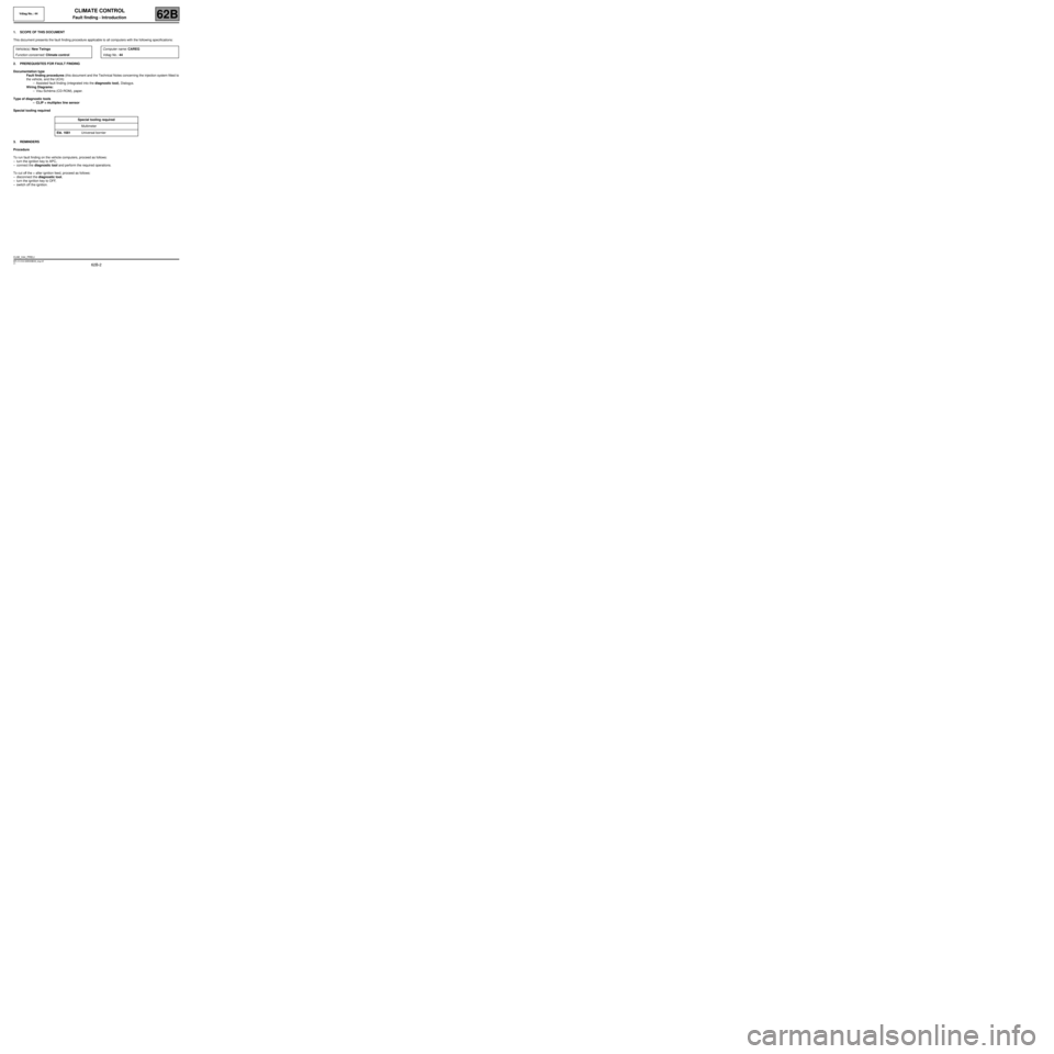
1. SCOPE OF THIS DOCUMENT
This document presents the fault finding procedure applicable to all computers with the following specifications:
2. PREREQUISITES FOR FAULT FINDING
Documentation type
Fault finding procedures (this document and the Technical Notes concerning the injection system fitted to
the vehicle, and the UCH):
–Assisted fault finding (integrated into the diagnostic tool), Dialogys.
Wiring Diagrams:
–Visu-Schéma (CD-ROM), paper.
Type of diagnostic tools
–CLIP + multiplex line sensor
Special tooling required
3. REMINDERS
Procedure
To run fault finding on the vehicle computers, proceed as follows:
–turn the ignition key to APC,
–connect the diagnostic tool and perform the required operations.
To cut off the + after ignition feed, proceed as follows:
–disconnect the diagnostic tool,
–turn the ignition key to OFF,
–switch off the ignition. Vehicle(s): New Twingo
Function concerned: Climate controlComputer name: CAREG
Vdiag No.: 44
Special tooling required
Multimeter
Elé. 1681 Universal bornier
CLIM_V44_PRELI
Vdiag No.: 44
MR-413-X44-62B000$046_eng.mif
Page 26 of 99

62B-26
MR-413-X44-62B000$414_eng.mif
V1
CLIMATE CONTROL
Fault finding - Interpretation of faults
Vdiag No.: 44
62B
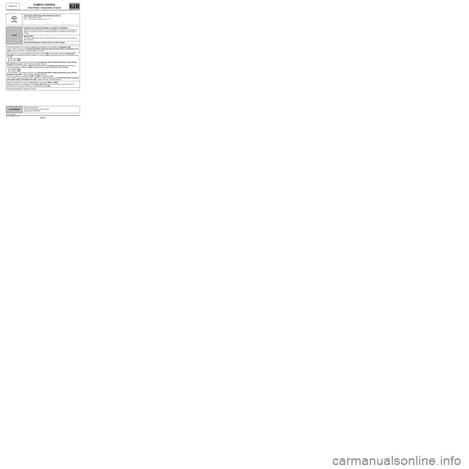
DF007
PRESENT
OR
STOREDINTERIOR TEMPERATURE SENSOR CIRCUIT
CC.0 : Short circuit to earth
CO.1 : Short circuit or open circuit to + 12 V
NOTESConditions for running fault finding on a present or stored fault:
Apply this fault finding procedure if the fault reappears as present or stored after the
ignition is switched on and air conditioning activation is requested with the engine
running.
Special notes:
The interior temperature sensor is located at the top of the roof in the unit under the
rear view mirror.
Use the Wiring Diagram Technical Note for the New Twingo.
Check the connection and condition (possible wiring damage) of the connector of component 1872.
If the connector is faulty (see Technical Note 6015A, Repairing electrical wiring, Wiring: Precautions for the
repair), repair the connector, otherwise replace the wiring.
With connector A of component 419 and connector of union R301 disconnected, check the insulation and
continuity of the following connections between components R301 (dashboard/interior lights intermediate union)
and 419.
●connection 38JN
●connection 38GZ
If the connection or connections are faulty (see Technical Note 6015A, Repairing electrical wiring, Wiring:
Precautions for repair), repair the wiring, otherwise replace it.
With the connector of component 1872 disconnected, check the insulation and continuity of the following
connections between components R301 (dashboard/interior lights intermediate union) and 1872.
●connection 38JN
●connection 38GZ
If the connection or connections are faulty (see Technical Note 6015A, Repairing electrical wiring, Wiring:
Precautions for repair), repair the wiring, otherwise replace it.
Check the insulation of connections 38JN and 38GZ of component 1872.
If the connection or connections are faulty and there is a repair procedure (see Technical Note 6015A, Electrical
wiring repair, Wiring: Precautions for repair), repair the wiring, otherwise replace it.
Check the resistance of component 1872 between connections 38JN and 38GZ.
Replace the sensor if the resistance is not 10 kΩΩ Ω Ω
± 500 ΩΩ Ω Ω
at 25 ˚C. For more details, consult the electrical
specifications of the sensor according to the temperature (see Help).
If the fault is still present, contact the Techline.
AFTER REPAIRClear the stored faults.
Follow the instructions to confirm repair.
Deal with any other faults.
CLIM_V44_DF007