climate control RENAULT TWINGO 2009 2.G Heating And Air Conditioning - Heating Workshop Manual
[x] Cancel search | Manufacturer: RENAULT, Model Year: 2009, Model line: TWINGO, Model: RENAULT TWINGO 2009 2.GPages: 29
Page 19 of 29
61A-19
MR-413-X44-61A000$875_eng.mif
V1
61A
HEATING
Fault finding - Fault finding charts
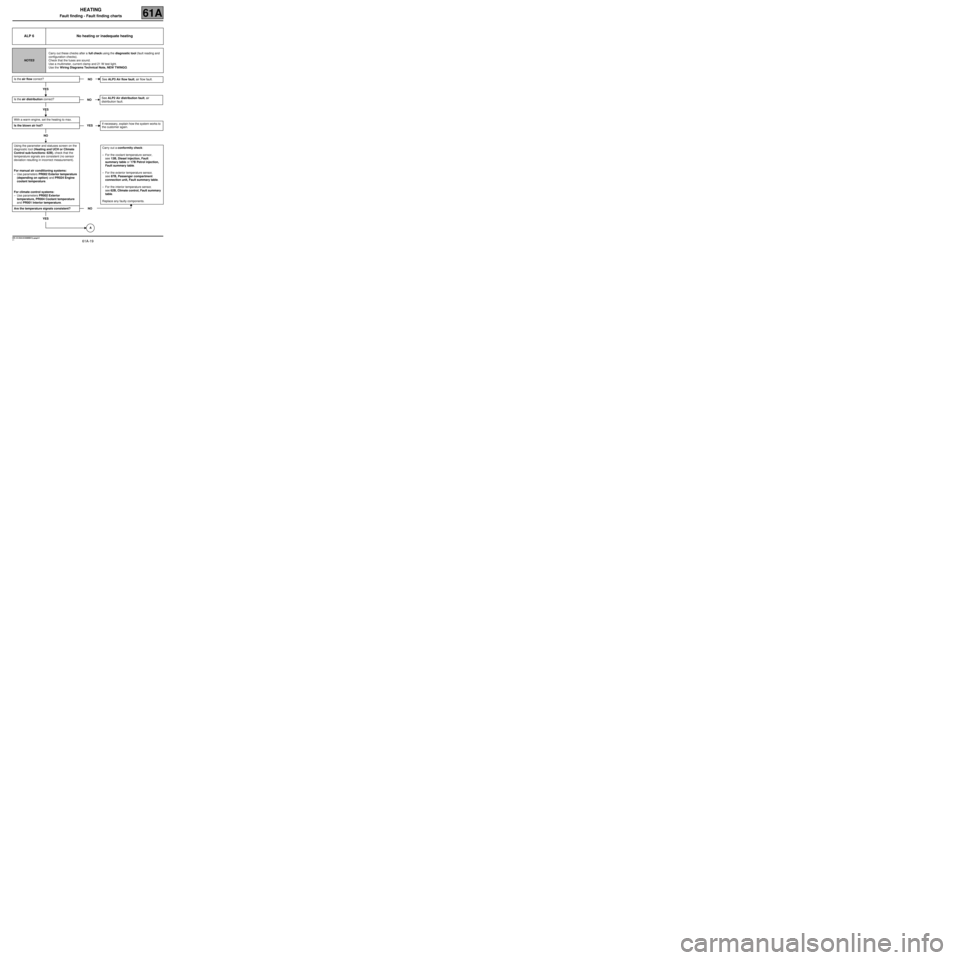
ALP 6 No heating or inadequate heating
NOTESCarry out these checks after a full check using the diagnostic tool (fault reading and
configuration checks).
Check that the fuses are sound.
Use a multimeter, current clamp and 21 W test light.
Use the Wiring Diagrams Technical Note, NEW TWINGO.
Is the air flow correct?
YES
Is the air distribution correct?
YES
With a warm engine, set the heating to max.
Is the blown air hot?
NO
Using the parameter and statuses screen on the
diagnostic tool (Heating and UCH or Climate
Control sub-functions: 62B), check that the
temperature signals are consistent (no sensor
deviation resulting in incorrect measurement).
For manual air conditioning systems:
–Use parameters PR002 Exterior temperature
(depending on option) and PR024 Engine
coolant temperature.
For climate control systems:
–Use parameters PR002 Exterior
temperature, PR004 Coolant temperature
and PR001 Interior temperature.
Are the temperature signals consistent?
YES
NOSee ALP3 Air flow fault, air flow fault.
NOSee ALP2 Air distribution fault, air
distribution fault.
YESIf necessary, explain how the system works to
the customer again.
Carry out a conformity check:
–For the coolant temperature sensor,
see 13B, Diesel injection, Fault
summary table or 17B Petrol injection,
Fault summary table.
–For the exterior temperature sensor,
see 87B, Passenger compartment
connection unit, Fault summary table.
–For the interior temperature sensor,
see 62B, Climate control, Fault summary
table.
Replace any faulty components.
NO
A
MR-413-X44-61A000$875_eng.mif
Page 20 of 29
61A-20
MR-413-X44-61A000$875_eng.mif
V1
HEATING
Fault finding - Fault finding charts61A
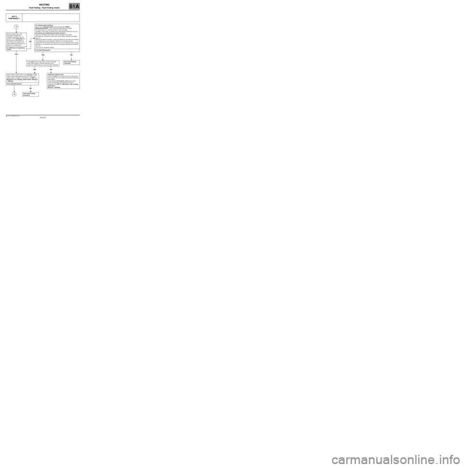
ALP 6
CONTINUED 1
With the engine warm and
passenger compartment
ventilation operating, vary the
position of the mixing flap from
the maximum cold position to
the maximum hot position and
check subjectively that there is a
dif ference in temperature.
Is a difference in temperature
noted?
YES
NO
For climate control systems:
Carry out a conformity check on the mixing motor (PR012
Mixing flap position). If the conformity check does not reveal
any faults, look for a mechanical fault on the mixing flap
(condition of the motor ’s notched sector, flap jammed inside the unit, etc.).
For manual air conditioning and heater versions:
Check the condition and routing of the mixing flap control cable.
Eliminate any constraints it may have such as kinks, restriction by plastic
clips, etc.
Replace the lead if necessary. Unclip the cable from the side of the heating/
air conditioning unit and check the stiffness of movement of each
component: control button and flap control on the air distribution unit. Check
that there is no mechanical fault with the mixing flap (flap jammed inside the
unit, etc.).
Carry out any necessary repairs.
Is the fault still present?
YES NO
Is the lower heater matrix pipe (coolant inlet) hot?
Note: Pipe located on the left-hand side of the
heater-air conditioning unit, near the engine bulkhead.
YES NO
End of fault finding
procedure.
Check that the heater matrix is not blocked: the top
heater matrix outlet pipe should be hot. Clean the
heater matrix or replace it if necessary (see MR 411,
Mechanical, 61A, Heating, Heater matrix: Removal
- Refitting).
Is the fault still present?
NO
Check the coolant circuit:
Check the level of the coolant circuit (too low a level
may unprime the circuit when driving at low loads and
when idling).
Check that the thermostatic valve opens at the
correct temperature, and replace the valve if
necessary (see MR 411, Mechanical, 19A, cooling,
thermostat:
Removal - Refitting).
End of fault finding
procedure.
A
B
Page 21 of 29
61A-21
MR-413-X44-61A000$875_eng.mif
V1
HEATING
Fault finding - Fault finding charts61A
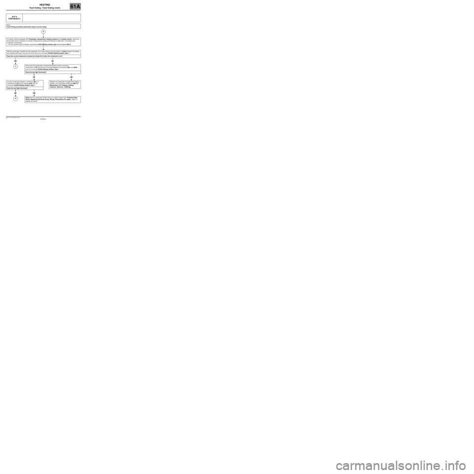
ALP 6
CONTINUED 2
Note:
Fault finding procedure performed using a current clamp.
For diesel vehicles equipped with Passenger compartment heating resistors and climate control, check that
the climate control computer is correctly configured by reading the following configuration (reconfigure the
computer if necessary):
–For the climate control computer, parameter LC044 Heating resistor type should display 900 W.
With the passenger compartment fan activated, fit a current clamp to the connection of earth between the battery
and chassis earth point, and use the CLIP tool to run command AC250 Heating resistor relay 1.
Does the current measured increase by at least 20 A when the command is run?
YES NO
Connect a test light between connection 38LL of
component 1113 and the chassis earth and run
command AC250 Heating resistor relay 1.
Does the test light illuminate?
NO YES
Disconnect the passenger compartment heating resistor connector
(component 1113) and connect a test light between connections 38LL and MAK
and run command AC250 Heating resistor relay 1.
Does the test light illuminate?
NO YES
Replace the passenger compartment heating
resistor unit (component 1113) (see MR 411,
Mechanical, 61A, Heating, Heating
resistors: Removal - Refitting).
Earth fault on component 1113. If there is a repair method (see Technical Note
6015A, Repairing electrical wiring, W iring: Precautions for repair), repair or
replace the wiring.
B
C
D
Page 24 of 29
61A-24
MR-413-X44-61A000$875_eng.mif
V1
HEATING
Fault finding - Fault finding charts61A
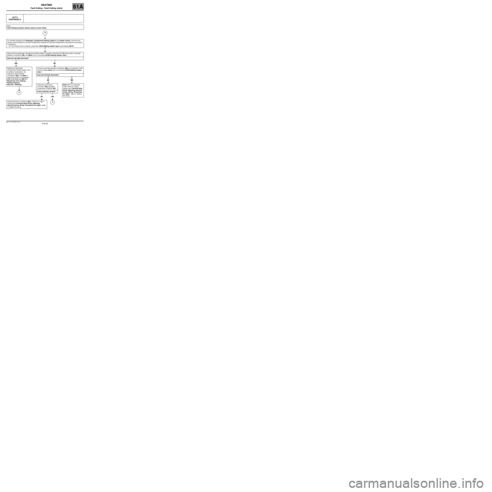
ALP 6
CONTINUED 5
Note:
Fault finding procedure without using a current clamp.
For vehicles equipped with Passenger compartment heating resistors and climate control, check that the
climate control computer is correctly configured by reading the following configurations (reconfigure the computer
if necessary):
–For the climate control computer, parameter LC044 Heating resistor type should display 900 W.
Disconnect the passenger compartment heating resistor connector (component 1113) and connect a test light
between connections 38LL and MAK and run command AC250 Heating resistor relay 1.
Does the test light illuminate?
YES NO
Replace the passenger
compartment heating resistor unit if,
at ambient temperature, the
resistance value between
connections 38LL and MAK of
component 1113, is not between:
0.55 and 0.75 ΩΩ Ω Ω
(see MR 411,
Mechanical, 61A, Heating,
Heating resistors:
Removal - Refitting).
Connect a test light between connections 38LL of component 1113
and the chassis earth and run command AC250 Heating resistor
relay 1.
Does the test bulb illuminate?
NO YES
Earth fault on component
1113. If there is a repair
method (see Technical Note
6015A, Repairing electrical
wiring, Wiring: Precautions
for repair), repair or replace
the wiring.
B
Check the continuity on
connection 38LL between
components 1113 and 1067.
Is the continuity correct?
NO YES
Continuity fault on connection 38LL. If there is a repair
method (see Technical Note 6015A, Repairing
electrical wiring, Wiring: Precautions for repair), repair
or replace the wiring.D
C
Page 27 of 29
61A-27
MR-413-X44-61A000$875_eng.mif
V1
HEATING
Fault finding - Fault finding charts61A
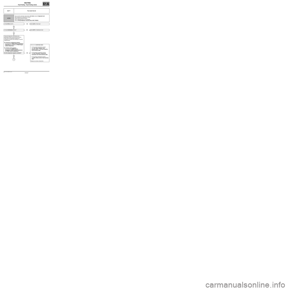
ALP 7 Too much hot air
NOTESCarry out this conformity check after a full check using the diagnostic tool
(fault reading and configuration checks).
Check that the fuses are sound.
Use a multimeter and a 21 W test light.
Use the Wiring Diagrams Technical Note, NEW TWINGO.
Is the air flow correct?
YES
Is the air distribution correct?
YES
Using the diagnostic tool statuses and
parameters screen (cold loop sub-function),
check that the temperature signals are
consistent (no sensor drift resulting in incorrect
measurement).
For manual air conditioning systems:
–Use parameters PR002 Exterior temperature
(depending on version) and PR024 Engine
coolant temperature.
For climate control systems:
–Use parameters PR002 Exterior
temperature, PR004 Coolant temperature
and PR001 Interior temperature.
Are the temperature signals consistent?
YES
NOSee ALP3, Air flow fault
NOSee ALP2, Air distribution fault.
NOCarry out a conformity check:
–For the coolant temperature sensor,
see 13B, Diesel injection, Fault
summary table or 17B Petrol injection,
Fault summary table.
–For the exterior temperature sensor,
see 87B, Passenger compartment
connection unit, Fault summary table.
–For the interior temperature sensor,
see 62B, Climate control, Fault summary
table.
Replace any faulty components.
A
Page 28 of 29
61A-28
MR-413-X44-61A000$875_eng.mif
V1
HEATING
Fault finding - Fault finding charts61A
ALP 7
CONTINUED 1
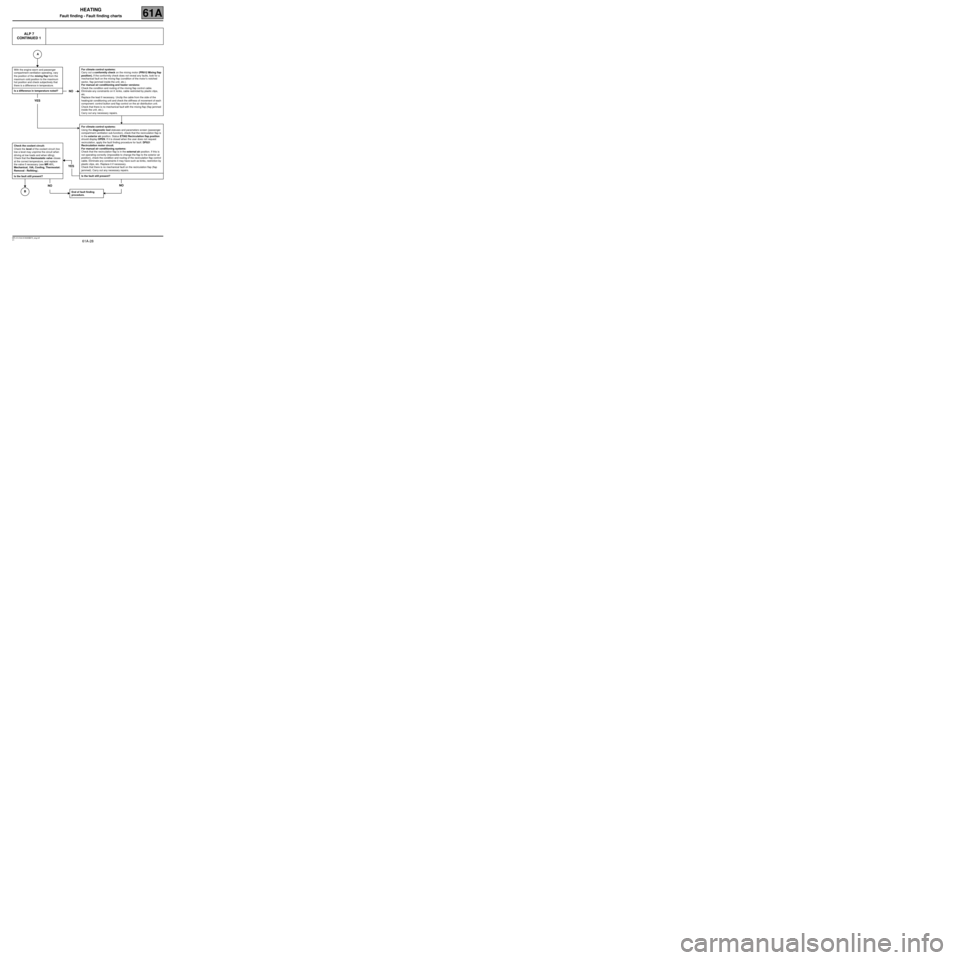
With the engine warm and passenger
compartment ventilation operating, vary
the position of the mixing flap from the
maximum cold position to the maximum
hot position and check subjectively that
there is a difference in temperature.
Is a difference in temperature noted?
YES
NO
For climate control systems:
Carry out a conformity check on the mixing motor (PR012 Mixing flap
position). If the conformity check does not reveal any faults, look for a
mechanical fault on the mixing flap (condition of the motor’s notched
sector, flap jammed inside the unit, etc.).
For manual air conditioning and heater versions:
Check the condition and routing of the mixing flap control cable.
Eliminate any constraints on it: kinks, cable restricted by plastic clips,
etc.
Replace the lead if necessary. Unclip the cable from the side of the
heating/air conditioning unit and check the stiffness of movement of each
component: control button and flap control on the air distribution unit.
Check that there is no mechanical fault with the mixing flap (flap jammed
inside the unit, etc.).
Carry out any necessary repairs.
YES
For climate control systems:
Using the diagnostic tool statuses and parameters screen (passenger
compartment ventilation sub-function), check that the recirculation flap is
in the exterior air position. Status ET062 Recirculation flap position
should display OPEN. If it is closed when the user does not request
recirculation, apply the fault finding procedure for fault: DF021
Recirculation motor circuit.
For manual air conditioning systems:
Check that the recirculation flap is in the external air position. If this is
not operating correctly (impossible to change the flap to the exterior air
position), check the condition and routing of the recirculation flap control
cable. Eliminate any constraints it may have such as kinks, restriction by
plastic clips, etc. Replace it if necessary.
Check that there is no mechanical fault on the recirculation flap (flap
jammed). Carry out any necessary repairs.
Is the fault still present?
NO
End of fault finding
procedure.
Check the coolant circuit:
Check the level of the coolant circuit (too
low a level may unprime the circuit when
driving at low loads and when idling).
Check that the thermostatic valve closes
at the correct temperature, and replace
the valve if necessary (see MR 411,
Mechanical, 19A, Cooling, Thermostat:
Removal - Refitting).
Is the fault still present?
NO
A
B