torque RENAULT TWINGO 2009 2.G Mechanism And Accessories Workshop Manual
[x] Cancel search | Manufacturer: RENAULT, Model Year: 2009, Model line: TWINGO, Model: RENAULT TWINGO 2009 2.GPages: 95
Page 4 of 95
51A-1
SIDE OPENING ELEMENT MECHANISMS
Front side door lock: Removal - Refitting
51A
REMOVAL
I - REMOVAL PREPARATION OPERATION
aRemove:
-the front side door trim (see Front side door trim:
Removal - Refitting) (MR 412, 72A, Side opening
element trim),
-the door sealing film (see Door sealing film: Re-
moval - Refitting) (MR 412, 65A, Opening ele-
ment sealing),
-the door exterior handle (see 51A, Side opening
element mechanisms, Exterior door handle:
Removal - Refitting, page 51A-5) .
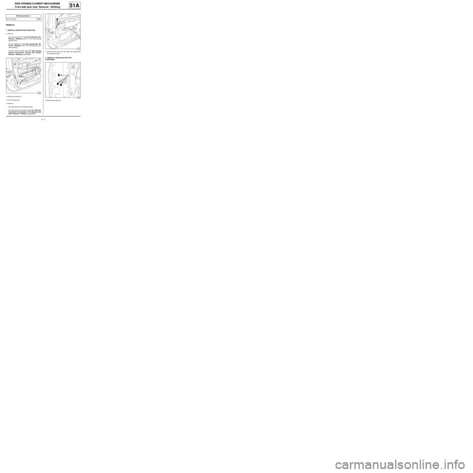
aRemove the bolts (1) .
aUndo the bolts (2) .
aRemove:
-the lower guide on the sliding window,
-the front side door lock barrel (see 51A, Side ope-
ning element mechanisms, Front side door lock
barrel: Removal - Refitting, page 51A-3) .aUndo the front side door lock catch (3) (depending
on equipment level).
II - REMOVAL OPERATION FOR PART
CONCERNED
aRemove the bolts (4) . Tightening torquesm
door lock bolts8 Nm
119278
121218
119256
Page 5 of 95

51A-2
SIDE OPENING ELEMENT MECHANISMS
Front side door lock: Removal - Refitting
51A
aGently lift the door lock to extract it from the retaining
hook (5) .
aUnclip the interior locking linkage on the door lock
(depending on equipment level).
aDisconnect the door lock supply connector (depen-
ding on equipment level).
aRemove the lock from the door box section.
REFITTING
I - REFITTING OPERATION FOR PART
CONCERNED
aPosition the sealing foam on the lock (depending on
equipment level) (part no. 82 00 556 180).
aFit the lock into the door box section.
aClip the interior locking linkage onto the door lock
(depending on equipment level).
aPosition the door lock on the retaining hook (5) .
aConnect the door lock supply connector (depending
on equipment level).
aRefit the bolts (4) without tightening them.aTorque tighten the door lock bolts (8 Nm) following
the tightening order:
-bolt (5) ,
-bolt (6) ,
-bolt (7) .
aCarry out a function test.
II - FINAL OPERATION.
aFit the front side door lock catch (3) .
aRefit:
-the front side door lock barrel (see 51A, Side ope-
ning element mechanisms, Front side door lock
barrel: Removal - Refitting, page 51A-3) ,
-the lower guide on the sliding window,
-the bolts (1) .
aTighten the bolts (2) .
aRefit:
-the door exterior handle (see 51A, Side opening
element mechanisms, Exterior door handle:
Removal - Refitting, page 51A-5) ,
-the door sealing film (see Door sealing film: Re-
moval - Refitting) (MR 412, 65A, Opening ele-
ment sealing),
-the front side door trim (see Front side door trim:
Removal - Refitting) (MR412, 72A, Side opening
elements trim).
18696119256
Page 9 of 95

51A-6
SIDE OPENING ELEMENT MECHANISMS
Front side door electric window mechanism: Removal - Refitting51A
REMOVAL
I - REMOVAL PREPARATION OPERATION
aRemove:
-the front side door trim (see Front side door trim:
Removal - Refitting) (MR 412, 72A, Side opening
element trim),
-the door sealing film (see Door sealing film: Re-
moval - Refitting) (MR 412, 65A, Opening ele-
ment sealing),
-the front side sliding door window (see 54A, Win-
dows, Front side door sliding window: Removal
- Refitting, page 54A-3) or keep it in the raised po-
sition with masking tape.
II - REMOVAL OPERATION FOR PART
CONCERNED
aRemove:
-the bolts (1) ,
-the bolts (2) .
aDisconnect the window winder mechanism supply
connector.
aRemove the window lift mechanism.
REFITTING
I - REFITTING OPERATION FOR PART
CONCERNED
aRefit the window lift mechanism.
aConnect the window winder mechanism supply con-
nector.
aRefit:
-the window winder mechanism bolts without tighte-
ning them,
-the front side sliding door window (see 54A, Win-
dows, Front side door sliding window: Removal
- Refitting, page 54A-3) or keep it in the raised po-
sition with masking tape.
a
aTorque tighten the electric window winder mecha-
nism bolts ( 6.5 Nm) following the tightening order:
-bolt (3) ,
-bolt (4) ,
-bolt (5) .
aCarry out a function test. Tightening torquesm
electr ic window winder
mechanism bolts6.5 Nm
119280
119280
Note:
When refitting the window winder mechanism,
follow the tightening order of the bolts.
The tightening order ensures the window winder
mechanism is correctly aligned.
Page 11 of 95
51A-8
SIDE OPENING ELEMENT MECHANISMS
Front side door manual window winder mechanism: Removal - Refitting51A
REMOVAL
I - REMOVAL PREPARATION OPERATION
aRemove:
-the front side door trim (see Front side door trim:
Removal - Refitting) (MR 412, 72A, Side opening
element trim),
-the door sealing film (see Door sealing film: Re-
moval - Refitting) (MR 412, 65A, Opening ele-
ment sealing),
-the front side sliding door window (see 54A, Win-
dows, Front side door sliding window: Removal
- Refitting, page 54A-3) or keep it in the raised po-
sition with masking tape.
II - REMOVAL OPERATION FOR PART
CONCERNED
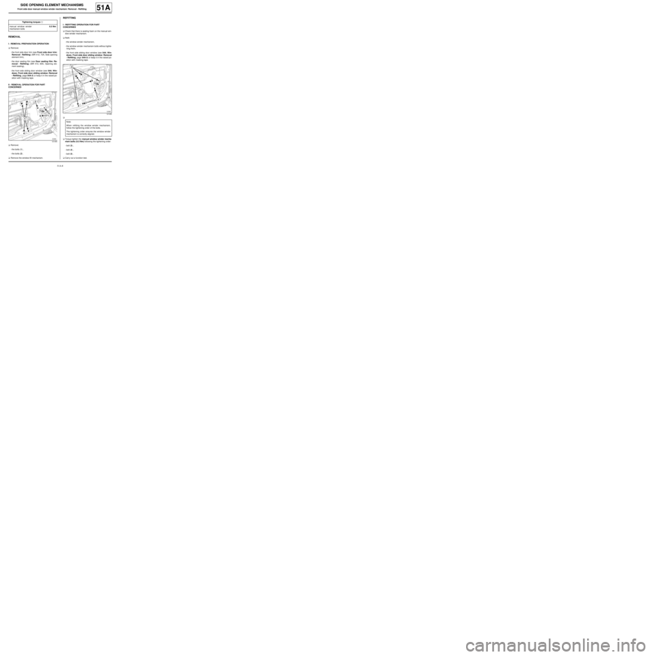
aRemove:
-the bolts (1) ,
-the bolts (2) .
aRemove the window lift mechanism.
REFITTING
I - REFITTING OPERATION FOR PART
CONCERNED
aCheck that there is sealing foam on the manual win-
dow winder mechanism.
aRefit:
-the window winder mechanism,
-the window winder mechanism bolts without tighte-
ning them,
-the front side sliding door window (see 54A, Win-
dows, Front side door sliding window: Removal
- Refitting, page 54A-3) or keep it in the raised po-
sition with masking tape.
a
aTorque tighten the manual window winder mecha-
nism bolts ( 6.5 Nm) following the tightening order:
-bolt (3) ,
-bolt (4) ,
-bolt (5) .
aCarry out a function test. Tightening torquesm
manual window winder
mechanism bolts6.5 Nm
121455
121455
Note:
When refitting the window winder mechanism,
follow the tightening order of the bolts.
The tightening order ensures the window winder
mechanism is correctly aligned.
Page 15 of 95

52A-1
NON-SIDE OPENING ELEMENT MECHANISMS
Bonnet lock: Removal - Refitting
52A
REMOVAL
I - REMOVAL PREPARATION OPERATION
aRemove the front bumper (see 55A, Exterior pro-
tection, Front bumper: Removal - Refitting, page
55A-1) .
II - OPERATION FOR REMOVAL OF PART
CONCERNED
aRemove:
-the bonnet catch nuts (1) through the openings (2)
in the front upper cross member,
-partially the bonnet catch.aUnclip:
-the clip (3) using a flat screwdriver,
-the bonnet opening cable sleeve stop (4) .
aRemove the bonnet catch.
REFITTING
I - REFITTING OPERATION FOR PART
CONCERNED
aClip on:
-the clip (3) ,
-the bonnet opening cable sleeve stop (4) .
aRefit:
-the bonnet catch,
-the bonnet catch nuts (1) .
aPretighten the bonnet catch nuts.
aAdjust the play and flush fitting of the bonnet ( (see
Bonnet: Adjustment) ).
aTorque tighten the bonnet catch nuts (21 Nm).
II - FINAL OPERATION.
aRefit the front bumper (see 55A, Exterior protec-
tion, Front bumper: Removal - Refitting, page
55A-1) . Tightening torquesm
bonnet catch nuts21 Nm
121039
121038
Page 17 of 95

52A-3
NON-SIDE OPENING ELEMENT MECHANISMS
Tailgate lock: Removal - Refitting
52A
REMOVAL
I - REMOVAL PREPARATION OPERATION
aRemove the tailgate trim ( (see Tailgate trim: Re-
moval - Refitting) ).
a
Unlock the tailgate lock by pushing lug (1) with a
screwdriver.II - OPERATION FOR REMOVAL OF PART
CONCERNED
aRemove:
-the bolts (2) from the boot lock,
-the lock from inside the tailgate.
aDisconnect the connector from the tailgate lock.
REFITTING
I - REFITTING OPERATION FOR PART
CONCERNED
aConnect the connector to the tailgate lock.
aRefit:
-the lock from inside the tailgate,
-the bolts (2) on the boot lock.
aTorque tighten the boot lock bolts (8 Nm ).
II - FINAL OPERATION.
aRefit the tailgate trim ( (see Tailgate trim: Removal
- Refitting) ). Tightening torquesm
boot lock bolts8 Nm100232
Note:
If there is an electrical fault it is possible to open
the tailgate manually.
Carry out this operation from inside the vehicle.
119288
Page 23 of 95
52A-9
NON-SIDE OPENING ELEMENT MECHANISMS
Sunroof mobile panel: Removal - Refitting
52A
REMOVAL
I - REMOVAL PREPARATION OPERATION
aOpen the sunroof.
aRemove:
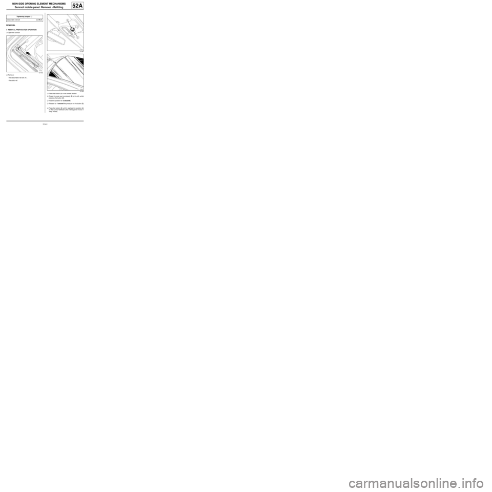
-the detachable rail bolt (1) ,
-the static rail.
aPress the button (2) in the central section.
aRotate the outer part completely (3) to the left, whilst
pressing the button (2) .
aHold this position for 3 seconds.
aRelease for 1 second the pressure on the button (2)
.
aPress the button (2) until it reaches the position (4)
on the sunroof deflector (the mobile panel moves in
“step” mode). Tightening torquesm
detachable rail bolt2.5 N.m
121492
121391
121493
Page 25 of 95
52A-11
NON-SIDE OPENING ELEMENT MECHANISMS
Sunroof mobile panel: Removal - Refitting
52A
aOpen the mobile panel ensuring the guide brackets
are inserted into the side rails of the sunroof opera-
ting mechanism.
III - FINAL OPERATION.
aRefit:
-the detachable rail,
-the detachable rail bolt (3) ,
aTorque tighten the detachable rail bolt (2.5 N.m).
aInitialise the sunroof motor (see Electric sunroof:
Initialisation) (MR 413, 87D, Electric windows - Su-
nroof).
109102
Note:
In the event that the sunroof mobile panel jams, it
is necessary to remove the headlining (see Hea-
dlining: Removal - Refitting) (MR 412, 71A,
Body internal trim).
Page 28 of 95
52A-14
NON-SIDE OPENING ELEMENT MECHANISMS
Sunroof deflector: Removal - Refitting
52A
REMOVAL
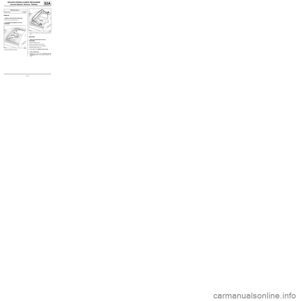
I - REMOVAL PREPARATION OPERATION
aOpen the sunroof mobile panel.
II - OPERATION FOR REMOVAL OF PART
CONCERNED
aRemove the deflector bolts (1) .aRemove the deflector by pivoting it (2) towards the
rear.
REFITTING
I - REFITTING OPERATION FOR PART
CONCERNED
aRefit the deflector at (2) .
aPosition the deflector return spring.
aKeep applying pressure to the deflector.
aRefit the deflector bolts (1) .
aTorque tighten the deflector bolts (2.5 Nm).
II - FINAL OPERATION.
aInitialise the sunroof motor (see Electric sunroof:
Initialisation) (MR 413, 87D, Electric windows - Su-
nroof). Tightening torquesm
deflector bolts2.5 Nm
121490
121491
Page 29 of 95

52A-15
NON-SIDE OPENING ELEMENT MECHANISMS
Sunroof sun visors: Removal - Refitting
PANORAMIC SUNROOF
52A
REMOVAL
I - REMOVAL PREPARATION OPERATION
aLock the airbag computer using the Diagnostic tool
(see Fault finding - Replacement of components)
(88C, Airbags and pretensioners).
aDisconnect the battery (see Battery: Removal - Re-
fitting) (80A, Battery).
aRemove the headlining (see Headlining: Removal -
Refitting) (71A, Body internal trim).II - OPERATION FOR REMOVAL OF PART
CONCERNED
aUnroll the sun visors fully.
aRemove the roof middle cross member bolts (2) .
aRemove the stops (3) .
aRoll the sun visors.
aRemove the « sunroof sun visors - roof centre cross
member » assembly.
REFITTING
I - REFITTING OPERATION FOR PART
CONCERNED
aBring together the « sunroof sun visors - roof centre
cross member » assembly.
aEngage the sun visors into the guide runners.
aUnroll the sun visors fully.
aRefit:
-the stops (3) ,
-the roof middle cross member bolts (2) .
aTorque tighten the roof middle cross member
bolts (4 N.m ). Equipment required
Diagnostic tool
Tightening torquesm
roof middle cross mem-
ber bolts4 N.m
IMPORTANT
To avoid any risk of triggering when working on or
near a pyrotechnic component (airbags or preten-
sioners), lock the airbag computer using the dia-
gnostic tool.
When this function is activated, all the trigger lines
are inhibited and the airbag warning light on the ins-
trument panel lights up contin uously (ignition on).
IMPORTANT
Never handle the pyrotechnic systems (pretensio-
ners or airbags) near to a source of heat or naked
flame - they may be triggered.
121222
Note:
Do not remove the bolts (1) from the visor retai-
ning yokes; the visors are connected to the mid-
dle cross member.