radiator RENAULT TWINGO 2009 2.G Panelwork Workshop Manual
[x] Cancel search | Manufacturer: RENAULT, Model Year: 2009, Model line: TWINGO, Model: RENAULT TWINGO 2009 2.GPages: 209
Page 2 of 209
TWINGO - Section 4
Contents
Pages
TWINGO - Section 4 ContentsPages
40A GENERAL INFORMATION
Specialised bodywork tools:
Use 40A-1
Vehicle on repair bench:
Description 40A-5
Subframe: Specifications 40A-7
Hollow section inserts: List
and location of components 40A-9
Hollow section inserts:
Precautions for the repair 40A-11
Earths on body: List and
location of components 40A-12
Vehicle structure, front
section: Description 40A-15
Vehicle structure, side
section: Description 40A-17
Vehicle structure, centre
section: Description 40A-19
Vehicle structure, rear
section: Description 40A-21
Vehicle structure, removable
section: Description 40A-23
Structural components to be
positioned on the repair
bench: Description 40A-25
Structural bodywork
documentation: Description 40A-2941A FRONT LOWER STRUCTURE
Front end lower cross
member: General description 41A-1
Front end lower cross
member: Description 41A-2
Radiator mounting cross
member: General description 41A-4
Radiator mounting cross
member: Removal - Refitting 41A-5
Front side member: General
descr iption 41A-6
Front side member, front
section: Description 41A-8
Front side member closure
panel, front section: General
descr iption 41A-11
Front side member closure
panel, front section:
Description 41A-13
Front side member, rear
section: Description 41A-15
Front subframe front
mounting: General
descr iption 41A-17
Front subframe front
mounting: Description 41A-18
Engine stand: General
descr iption 41A-20
Engine stand: Description 41A-21
Page 28 of 209
40A-23
GENERAL INFORMATION
Vehicle structure, removable section: Description
40A
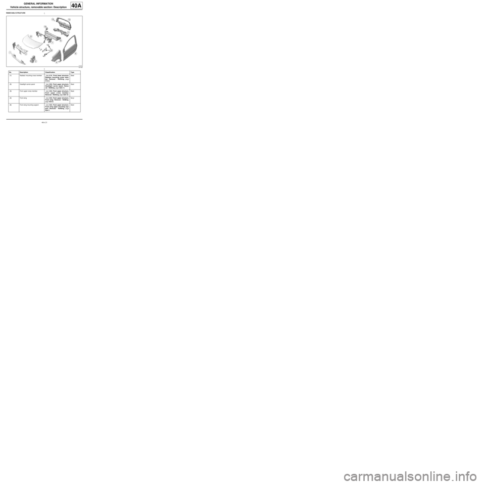
REMOVABLE STRUCTURE
121745
No. Description Classification Type
(1) Radiator mounting cross member (see 41A, Front lower structure,
Radiator mounting cross mem-
ber: Removal - Refitting, page
41A-5) Steel
(2) Headlight carrier panel (see 42A, Front upper structure,
Headlight carrier panel: Remo-
val - Refitting, page 42A-11) Steel
(3) Front upper cross member (see 42A, Front upper structure,
Front upper cross member:
Removal - Refitting, page 42A-13) Steel
(4) Front wing (see 42A, Front upper structure,
Front wing: Removal - Refitting,
page 42A-3) Noryl
(5) Front wing mounting support (see 42A, Front upper structure,
Front wing upper mounting sup-
port: Removal - Refitting, page
42A-7) Steel
Page 32 of 209
40A-27
GENERAL INFORMATION
Structural components to be positioned on the repair bench: Description40A
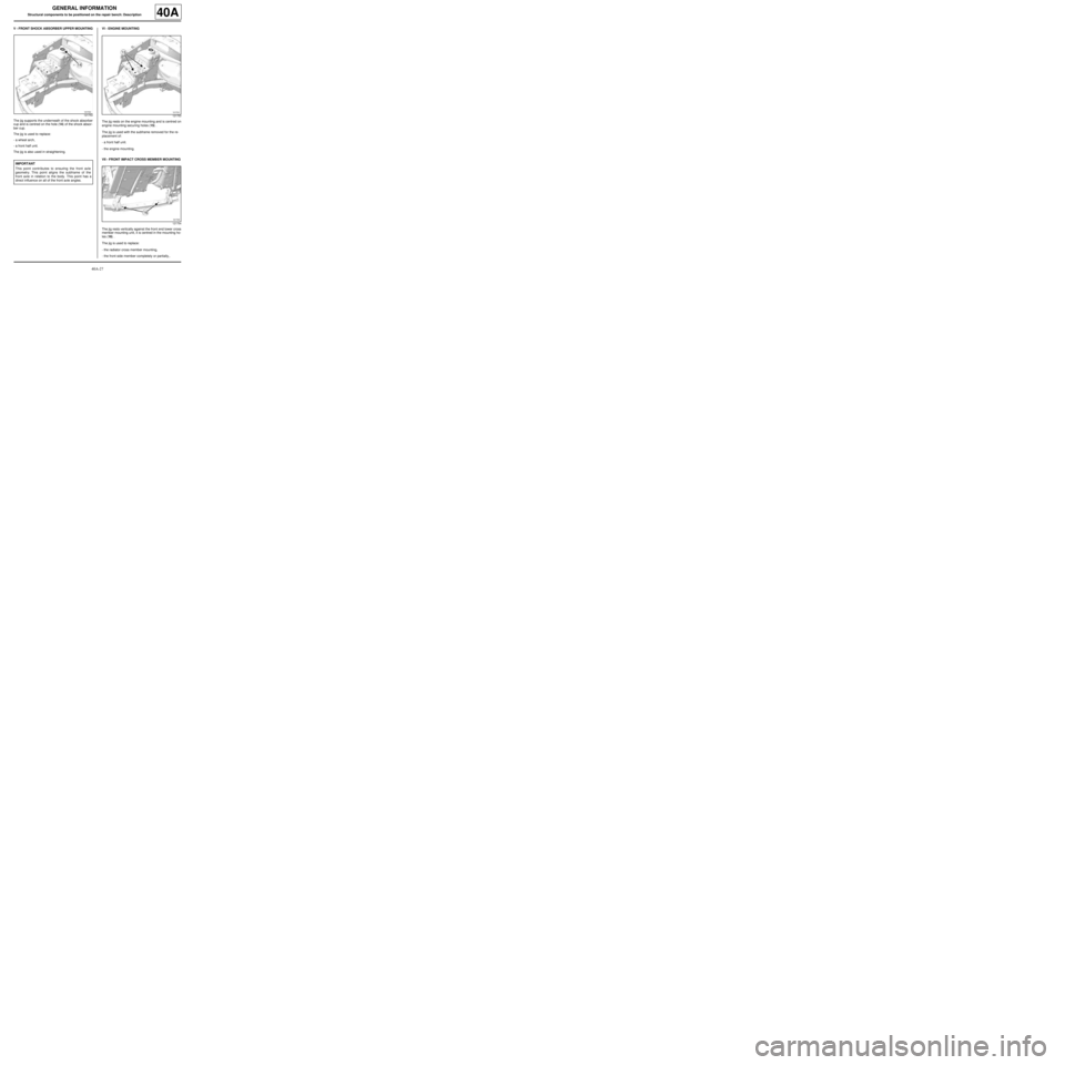
V - FRONT SHOCK ABSORBER UPPER MOUNTING
The jig supports the underneath of the shock absorber
cup and is centred on the hole (14) of the shock absor-
ber cup.
The jig is used to replace:
-a wheel arch,
-a front half unit.
The jig is also used in straightening.VI - ENGINE MOUNTING
The jig rests on the engine mounting and is centred on
engine mounting securing holes (15) .
The jig is used with the subframe removed for the re-
placement of:
-a front half unit.
-the engine mounting.
VII - FRONT IMPACT CROSS MEMBER MOUNTING
The jig rests vertically against the front end lower cross
member mounting unit, it is centred in the mounting ho-
les (16) .
The jig is used to replace:
-the radiator cross member mounting,
-the front side member completely or partially,.
121753
IMPORTANT
This point contributes to ensuring the front axle
geometry. This point aligns the subframe of the
front axle in relation to the body. This point has a
direct influence on all of the front axle angles.
121753
121754
Page 43 of 209

41A-4
FRONT LOWER STRUCTURE
Radiator mounting cross member: General description41A
DESIGN OF THE STRUCTURAL COMPONENT
This steel part, which bolts onto the end of the front
axle subframe, combines two functions:
-absorption of front impact forces,
-radiator support cross member. Note:
The information contained in the following descri-
bes the general repair procedure for all vehicles
having the same design for this part.
Before reading this general information, check that
there are no special notes associated with this vehi-
cle. These special notes will be specified if applica-
ble in other parts of this subsection dealing with the
par t.
Note:
For a detailed description of a particular connec-
tion, see MR 400.
121040
Page 44 of 209
41A-5
FRONT LOWER STRUCTURE
Radiator mounting cross member: Removal - Refitting41A
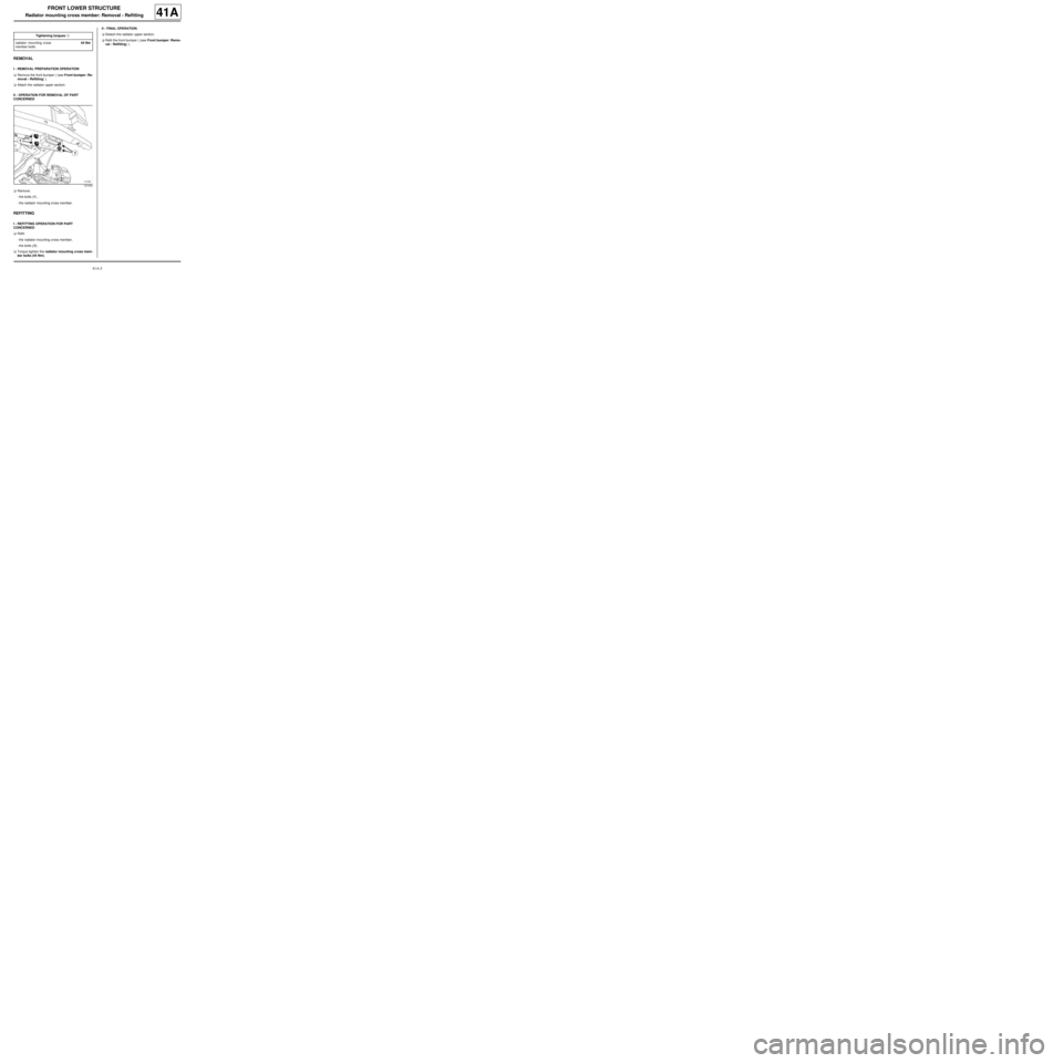
REMOVAL
I - REMOVAL PREPARATION OPERATION
aRemove the front bumper ( (see Front bumper: Re-
moval - Refitting) ).
aAttach the radiator upper section.
II - OPERATION FOR REMOVAL OF PART
CONCERNED
aRemove:
-the bolts (1) ,
-the radiator mounting cross member.
REFITTING
I - REFITTING OPERATION FOR PART
CONCERNED
aRefit:
-the radiator mounting cross member,
-the bolts (1) .
aTorque tighten the radiator mounting cross mem-
ber bolts (44 Nm).II - FINAL OPERATION.
aDetach the radiator upper section.
aRefit the front bumper ( (see Front bumper: Remo-
val - Refitting) ). Tightening torquesm
radiator mounting cross
member bolts44 Nm
121040
Page 118 of 209
42A-9
FRONT UPPER STRUCTURE
Front end panel: Removal - Refitting
42A
REMOVAL
I - REMOVAL PREPARATION OPERATION
aRemove:
-the front bumper ( (see Front bumper: Removal -
Refitting) ),
-the headlights ( (see Halogen headlight: Remo-
val - Refitting) ),
-the bonnet catch ( (see Bonnet lock: Removal -
Refitting) ).
II - OPERATION FOR REMOVAL OF PART
CONCERNED
aUnclip the wiring harness.
aRemove the bonnet opening cable.
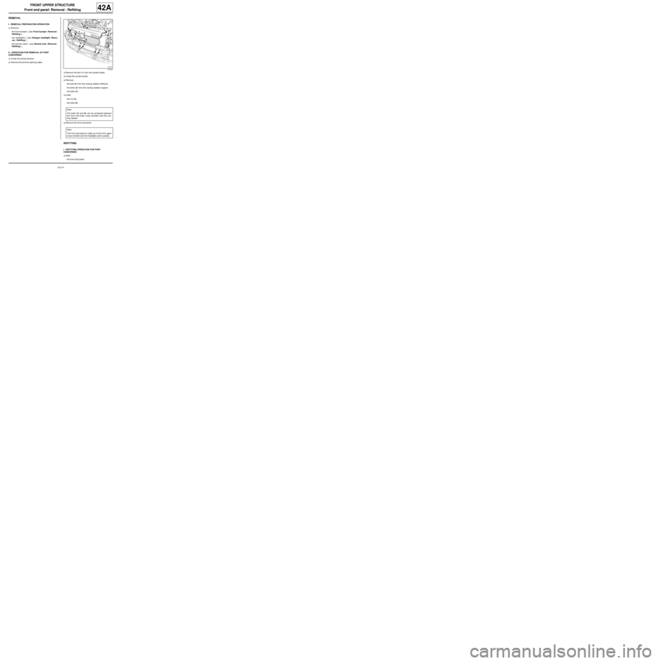
aRemove the bolt (1) from the coolant bottle.
aUnclip the coolant bottle.
aRemove:
-the bolt (2) from the cooling radiator deflector,
-the bolts (3) from the cooling radiator support,
-the bolts (4) .
aUndo:
-the nut (5) ,
-the bolts (6) .
aRemove the front end panel.
REFITTING
I - REFITTING OPERATION FOR PART
CONCERNED
aRefit:
-the front end panel,
121037
Note:
The bolts (4) and (6) can be accessed between
the front end lower cross member and the coo-
ling radiator.
Note:
The front end panel is made up of the front upper
cross member and the headlight carrier panels.
Page 119 of 209
42A-10
FRONT UPPER STRUCTURE
Front end panel: Removal - Refitting
42A
-the bolts (4) ,
-the bolts (3) on the cooling radiator support,
-the bolt (2) on the cooling radiator deflector.
aTighten:
-The bolts (6) ,
-the nut (5) .
aClip on the coolant bottle.
aRefit the bolt (1) on the coolant bottle.
aPosition the bonnet opening release cable.
aClip on the wiring harness.
II - FINAL OPERATION.
aRefit:
-the bonnet catch ( (see Bonnet lock: Removal -
Refitting) ),
-the headlights ( (see Halogen headlight: Remo-
val - Refitting) ),
-the front bumper ( (see Front bumper: Removal -
Refitting) ).
Page 122 of 209
42A-13
FRONT UPPER STRUCTURE
Front upper cross member: Removal - Refitting
42A
REMOVAL
I - REMOVAL PREPARATION OPERATION
aRemove:
-the front bumper ( (see Front bumper: Removal -
Refitting) ),
-the headlights ( (see Halogen headlight: Remo-
val - Refitting) ),
-the bonnet catch ( (see Bonnet lock: Removal -
Refitting) ).
II - OPERATION FOR REMOVAL OF PART
CONCERNED
aUnclip the wiring harness.
aRemove the bonnet opening cable.
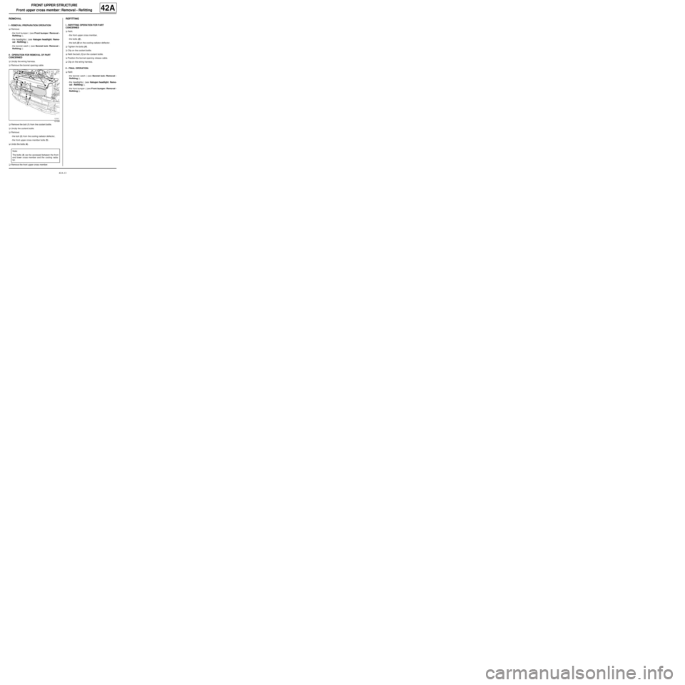
aRemove the bolt (1) from the coolant bottle.
aUnclip the coolant bottle.
aRemove:
-the bolt (2) from the cooling radiator deflector,
-the front upper cross member bolts (3) .
aUndo the bolts (4) .
aRemove the front upper cross member.
REFITTING
I - REFITTING OPERATION FOR PART
CONCERNED
aRefit:
-the front upper cross member,
-the bolts (3) ,
-the bolt (2) on the cooling radiator deflector.
aTighten the bolts (4) .
aClip on the coolant bottle.
aRefit the bolt (1) on the coolant bottle.
aPosition the bonnet opening release cable.
aClip on the wiring harness.
II - FINAL OPERATION.
aRefit:
-the bonnet catch ( (see Bonnet lock: Removal -
Refitting) ),
-the headlights ( (see Halogen headlight: Remo-
val - Refitting) ),
-the front bumper ( (see Front bumper: Removal -
Refitting) ).
121036
Note:
The bolts (4) can be accessed between the front
end lower cross member and the cooling radia-
tor.