battery RENAULT TWINGO 2009 2.G Sequential Transmission Workshop Manual
[x] Cancel search | Manufacturer: RENAULT, Model Year: 2009, Model line: TWINGO, Model: RENAULT TWINGO 2009 2.GPages: 138
Page 7 of 138

21B-7
MR-413-X44-21B000$118.mif
V2
21B
SEQUENTIAL GEARBOX
Fault finding - Fault finding log
5. FAULT FINDING LOG
You will always be asked for this log:
●when requesting technical assistance from Techline,
●for approval requests when replacing parts for which approval is mandatory,
●to be attached to monitored parts for which reimbursement is requested. The log is needed for warranty
reimbursement, and enables better analysis of the parts removed.
6. SAFETY INSTRUCTIONS
Safety rules must be observed during any work on a component to prevent any damage or injury:
Make sure the battery is properly charged to avoid damaging the computers if there is a low charge.
Use the appropriate tools. IMPORTANTIMPORTANT
Any fault on a complex system requires thorough fault finding with the appropriate tools. The
FAULT FINDING LOG, which should be completed during the procedure, enables you to keep
track of the procedure which is carried out. It is an essential document when consulting the
manufacturer.
IT IS THEREFORE MANDATORY TO FILL OUT A FAULT FINDING LOG EACH TIME FAULT FINDING
IS CARRIED OUT.
Vdiag No: 04
MR-413-X44-21B000$118.mif
Page 22 of 138

21B-22
MR-413-X44-21B000$354.mif
V2
21B
SEQUENTIAL GEARBOX
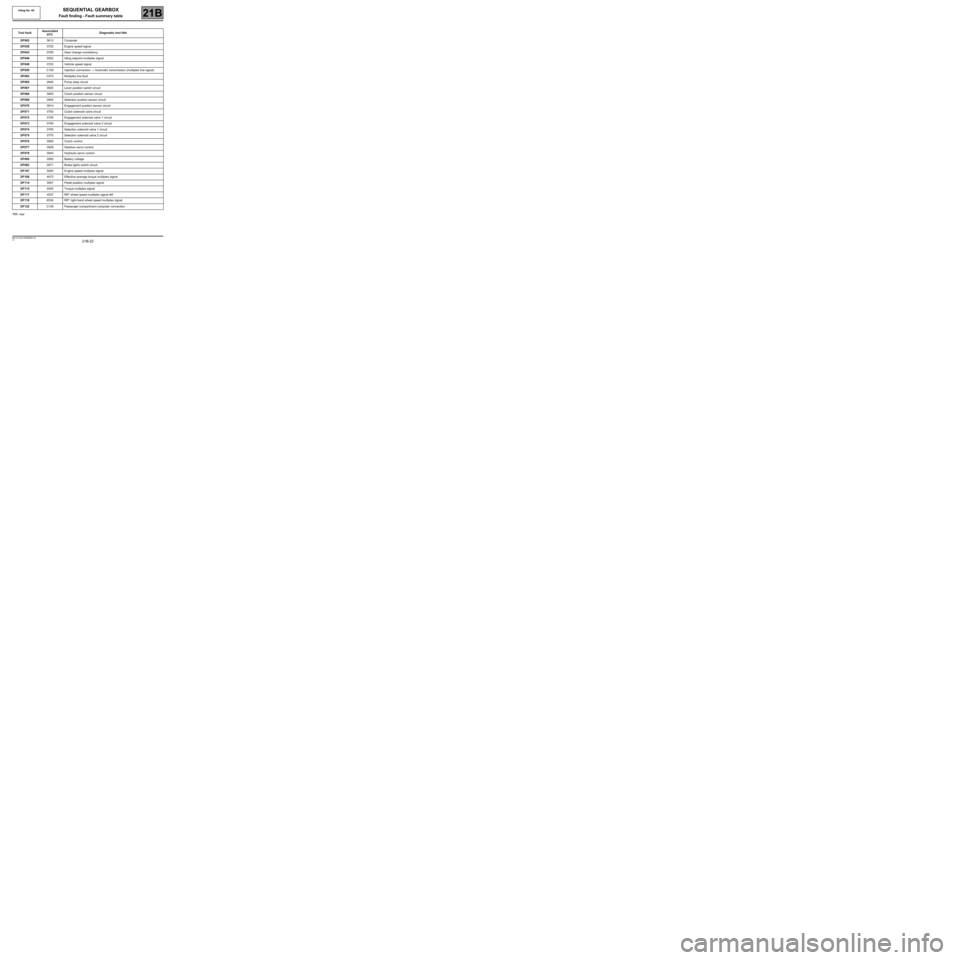
Fault finding - Fault summary table
*RR: rearTool faultAssociated
DTCDiagnostic tool title
DF0020613 Computer
DF0390725 Engine speed signal
DF0430785 Gear change consistency
DF0465002 Idling setpoint multiplex signal
DF0480720 Vehicle speed signal
DF059C100 Injection connection → Automatic transmission (multiplex line signal)
DF062C073 Multiplex line fault
DF0650945 Pump relay circuit
DF0670820 Lever position switch circuit
DF0680805 Clutch position sensor circuit
DF0690904 Selection position sensor circuit
DF0700914 Engagement position sensor circuit
DF0710750 Clutch solenoid valve circuit
DF0720755 Engagement solenoid valve 1 circuit
DF0730760 Engagement solenoid valve 2 circuit
DF0740765 Selection solenoid valve 1 circuit
DF0750770 Selection solenoid valve 2 circuit
DF0760900 Clutch control
DF0770928 Gearbox servo control
DF0780944 Hydraulic servo control
DF0800560 Battery voltage
DF0820571 Brake lights switch circuit
DF1075000 Engine speed multiplex signal
DF1084073 Effective average torque multiplex signal
DF1145007 Pedal position multiplex signal
DF1155005 Torque multiplex signal
DF1174037 RR* wheel speed multiplex signal left
DF118403A RR* right-hand wheel speed multiplex signal
DF122C140 Passenger compartment computer connection
Vdiag No: 04
MR-413-X44-21B000$354.mif
Page 45 of 138

21B-45
MR-413-X44-21B000$413.mif
V2
SEQUENTIAL GEARBOX
Fault finding - Interpretation of faults
Vdiag No.: 04
21B
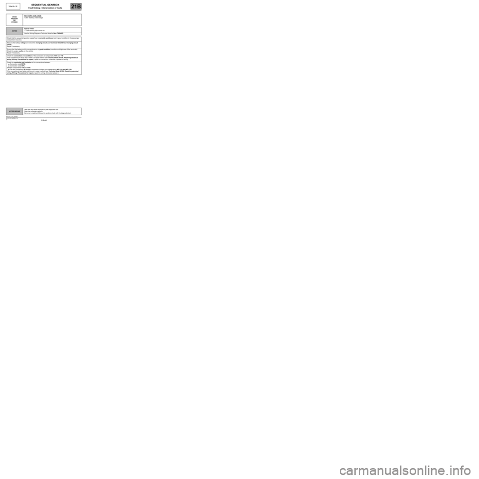
DF080
PRESENT
OR
STOREDBATTERY VOLTAGE
1.DEF: Battery undervoltage
NOTESSpecial notes:
–Fault warning light comes on.
Use the Wiring Diagrams Technical Note for New TWINGO.
Check that the sequential gearbox supply fuse is correctly positioned and in good condition in the passenger
compartment fuse box.
Measure the battery voltage and check the charging circuit (see Technical Note 6014A, Charging circuit
check).
Repair if necessary.
Ensure that the battery and its connections are in good condition (condition and tightness of the terminals).
Check the engine earths on the vehicle.
Repair if necessary.
Check the connection and condition of the connectors of components 1016 and 119.
If the connectors are faulty and if there is a repair method (see Technical Note 6015A, Repairing electrical
wiring, W iring: Precautions for repair), repair the connectors; otherwise, replace the wiring.
Check the continuity and insulation of the connections between:
●Connection code BP39,
●Connection code AP4,
between components 119 and 1016.
●The two connections N between component 119 and the chassis earths MC-12A and MC-12B.
If the connection(s) are faulty and there is a repair method (see Technical Note 6015A, Repairing electrical
wiring, W iring: Precautions for repair), repair the wiring, otherwise replace it.
AFTER REPAIRDeal with any faults displayed by the diagnostic tool.
Clear the computer memory.
Carry out a road test followed by another check with the diagnostic tool.
BVRJH1_V04_DF080
Page 107 of 138

21B -107
MR-413-X44-21B000$767.mif
V2
SEQUENTIAL GEARBOX
Fault finding - Interpretation of parameters
Vdiag No: 04
21B
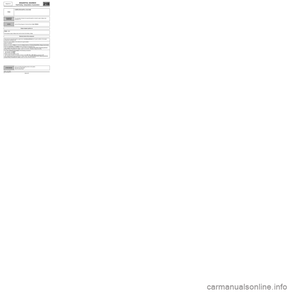
PR008
COMPUTER SUPPLY VOLTAGE
PARAMETER
DEFINITIONThis parameter indicates the sequential gearbox computer supply voltage value
expressed in V.
NOTESUse the Wiring Diagrams Technical Note for New TWINGO.
Engine stopped, ignition on
PR008 ≈ 12 V
The computer supply voltage value must be close to the battery voltage.
Electrical check of the component
Check that the sequential gearbox supply fuse is correctly positioned and in good condition in the engine
compartment connection unit.
Check the engine earths on the vehicle are in good condition.
Repair if necessary.
Measure the battery voltage and check the charge circuit (see Technical Note 6014A, Charge circuit check).
Check the connection and condition of the connections of component 119.
If the connectors are faulty and if there is a repair method (see Technical Note 6015A, Repairing electrical
wiring, W iring: Precautions for repair), repair the connectors; otherwise, replace the wiring.
Check the continuity and insulation of the following connections:
●Connection code BP39,
●Connection code AP4,
between components 1016 and 119.
●Connection code N (2 connections) between earths MC-12A and MC-12B and component 119.
If the connection(s) are faulty and there is a repair method (see Technical Note 6015A, Repairing electrical
wiring, W iring: Precautions for repair), repair the wiring, otherwise replace it.
AFTER REPAIRCarry out another fault finding check on the system.
Deal with any other faults.
Clear the stored faults.
BVRJH1_V04_PR008
Page 126 of 138

21B -126
MR-413-X44-21B000$944.mif
V2
21B
SEQUENTIAL GEARBOX
Diagnostic - Fault finding chart
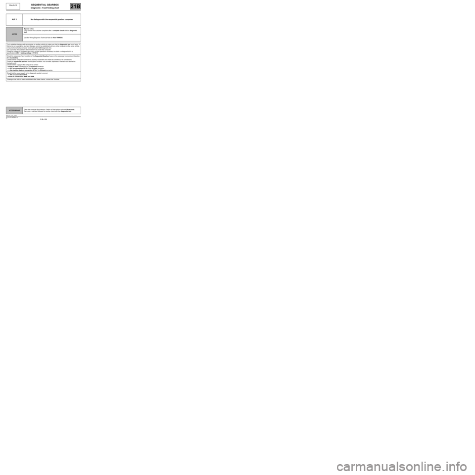
ALP 1 No dialogue with the sequential gearbox computer
NOTESSpecial notes:
Only consult this customer complaint after a complete check with the diagnostic
tool.
Use the Wiring Diagrams Technical Note for New TWINGO.
Try to establish dialogue with a computer on another vehicle to make sure that the diagnostic tool is not faulty. If
the tool is not causing the fault and dialogue cannot be established with any other computer on the same vehicle,
it may be that a faulty computer is disrupting the CAN diagnostic line.
Use a process of successive disconnections to locate this computer.
Check the voltage of the battery and carry out the operations necessary to obtain a voltage which is to
specification (9.5 V < battery voltage < 17.5 V).
Check the presence of and condition of the Sequential Gearbox fuses on the passenger compartment fuse box
(7.5 A and 20 A).
Check that the computer connector is properly connected and check the condition of its connections.
Check the sequential gearbox earths (good condition, not corroded, tightness of the earth bolt above the
hydraulic unit).
Check that the supply to the computer is correct:
–Earth on the N connections of the 52-track connector.
–+ AVC on connection BP39 of the 52-track connector.
–+ after ignition feed on connection AP4 of the 52-track connector.
Check that the power supply to the diagnostic socket is correct:
–+ AVC on connection BP19.
–Earth on connections MAM and NAM.
If dialogue has still not been established after these checks, contact the Techline.
AFTER REPAIRClear the computer fault memory. Switch off the ignition and wait 20 seconds.
Carry out a road test followed by another check with the diagnostic tool.
BVRJH1_V04_ALP1
MR-413-X44-21B000$944.mif
Vdiag No: 04