tow bar RENAULT TWINGO 2009 2.G Transmission Workshop Manual
[x] Cancel search | Manufacturer: RENAULT, Model Year: 2009, Model line: TWINGO, Model: RENAULT TWINGO 2009 2.GPages: 135
Page 9 of 135
20A-6
CLUTCH
Pressure plate - Disc: Removal - Refitting
K4M
20A
REMOVAL
I - REMOVAL PREPARATION OPERATION
aPosition the vehicle on a two-post lift (see Vehicle:
Towing and lifting) (02A, Lifting equipment).
aRemove:
-the engine undertray bolts,
-the engine undertray,
-the battery (see Battery: Removal - Refitting)
(80A, Battery)
-the air filter box (see Air filter unit: Removal - Re-
fitting) (12A, Fuel mixture),
-the petrol injection computer (see Petrol injection
computer: Removal - Refitting) (17B, Petrol in-
jection),
-the battery tray (see Battery tray: Removal - Re-
fitting) (80A, Battery),
-the front wheels (see Wheel: Removal - Refitting)
(35A, Wheels and tyres),
-the front wheel arch liners (see Front wheel arch
liner: Removal - Refitting) (55A, Exterior protec-
tion),
-the front bumper (see Front bumper: Removal -
Refitting) (55A, Exterior protection).
aDrain:
-the gearbox (see 21A, Manual gearbox, Manual
gearbox oils: Draining - Filling, page 21A-2) ,
-the engine cooling system (see Cooling system:
Draining - Refilling) (19A, Cooling),
-the refrigerant circuit (see Refrigerant circuit:
Draining - Filling) (62A, Air conditioning).aRemove:
-the rear suspended engine mounting (see Lower
engine tie-bar: Removal - Refitting) (19D, En-
gine mounting),
-the front axle subframe (see Front axle subframe:
Removal - Refitting) (31A, Front axle compo-
nents),
-the front left-hand driveshaft (see 29A, Drive-
shafts, Front left-hand driveshaft: Removal -
Refitting, page 29A-2) ,
-the front right-hand driveshaft (see 29A, Drive-
shafts, Front right-hand driveshaft: Removal -
Refitting, page 29A-8) .
-the engine - gearbox assembly (see Engine -
gearbox assembly: Removal - Refitting) (10A,
Engine and peripherals),
-the manual gearbox (see 21A, Manual gearbox,
Manual gearbox: Removal - Refitting, page 21A-
24) .
II - OPERATION FOR REMOVAL OF PART
CONCERNED
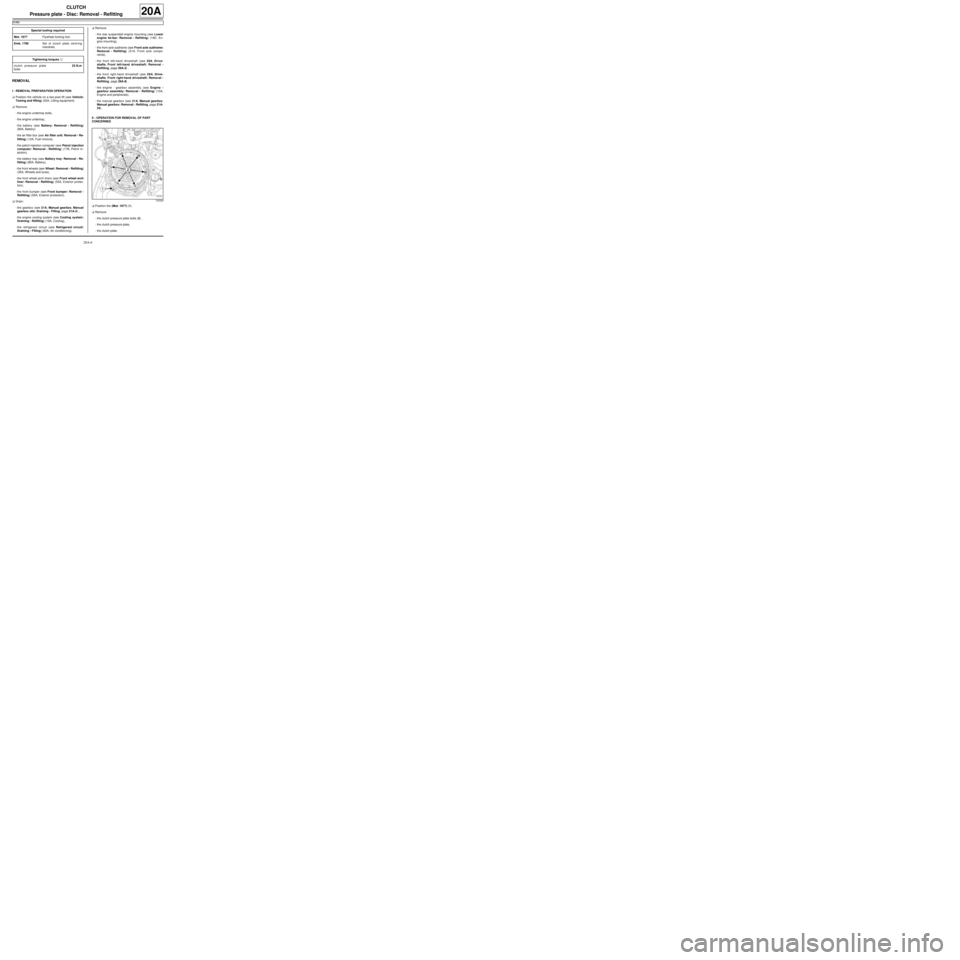
aPosition the (Mot. 1677) (1) .
aRemove:
-the clutch pressure plate bolts (2) ,
-the clutch pressure plate,
-the clutch plate. Special tooling required
Mot. 1677Flywheel locking tool.
Emb. 1780Set of clutch plate centr ing
mandrels.
Tightening torquesm
clutch pressure plate
bolts23 N.m
132329
Page 39 of 135
21A-24
MANUAL GEARBOX
Manual gearbox: Removal - Refitting
K9K, and JH3 or JR5
21A
REMOVAL
I - REMOVAL PREPARATION OPERATION
aPosition the vehicle on a two-post lift (see Vehicle:
Towing and lifting) (02A, Lifting equipment).
aRemove:
-the battery (see Battery: Removal - Refitting)
(80A, Battery),
-the battery tray (see Battery tray: Removal - Re-
fitting) (80A, Battery).
-the scuttle panel grille (see Scuttle panel grille:
Removal - Refitting) (56A, Exterior equipment),
-the scoop under the scuttle panel grille (see Scoop
under the scuttle panel grille: Removal - Refit-
ting) (56A, Exterior equipment).
aDisconnect the engine management computer con-
nectors.
aRemove:
-the engine management computer mounting bolts,
-the engine management computer mounting nuts.
aRemove the engine management computer mount-
ing.
aRemove the engine management computer wiring
harness nut from the engine management computer
mounting.
aRemove the engine management computer wiring
harness.
aRemove the engine management computer mount-
ing fitted with the engine management computer.aUnclip:
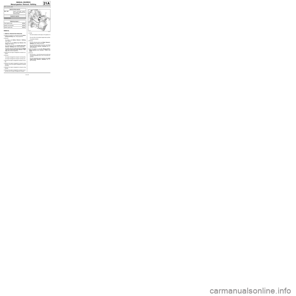
-the clutch hydraulic control pipe on the gearbox (1)
,
-the union (2) on the hydraulic tappet slave cylinder,
-the gearbox breather.
aRemove:
-the front left-hand wheel (see Wheel: Removal -
Refitting) (35A, Wheels and tyres),
-the front left-hand wheel arch liner (see Front
wheel arch liner: Removal - Refitting) (55A, Ex-
terior protection).
aDrain the gearbox oil (see 21A, Manual gearbox,
Manual gearbox oils: Draining - Filling, page
21A-2) .
aRemove:
-the hub carrier - front left-hand and front right-hand
driveshaft assemblies (see ) (31A, Front axle com-
ponents),
-the rear suspended engine mounting (see Lower
engine tie-bar: Removal - Refitting) (19D, En-
gine mounting). Special tooling required
Mot. 1453Engine anchorage support
with m ultiple adjustments and
retaining str aps.
Equipment required
component jack
Tightening torquesm
lower gearbox bolts44 N.m
gearbox nuts and bolts44 N.m
gearbox upper bolts44 N.m
121410
Page 42 of 135
21A-27
MANUAL GEARBOX
Manual gearbox: Removal - Refitting
D4F, and JB1 – D7F, and JB1
21A
REMOVAL
I - REMOVAL PREPARATION OPERATION
aPosition the vehicle on a two-post lift (see Vehicle:
Towing and lifting) (MR 411, 02A, Lifting equip-
ment).
aRemove:
-the battery (see Battery: Removal - Refitting)
(MR 411, 80A, Battery),
-the battery tray (see Battery tray: Removal - Re-
fitting) (MR 411, 80A, Battery).
aRemove the air filter unit (see Air filter unit: Re-
moval - Refitting) (MR 411, 12A, Fuel mixture).
aRemove:
-the scuttle panel grille (see Scuttle panel grille:
Removal - Refitting) (MR 412, 56A, Exterior
equipment),
-the scoop under the scuttle panel grille (see Scoop
under the scuttle panel grille: Removal - Refit-
ting) (MR 412, 56A, Exterior equipment).aDisconnect the engine management computer con-
nectors.
aRemove:
-the engine management computer mounting bolts,
-the engine management computer mounting nuts.
aRemove the engine management computer mount-
ing.
aRemove the engine management computer wiring
harness nut from the engine management computer
mounting.
aRemove the engine management computer wiring
harness.
aRemove the engine management computer mount-
ing fitted with the engine management computer.
aUnclip:
-the clutch cable,
-the gearbox breather.
aRemove:
-the left-hand front wheel (see Wheel: Removal -
Refitting) (MR 411, 35A, Wheels and tyres),
-the front left-hand wheel arch liner (see Front
wheel arch liner: Removal - Refitting) (MR 412,
55A, Exterior protection).
aDrain the gearbox oil (see 21A, Manual gearbox,
Manual gearbox oils: Draining - Filling, page
21A-2) .
aRemove:
-the hub carrier - front left-hand and front right-hand
driveshaft assemblies (see ) (MR 411, 31A, Front
axle components),
-the rear suspended engine mounting (see Lower
engine tie-bar: Removal - Refitting) (MR 411,
19D, Engine mounting),
-the starter (see Starter: Removal - Refitting) (MR
411, 16A, Starting - Charging). Special tooling required
Mot. 1453Engine anchorage support
with m ultiple adjustments and
retaining str aps.
Equipment required
component jack
Tightening torquesm
gearbox mountings44 Nm
D4F
Page 45 of 135
21A-30
MANUAL GEARBOX
Manual gearbox: Removal - Refitting
K4M, and JR5
21A
REMOVAL
I - REMOVAL PREPARATION OPERATION
aPosition the vehicle on a two-post lift (see Vehicle:
Towing and lifting) (02A, Lifting equipment).
aRemove:
-the engine undertray,
-the battery (see Battery: Removal - Refitting)
(80A, Battery),
-the air filter unit (see Air filter unit: Removal - Re-
fitting) (12A, Fuel mixture),
-the petrol injection computer (see Petrol injection
computer: Removal - Refitting) (17B, Petrol in-
jection),
-the battery tray (see Battery tray: Removal - Re-
fitting) (80A, Battery),
-the front wheels (see Wheel: Removal - Refitting)
(35A, Wheels and tyres),
-the front wheel arch liners (see Front wheel arch
liner: Removal - Refitting) (55A, Exterior protec-
tion),
-the front bumper (see Front bumper: Removal -
Refitting) (55A, Exterior protection).
aDrain:
-the gearbox (see 21A, Manual gearbox, Manual
gearbox oils: Draining - Filling, page 21A-2) ,
-the engine cooling system (see Cooling system:
Draining - Refilling) (19A, Cooling),
-the refrigerant circuit (see Refrigerant circuit:
Draining - Filling) (62A, Air conditioning).aRemove:
-the rear suspended engine mounting (see Lower
engine tie-bar: Removal - Refitting) (19D, En-
gine mounting),
-the front axle subframe (see Front axle subframe:
Removal - Refitting) (31A, Front axle compo-
nents),
-the front left-hand driveshaft (see 29A, Drive-
shafts, Front left-hand driveshaft: Removal -
Refitting, page 29A-2) ,
-the front right-hand driveshaft (see 29A, Drive-
shafts, Front right-hand driveshaft: Removal -
Refitting, page 29A-8) ,
-the differential output seals (see 21A, Manual
gearbox, Differential output seal: Removal - Re-
fitting, page 21A-38) (21A, Manual gearbox),
-the engine - gearbox assembly (see Engine -
gearbox assembly: Removal - Refitting) (10A,
Engine and peripherals).
II - OPERATION FOR REMOVAL OF PART
CONCERNED
aRemove the “engine - gearbox” assembly from
theusing a workshop hoist.
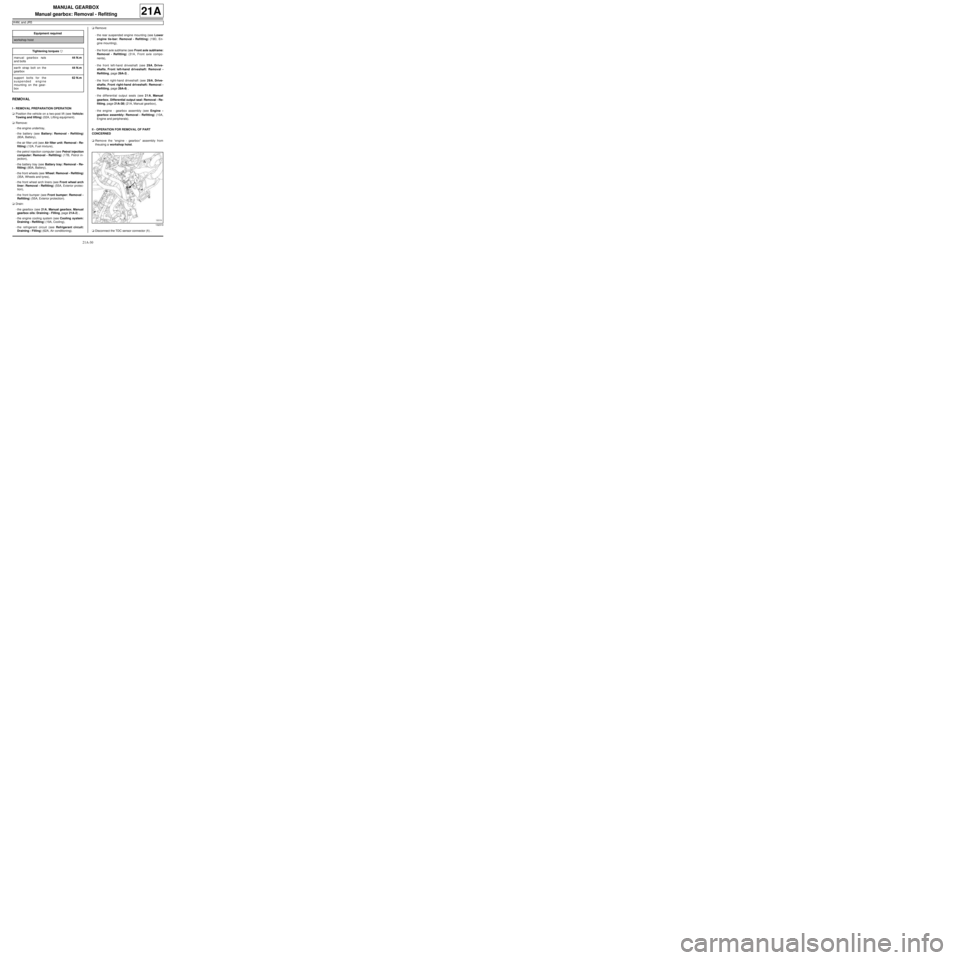
aDisconnect the TDC sensor connector (1) . Equipment required
workshop hoist
Tightening torquesm
manual gearbox nuts
and bolts44 N.m
earth strap bolt on the
gearbox44 N.m
support bolts for the
suspended engine
mounting on the gear-
box62 N.m
132319
Page 69 of 135
21B-9
SEQUENTIAL GEARBOX
Pump assembly reservoir: Removal - Refitting
D4F, and JH1
21B
The electro-hydraulic unit comprises the pump assem-
bly and the actuator module.
REMOVAL
I - REMOVAL PREPARATION OPERATION
aPosition the vehicle on a two-post lift (see Vehicle:
Towing and lifting) (MR 411, 02A, Lifting equip-
ment).
aRemove:
-the battery (see Battery: Removal - Refitting)
(MR 411, 80A, Battery),
-the sequential gearbox computer (see 21B, Se-
quential gearbox, Sequential gearbox convert-
er: Removal - Refitting, page 21B-47) ,
-the battery tray (see Battery tray: Removal - Re-
fitting) (MR 411, 80A, Battery),
-the petrol injection computer (see Petrol injection
computer: Removal - Refitting) (MR 411, 17B,
Petrol injection).
-the rear suspended engine mounting (see Lower
engine tie-bar: Removal - Refitting) (MR 411,
19D, Engine mounting),
-the left-hand front wheel (see Wheel: Removal -
Refitting) (MR 411, 35A, Wheels and tyres),-the front left-hand wheel arch liner (see Front
wheel arch liner: Removal - Refitting) (MR 412,
55A, Exterior protection),
-the electro-hydraulic unit (see 21B, Sequential
gearbox, Electro-hydraulic unit: Removal - Re-
fitting, page 21B-11) ,
aPosition the (Ms. 583)
aSeparate
-the pump assembly from the electro-hydraulic unit
(see 21B, Sequential gearbox, Pump assembly:
Removal - Refitting, page 21B-18) .
II - OPERATION FOR REMOVAL OF PART
CONCERNED
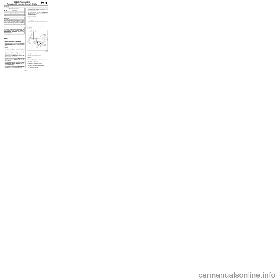
aRemove the (Ms. 583) (1) from the low pressure
hose (2) .
aDrain the pump assembly reservoir.
aRemove:
-the bolts (3) from the pump assembly reservoir,
-the electric pump unit tank.
aIn the event of replacement, remove:
-the clip (4) from the low pressure hose (2) ,
-the low pressure hose (2) . Special tooling required
Ms. 583Pipe clamps .
Equipment required
Diagnostic tool
IMPORTANT
Consult the safety and cleanliness advice and oper-
ation recommendations before carrying out any
repair (see 21B, Sequential gearbox, Sequential
gearbox: Precautions for the repair, page 21B-1)
.
Note:
To discharge the accumulator and deactivate the
pump assembly pump, (see Fault finding -
Replacement of components) (MR 413, 21B,
Sequential gearbox).
122173
Page 78 of 135
21B-18
SEQUENTIAL GEARBOX
Pump assembly: Removal - Refitting
D4F, and JH1
21B
The electro-hydraulic unit comprises the pump assem-
bly and the actuator module.
REMOVAL
I - REMOVAL PREPARATION OPERATION
aPosition the vehicle on a two-post lift (see Vehicle:
Towing and lifting) (02A, Lifting equipment).
aRemove:
-the battery (see Battery: Removal - Refitting)
(80A, Battery),
-the sequential gearbox computer (see 21B, Se-
quential gearbox, Sequential gearbox convert-
er: Removal - Refitting, page 21B-47) ,
-the battery tray (see Battery tray: Removal - Re-
fitting) (80A, Battery),-the petrol injection computer (see Petrol injection
computer: Removal - Refitting) (17B, Petrol in-
jection),
-the rear suspended engine mounting (see Lower
engine tie-bar: Removal - Refitting) (19D, En-
gine mounting),
-the front wheels (see Wheel: Removal - Refitting)
(35A, Wheels and tyres),
-the front wheel arch liners (see Front wheel arch
liner: Removal - Refitting) (55A, Exterior protec-
tion),
-the electro-hydraulic unit (see 21B, Sequential
gearbox, Electro-hydraulic unit: Removal - Re-
fitting, page 21B-11) .
II - OPERATION FOR REMOVAL OF PART
CONCERNED
aDisconnect the supply connector from the pump as-
sembly pump.
aDetach the pump assembly pump supply connector
from the electro-hydraulic unit connector mounting. Special tooling required
Ms. 583Pipe clamps .
Equipment required
Diagnostic tool
Tightening torquesm
high pressure pipe
unions14 N.m
Note:
When replacing the electric pump assembly, always
replace the control relay.
IMPORTANT
Consult the safety and cleanliness advice and oper-
ation recommendations before carrying out any
repair (see 21B, Sequential gearbox, Sequential
gearbox: Precautions for the repair, page 21B-1)
.
Note:
To discharge the accumulator and deactivate the
pump assembly pump, (see Fault finding -
Replacement of components) (21B, Sequential
gearbox).
Page 88 of 135
21B-28
SEQUENTIAL GEARBOX
Actuator module: Removal - Refitting
D4F, and JH1
21B
The electro-hydraulic unit comprises the pump assem-
bly and the actuator module.
REMOVAL
I - REMOVAL PREPARATION OPERATION
aPosition the vehicle on a two-post lift (see Vehicle:
Towing and lifting) (MR 411, 02A, Lifting equip-
ment).
aRemove:
-the battery (see Battery: Removal - Refitting)
(MR 411, 80A, Battery),
-the sequential gearbox computer (see 21B, Se-
quential gearbox, Sequential gearbox convert-
er: Removal - Refitting, page 21B-47) ,-the battery tray (see Battery tray: Removal - Re-
fitting) (MR 411, 80A, Battery),
-the petrol injection computer (see Petrol injection
computer: Removal - Refitting) (MR 411, 17B,
Petrol injection),
-the rear suspended engine mounting (see Lower
engine tie-bar: Removal - Refitting) (MR 411,
19D, Engine mounting),
-the front wheels (see Wheel: Removal - Refitting)
(MR 411, 35A, Wheels and tyres),
-the front wheel arch liners (see Front wheel arch
liner: Removal - Refitting) (MR 412, 55A, Exterior
protection),
-the electro-hydraulic unit (see 21B, Sequential
gearbox, Electro-hydraulic unit: Removal - Re-
fitting, page 21B-11) ,
-the front axle subframe (see Front axle subframe:
Removal - Refitting) (MR 411, 31A, Front axle
components).
II - OPERATION FOR REMOVAL OF PART
CONCERNED
aDisconnect the supply connector from the pump as-
sembly pump.
aDetach the pump assembly pump supply connector
from the electro-hydraulic unit connector mounting. Special tooling required
Ms. 583Pipe clamps .
Equipment required
Diagnostic tool
Tightening torquesm
high pressure pipe
unions14 N.m
IMPORTANT
Before carrying out any operation on the sequential
system, discharge the accumulator using the diag-
nostic tool.
IMPORTANT
Consult the safety and cleanliness advice and oper-
ation recommendations before carrying out any
repair (see 21B, Sequential gearbox, Sequential
gearbox: Precautions for the repair, page 21B-1)
.
Note:
To discharge the accumulator and deactivate the
pump assembly pump, (see Fault finding -
Replacement of components) (MR 413, 21B,
Sequential gearbox).
Page 98 of 135
21B-38
SEQUENTIAL GEARBOX
Sequential gearbox engine speed sensor: Removal - Refitting
D4F, and JH1
21B
REMOVAL
I - REMOVAL PREPARATION OPERATION
aPosition the vehicle on a two-post lift (see Vehicle:
Towing and lifting) (MR 411, 02A, Lifting equip-
ment).
aRemove:
-the battery (see Battery: Removal - Refitting)
(MR 411, 80A, Battery),
-the sequential gearbox computer (see 21B, Se-
quential gearbox, Sequential gearbox convert-
er: Removal - Refitting, page 21B-47) ,
-the battery tray (see Battery tray: Removal - Re-
fitting) (MR 411, 80A, Battery),
-the petrol injection computer (see Petrol injection
computer: Removal - Refitting) (MR 411, 17B,
Petrol injection),
-the rear suspended engine mounting (see Lower
engine tie-bar: Removal - Refitting) (MR 411,
19D, Engine mounting),
-the left-hand front wheel (see Wheel: Removal -
Refitting) (MR 411, 35A, Wheels and tyres),
-the front left-hand wheel arch liner (see Front
wheel arch liner: Removal - Refitting) (MR 412,
55A, Exterior protection),
-the electro-hydraulic unit (see 21B, Sequential
gearbox, Electro-hydraulic unit: Removal - Re-
fitting, page 21B-11) .aRemove:
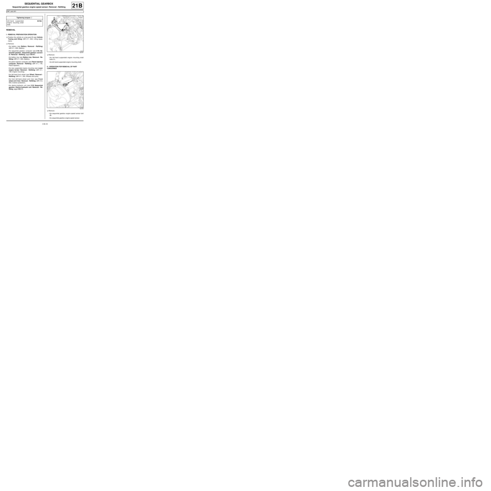
-the left-hand suspended engine mounting shaft
bolts (1) ,
-the left-hand suspended engine mounting shaft.
II - OPERATION FOR REMOVAL OF PART
CONCERNED
aRemove:
-the sequential gearbox engine speed sensor bolt
(2) ,
-the sequential gearbox engine speed sensor. Tightening torquesm
left-hand suspended
engine mounting shaft
bolts62 Nm
122161
122160