sensor RENAULT TWINGO RS 2009 2.G Chasiss ABS Owner's Manual
[x] Cancel search | Manufacturer: RENAULT, Model Year: 2009, Model line: TWINGO RS, Model: RENAULT TWINGO RS 2009 2.GPages: 76
Page 45 of 76
38C-45
MR-413-X44-38C000$517_eng.mif
V1
ANTI-LOCK BRAKING SYSTEM
Fault finding - Interpretation of faults
MK70 ABS
Vdiag No: 04
38C
DF229
PRESENT
OR
STOREDFRONT RIGHT-HAND WHEEL
1.DEF: Vehicle speed sensor signal consistent
NOTESPriorities when dealing with a number of faults:
Deal with fault DF026 Front right wheel speed sensor circuit first if it is present.
Conditions for applying the fault finding procedure to stored faults:
The fault is declared present during a road test (in excess of 12 mph (20 km/h)
for 2 minutes).
Check the condition of the axle assemblies (impacts, damage, etc.) and the conformity and good condition of the
tyres.
Check that the braking system (condition of brake pads, sealing, sticking, bleed, bearing clearance, etc.) is in
good condition.
Visually inspect the condition of the target (for clogging, metallic contamination, bearing grease, etc.) and clean
using compressed air if necessary.
If there is a lot of grease on the target, contact the Techline.
Check that the wheel speed sensor mounting is in good condition.
Check the conformity of the target (condition, number of teeth = 48) using the special command SC001 Check
target teeth.
If there is non-conformity, replace the target.
Check the connection and condition (possible damage to the wiring) of the connector of component 1094.
Check the connection and condition (possible damage to the wiring) of the connector of component 152.
If the connector is faulty (see Technical Note 6015A, Repairing electrical wiring, wiring: Precautions for
repair), repair the connector, otherwise replace the wiring.
Check for a voltage of approximately 12 V between the two connections of component 152 near
component 1094.
If a 12 V feed is not present, contact the Techline.
If all the checks are in order, swap the 2 front wheel speed sensors. Clear the computer fault memory.
Switch off the ignition. Switch the ignition back on and carry out a road test.
If a fault, which was initially registered as DF229 front right-hand wheel speed has become present DF230
front left-hand wheel speed, replace the wheel speed sensor (see MR411 Mechanical systems, 38C, Wheel
speed sensor: Removal - Refitting).
If the fault stays on the same side, the target is faulty, replace the active sensor bearing.
AFTER REPAIRClear the computer fault memory.
Carry out a road test followed by another check with the diagnostic tool.
ABS_V04_DF229
Page 46 of 76
38C-46
MR-413-X44-38C000$517_eng.mif
V1
ANTI-LOCK BRAKING SYSTEM
Fault finding - Interpretation of faults
MK70 ABS
Vdiag No: 04
38C
DF230
PRESENT
OR
STOREDFRONT LEFT-HAND WHEEL SPEED
1.DEF: Vehicle speed sensor signal consistent
NOTESPriorities when dealing with a number of faults:
Deal with fault DF006 Front left wheel speed sensor circuit first if it is present.
Conditions for applying the fault finding procedure to stored faults:
The fault is declared present during a road test (in excess of 12 mph (20 km/h)
for 2 minutes).
Check the condition of the axle assemblies (impacts, damage, etc.) and the conformity and good condition of the
tyres.
Check that the braking system (condition of brake pads, sealing, sticking, bleed, bearing clearance, etc.) is in
good condition.
Visually inspect the condition of the target (for clogging, metallic contamination, bearing grease, etc.) and clean
using compressed air if necessary.
If there is a lot of grease on the target, contact the Techline.
Check that the wheel speed sensor mounting is in good condition.
Check the conformity of the target (condition, number of teeth = 48) using the special command SC001 Check
target teeth.
If there is non-conformity, replace the target.
Check the connection and condition (possible damage to the wiring) of the connector of component 1094.
Check the connection and condition (possible damage to the wiring) of the connector of component 153.
If the connector is faulty (see Technical Note 6015A, Repairing electrical wiring, wiring: Precautions for
repair), repair the connector, otherwise replace the wiring.
Check for a voltage of approximately 12 V between the two connections of the connector of component 153 near
component 1094.
If a 12 V feed is not present, contact the Techline.
If all the checks are in order, swap the 2 front wheel speed sensors. Clear the computer fault memory.
Switch off the ignition. Switch the ignition back on and carry out a road test.
If a fault, which was initially registered as DF230 front left-hand wheel speed has become present DF229 front
right-hand wheel speed, replace the wheel speed sensor (see MR411 Mechanical systems, 38C, Wheel
speed sensor: Removal - Refitting).
If the fault stays on the same side, the target is faulty, replace the active sensor bearing.
AFTER REPAIRClear the computer fault memory.
Carry out a road test followed by another check with the diagnostic tool.
ABS_V04_DF230
Page 47 of 76
38C-47
MR-413-X44-38C000$517_eng.mif
V1
ANTI-LOCK BRAKING SYSTEM
Fault finding - Interpretation of faults
MK70 ABS
Vdiag No: 04
38C
DF231
PRESENT
OR
STOREDREAR RIGHT-HAND WHEEL
1.DEF: Vehicle speed sensor signal consistent
NOTESPriorities when dealing with a number of faults:
Deal with fault DF027 right rear wheel speed sensor circuit first if it is present.
Conditions for applying the fault finding procedure to stored faults:
The fault is declared present during a road test (in excess of 12 mph (20 km/h)
for 2 minutes).
Check the condition of the axle assemblies (impacts, damage, etc.) and the conformity and good condition of the
tyres.
Check that the braking system (condition of brake pads, sealing, sticking, bleed, bearing clearance, etc.) is in
good condition.
Visually inspect the condition of the target (for clogging, metallic contamination, bearing grease, etc.) and clean
using compressed air if necessary.
If there is a lot of grease on the target, contact the Techline.
Check that the wheel speed sensor mounting is in good condition.
Check the conformity of the target (condition, number of teeth = 48) using the special command SC001 Check
target teeth.
If there is non-conformity, replace the target.
Check the connection and condition (possible damage to the wiring) of the connector of component 1094.
Check the connection and condition (possible damage to the wiring) of the connector of component 150.
If the connector is faulty (see Technical Note 6015A, Repairing electrical wiring, wiring: Precautions for
repair), repair the connector, otherwise replace the wiring.
Check for a voltage of approximately 12 V between the two connections of component 150 near
component 1094.
If a 12 V feed is not present, contact the Techline.
If all the checks are in order, swap the 2 rear brake drums. Clear the computer fault memory.
Switch off the ignition. Switch the ignition back on and carry out a road test.
If the fault initially declared as DF231 "rear right-hand wheel speed" has become DF232 "rear left-hand wheel
speed" present, replace the complete drum (see MR411 Mechanical systems, 33A, Rear axle component).
If the fault remains on the same side, replace the speed sensor (see MR411 Mechanical systems, 38C Wheel
speed sensor, Removal - Refitting).
Important, do not forget to refit the drums to the correct wheels.
If the fault is still present, contact the Techline.
AFTER REPAIRClear the computer fault memory.
Carry out a road test followed by another check with the diagnostic tool.
ABS_V04_DF231
Page 48 of 76
38C-48
MR-413-X44-38C000$517_eng.mif
V1
ANTI-LOCK BRAKING SYSTEM
Fault finding - Interpretation of faults
MK70 ABS
Vdiag No: 04
38C
DF232
PRESENT
OR
STOREDREAR LEFT-HAND WHEEL
1.DEF: Vehicle speed sensor signal consistent
NOTESPriorities when dealing with a number of faults:
Deal with fault DF007 Rear left-hand wheel speed sensor circuit first if it is present.
Conditions for applying the fault finding procedure to stored faults:
The fault is declared present during a road test (in excess of 12 mph (20 km/h)
for 2 minutes).
Check the condition of the axle assemblies (impacts, damage, etc.) and the conformity and good condition of the
tyres.
Check that the braking system (condition of brake pads, sealing, sticking, bleed, bearing clearance, etc.) is in
good condition.
Visually inspect the condition of the target (for clogging, metallic contamination, bearing grease, etc.) and clean
using compressed air if necessary.
If there is a lot of grease on the target, contact the Techline.
Check that the wheel speed sensor mounting is in good condition.
Check the conformity of the target (condition, number of teeth = 48) using the special command SC001 Check
target teeth.
If there is non-conformity, replace the target.
Check the connection and condition (possible damage to the wiring) of the connector of component 1094.
Check the connection and condition (possible damage to the wiring) of the connector of component 151.
If the connector is faulty (see Technical Note 6015A, Repairing electrical wiring, wiring: Precautions for
repair), repair the connector, otherwise replace the wiring.
Check for a voltage of approximately 12 V between the two connections of the connector of component 151 near
component 1094.
If a 12 V feed is not present, contact the Techline.
If all the checks are in order, swap the 2 rear wheel brake drums. Clear the computer fault memory.
Switch off the ignition. Switch the ignition back on and carry out a road test.
If the fault initially declared as DF232 "rear left-hand wheel speed" has become present DF231 "rear right-
hand wheel speed", replace the complete drum. (see MR411 Mechanical systems, 33A Rear axle
components).
If the fault remains on the same side, replace the speed sensor (see MR411 Mechanical systems, 38C Wheel
speed sensor, Removal - Refitting).
Important, do not forget to refit the drums to the correct wheels.
If the fault is still present, contact the Techline.
AFTER REPAIRClear the computer fault memory.
Carry out a road test followed by another check with the diagnostic tool.
ABS_V04_DF232
Page 67 of 76
38C-67
MR-413-X44-38C000$940_eng.mif
V1
ANTI-LOCK BRAKING SYSTEM
Fault finding - Fault Finding Chart
MK70 ABS
Vdiag No: 04
38C
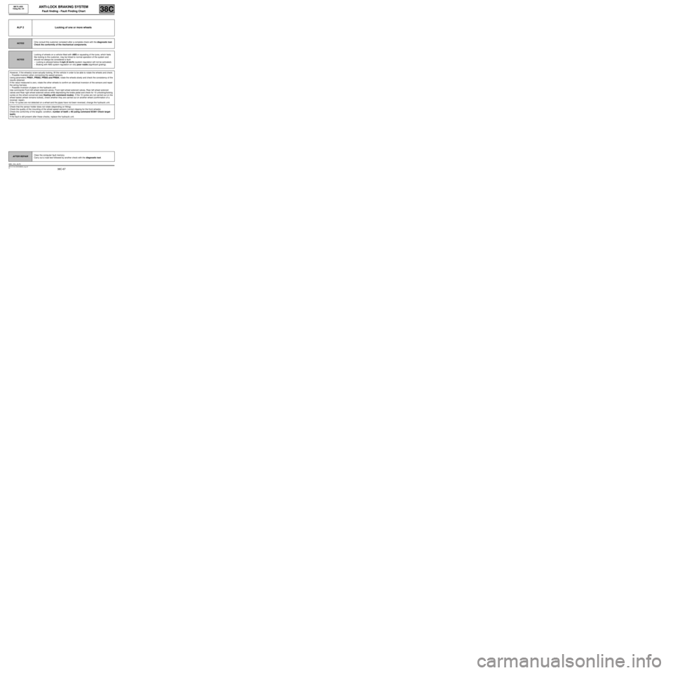
ALP 2 Locking of one or more wheels
NOTESOnly consult this customer complaint after a complete check with the diagnostic tool.
Check the conformity of the mechanical components.
NOTESLocking of wheels on a vehicle fitted with ABS or squealing of the tyres, which feels
like locking to the customer, may be linked to normal operation of the system and
should not always be considered a fault:
–Locking is allowed below 4 mph (6 km/h) (system regulation will not be activated).
–Braking with ABS system regulation on very poor roads (significant grating).
However, if the wheel(s) is/are actually locking, lift the vehicle in order to be able to rotate the wheels and check:
–Possible inversion when connecting the speed sensors.
Using parameters PR001, PR002, PR003 and PR004, rotate the wheels slowly and check the consistency of the
results obtained.
If the value measured is zero, rotate the other wheels to confirm an electrical inversion of the sensors and repair
the wiring harness.
–Possible inversion of pipes on the hydraulic unit.
Use commands Front left wheel solenoid valves, Front right wheel solenoid valves, Rear left wheel solenoid
valves and Rear right wheel solenoid valves while depressing the brake pedal and check for 10 unlocking/locking
cycles on the wheel concerned (see Dealing with command modes). If the 10 cycles are not carried out on the
wheel tested (wheel remains locked), check whether they are carried out on another wheel (confirmation of a
reversal: repair).
If the 10 cycles are not detected on a wheel and the pipes have not been reversed, change the hydraulic unit.
Check that the sensor holder does not rotate (depending on fitting).
Check the quality of the mounting of the wheel speed sensors (correct clipping for the front wheels).
Check the conformity of the targets: condition, number of teeth = 48 (using command SC001 Check target
teeth).
If the fault is still present after these checks, replace the hydraulic unit.
AFTER REPAIRClear the computer fault memory.
Carry out a road test followed by another check with the diagnostic tool.
ABS_V04_ALP2
Page 68 of 76
38C-68
MR-413-X44-38C000$940_eng.mif
V1
MK70 ABS
Vdiag No: 04ANTI-LOCK BRAKING SYSTEM
Fault finding - Fault Finding Chart38C
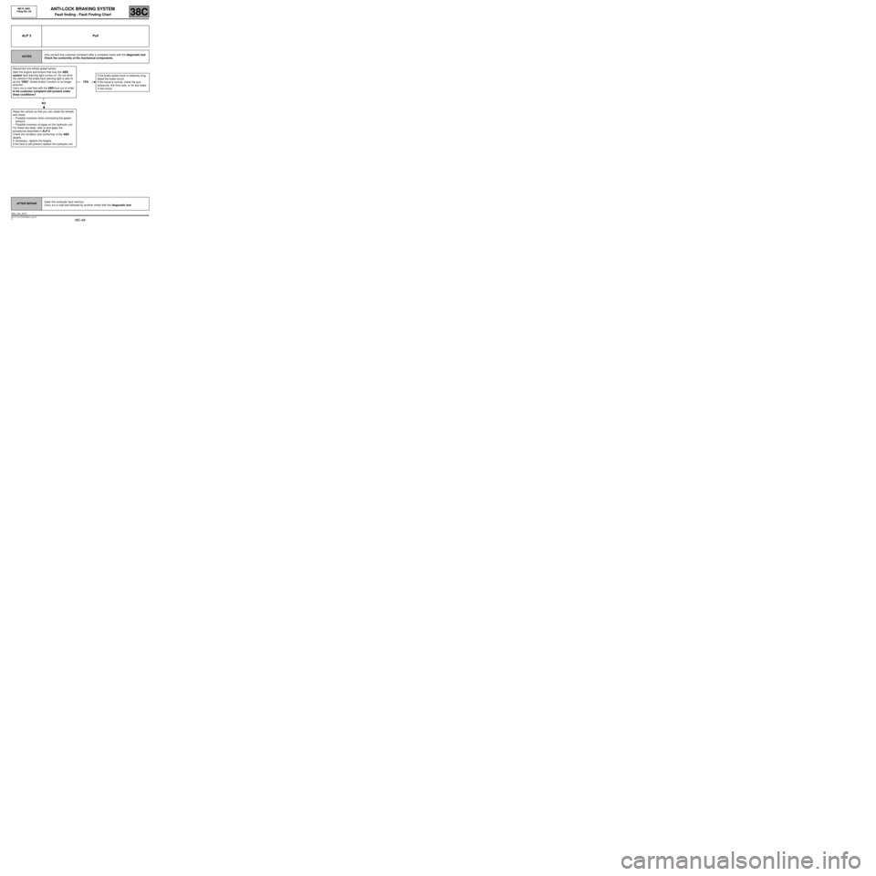
ALP 3 Pull
NOTESOnly consult this customer complaint after a complete check with the diagnostic tool.
Check the conformity of the mechanical components.
Disconnect one wheel speed sensor.
Start the engine and ensure that only the ABS
system fault warning light comes on. Do not drive
the vehicle if the brake fault warning light is also lit,
as the "EBD" (brake limiter) function is no longer
ensured.
Carry out a road test with the ABS thus out of order.
Is the customer complaint still present under
these conditions?
NO
Raise the vehicle so that you can rotate the wheels
and check:
–Possible inversion when connecting the speed
sensors.
–Possible inversion of pipes on the hydraulic unit.
For these two tests, refer to and apply the
procedures described in ALP 2.
Check the condition and conformity of the ABS
targets.
If necessary, replace the targets.
If the fault is still present replace the hydraulic unit.
YESIf the brake pedal travel is relatively long,
bleed the brake circuit.
If the travel is normal, check the tyre
pressures, the front axle, or for any leaks
in the circuit.
AFTER REPAIRClear the computer fault memory.
Carry out a road test followed by another check with the diagnostic tool.
ABS_V04_ALP3
Page 69 of 76

38C-69
MR-413-X44-38C000$940_eng.mif
V1
MK70 ABS
Vdiag No: 04ANTI-LOCK BRAKING SYSTEM
Fault finding - Fault Finding Chart38C
ALP 4 Drift
NOTESOnly consult this customer complaint after a complete check with the diagnostic tool.
Disconnect one wheel speed sensor.
Start the engine and ensure that only the ABS
system fault warning light comes on. Do not drive
the vehicle if the brake fault warning light is also lit,
as the "EBD" (brake limiter) function is no longer
ensured.
Carry out a road test with the ABS thus out of order.
Is the customer complaint still present under
these conditions?
NO
Normal behaviour linked to the system operation
during the regulation phase, mainly on surfaces with
uneven grip or which are poorly laid.
YESRoad holding fault not related to the ABS.
Check the condition of the brake linings
and that they are to specification and
check the tyre pressures, the front axle,
etc.
AFTER REPAIRClear the computer fault memory.
Carry out a road test followed by another check with the diagnostic tool.
ABS_V04_ALP4
Page 70 of 76
38C-70
MR-413-X44-38C000$940_eng.mif
V1
ANTI-LOCK BRAKING SYSTEM
Fault finding - Fault Finding Chart
MK70 ABS
Vdiag No: 04
38C
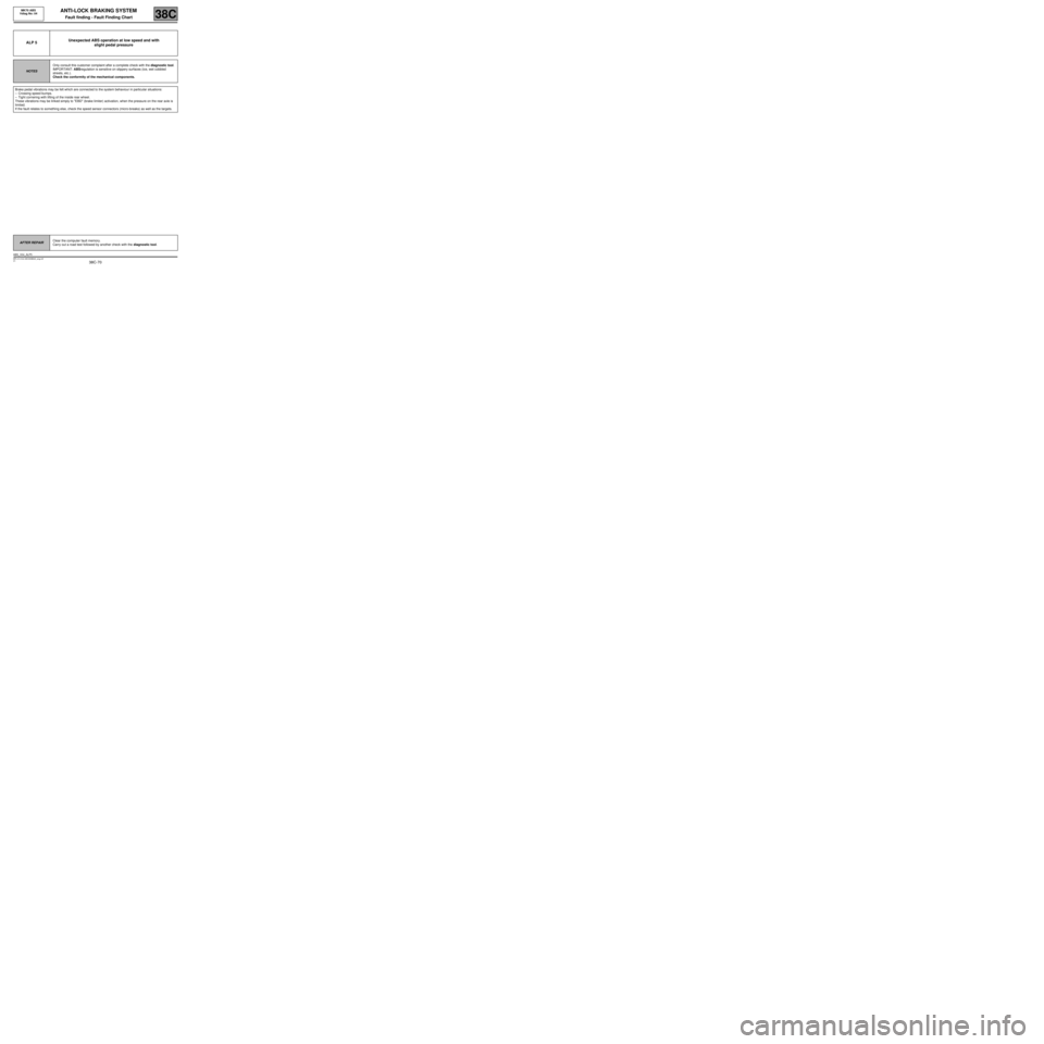
ALP 5Unexpected ABS operation at low speed and with
slight pedal pressure
NOTESOnly consult this customer complaint after a complete check with the diagnostic tool.
IMPORTANT: ABS regulation is sensitive on slippery surfaces (ice, wet cobbled
streets, etc.).
Check the conformity of the mechanical components.
Brake pedal vibrations may be felt which are connected to the system behaviour in particular situations:
–Crossing speed bumps.
–Tight cornering with lifting of the inside rear wheel.
These vibrations may be linked simply to "EBD" (brake limiter) activation, when the pressure on the rear axle is
limited.
If the fault relates to something else, check the speed sensor connectors (micro-breaks) as well as the targets.
AFTER REPAIRClear the computer fault memory.
Carry out a road test followed by another check with the diagnostic tool.
ABS_V04_ALP5