ECU RENAULT TWINGO RS 2009 2.G Electrical Equipment - Access Safety Workshop Manual
[x] Cancel search | Manufacturer: RENAULT, Model Year: 2009, Model line: TWINGO RS, Model: RENAULT TWINGO RS 2009 2.GPages: 43, PDF Size: 0.2 MB
Page 3 of 43

82D-3
MR-413-X44-82D000$100_eng.mif
V1
ACCESS/SAFETY
Fault finding - Introduction82D
Faults
Faults are declared as either present or stored (depending on whether they appeared in a certain context and have
disappeared since, or whether they remain present but have not been diagnosed within the current context).
The present or stored status of faults should be taken into consideration when the diagnostic tool is switched on
after the + after ignition feed (without any system components being active).
For a present fault, apply the procedure described in the Interpretation of faults section.
For a stored fault, note the faults displayed and apply the instructions in the Notes section.
If the fault is confirmed when the instructions in the Notes section are applied, the fault is present. Deal with the fault
If the fault is not confirmed, check:
–the electrical lines which correspond to the fault,
–the connectors on these lines (corrosion, bent pins, etc.),
–the resistance of the component detected as faulty,
–the condition of the wires (melted or split insulation, wear).
Conformity check
The aim of the conformity check is to check data that does not produce a fault on the diagnostic tool because the
data is inconsistent. Therefore, this stage is used to:
–carry out fault finding on faults that do not have a fault display, and which may correspond to a customer
complaint.
–check that the system is operating correctly and that there is no risk of a fault recurring after repairs.
This section gives the fault finding procedures for statuses and parameters and the conditions for checking them.
If a status is not behaving normally or a parameter is outside the permitted tolerance values, consult the
corresponding fault finding page.
Customer complaints - Fault finding chart
If the test with the diagnostic tool is OK but the customer complaint is still present, the fault should be processed by
customer complaints.
A summary of the overall procedure to follow is provided on the following page in the
form of a flow chart.
Page 16 of 43

82D-16
MR-413-X44-82D000$500_eng.mif
V1
ACCESS/SAFETY
Fault finding - Function82D
The ACCESS/SAFETY function is divided into three sub-functions: Access, Protection and Starting.
1. Access
a) Locking/unlocking by the user
The UCH receives the request from the user via the key.
When the key has been authenticated, the UCH executes the user's request (locking, unlocking, etc.).
Locking is indicated by 2 flashes of the direction indicators.
The direction indicators flash once when unlocking takes place (idem when unlocking the tailgate).
The maximum number of keys allocated to one vehicle is 4.
b) Electric Central Door Locking Button
This button enables the vehicle to be locked or unlocked and has no effect if the vehicle has been locked from the
outside.
Pressing the radiofrequency electric central door locking button when a door is unlocked will lock all the doors and
the electric central door locking indicator light will come on.
c) Deadlocking
To have this function, it is necessary to have a top of the range UCH on a right-hand drive vehicle, and configuration
LC003 Deadlocking must be WITH (see Configuration and programming).
This function is activated by pressing the locking button on the key and holding it down for more than 2 seconds.
This function enables the interior and exterior door opening control to be deactivated.
It is impossible to deadlock the vehicle if the + accessories feed is active, if the lights are switched on or if the hazard
warning lights are activated.
The following statuses can be viewed:
–ET044 Electric central door locking button
–ET061 Tailgate unlocking request
–ET463 "Door(s) or tailgate"
–ET061 Tailgate unlocking request
–ET186 Door locking button short press
–ET189 Door unlocking button press
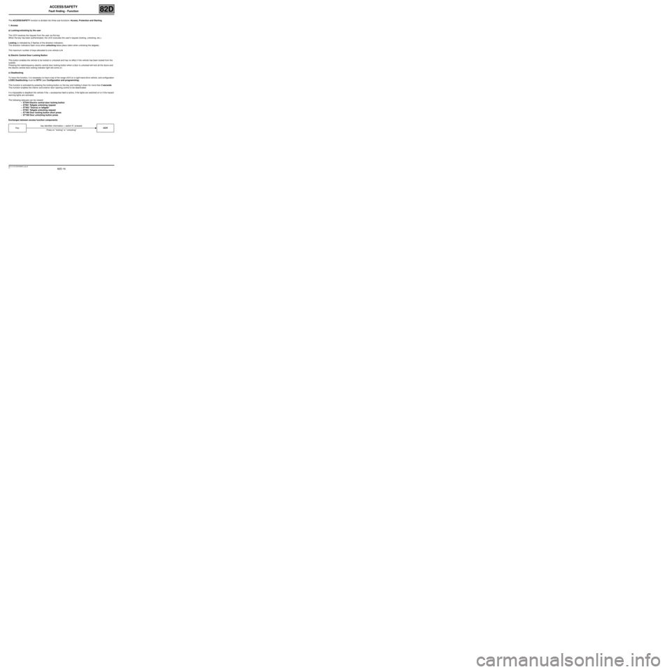
Exchanges between access function components
Keykey identifier information + switch N˚ pressed
UCH
Press on "locking" or "unlocking"
Page 41 of 43

82D-41
MR-413-X44-82D000$900_eng.mif
V1
ACCESS/SAFETY
Fault finding - Fault Finding Chart82D
ALP 25Starting protection (vehicle does not start when the ignition
key is turned)
NOTESCheck the battery voltage and the presence of (correct) fuel in the fuel tank.
Only consult this customer complaint after a complete check with the diagnostic tool.
Check the operation of the following statuses and parameters in particular: ET046
Immobiliser, ET239 Ignition switch position, ET142 Engine operation phase,
ET229 Injection immobiliser code and PR025 Engine speed.
Carry out a full conformity check on the protection and starting sub-function.
Note:
If the user makes three consecutive attempts to start the vehicle using a key which does not belong to the vehicle,
the injection computer goes into protection mode and there is no dialogue with the UCH.
Use the following procedure to bring the injection computer out of protection mode and to re-establish dialogue
between the injection computer and the UCH:
–Obtain a key which belongs to the vehicle.
–Put the key in the ignition switch in the + After ignition position for 20 seconds.
–Switch off the ignition and wait for the end of powerlatch (20 minutes).
If the engine will not start after this operation, apply the following procedure.
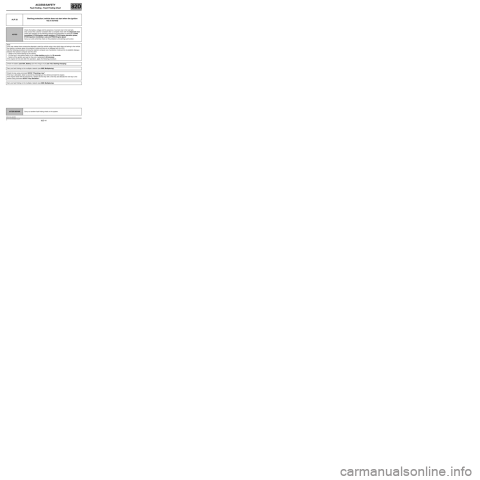
Check the battery (see 80A, Battery) and the charge circuit (see 16A, Starting-charging).
Carry out fault finding on the multiplex network (see 88B, Multiplexing).
Check the key using command SC018 "Checking a key".
If the key is allocated, obtain a second key belonging to the vehicle and start the engine.
If the engine starts with the second key, replace the first key with a new key and allocate the new key to the
vehicle using command SC015 "Key allocation".
Carry out fault finding on the multiplex network (see 88B, Multiplexing).
AFTER REPAIRCarry out another fault finding check on the system.
UCH_V44_ALP25