fuse box RENAULT TWINGO RS 2009 2.G Electrical Equipment - Access Safety Workshop Manual
[x] Cancel search | Manufacturer: RENAULT, Model Year: 2009, Model line: TWINGO RS, Model: RENAULT TWINGO RS 2009 2.GPages: 43, PDF Size: 0.2 MB
Page 7 of 43

82D-7
MR-413-X44-82D000$200_eng.mif
V1
82D
ACCESS/SAFETY
Fault finding - List and location of components
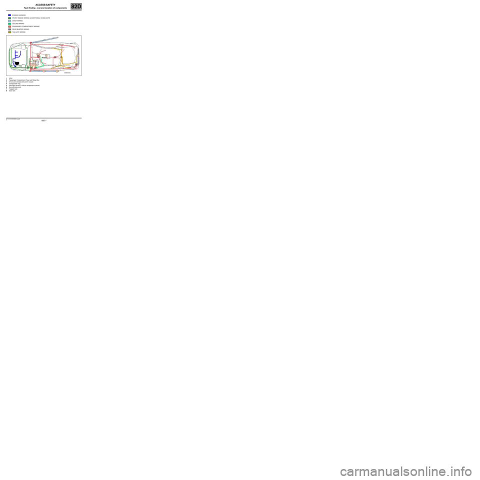
1UCH
2Passenger Compartment Fuse and Relay Box
3One touch window/anti-pinch module
4Transponder ring
5Rain/light sensor & interior temperature sensor
6Sunroof/anti-pinch
7Tailgate lock
8Door lockENGINE HARNESS
FRONT ENGINE WIRING & ADDITIONAL HEADLIGHTS
DOOR WIRING
CEILING WIRING
PASSENGER COMPARTMENT WIRING
REAR BUMPER WIRING
TAILGATE WIRING
MR-413-X44-82D000$200_eng.mif
Page 9 of 43

82D-9
MR-413-X44-82D000$400_eng.mif
V1
82D
ACCESS/SAFETY
Fault finding - Operating diagram
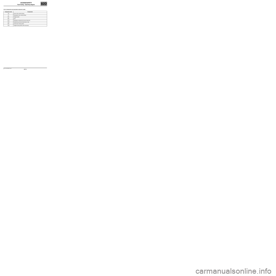
List of components and associated component codes:
Component code Components
140 Driver's door central locking
141 Passenger's door central locking
560 Tailgate switch
645 UCH
1016 Passenger compartment fuse and relay box
1042 Deadlocking activation/deactivation relay
1391 Central door locking switch
1733 Tailgate locking switch (with lock barrel)
MR-413-X44-82D000$400_eng.mif
Page 35 of 43

82D-35
MR-413-X44-82D000$900_eng.mif
V1
ACCESS/SAFETY
Fault finding - Fault Finding Chart82D
Vehicle which is not equipped with deadlocking function:
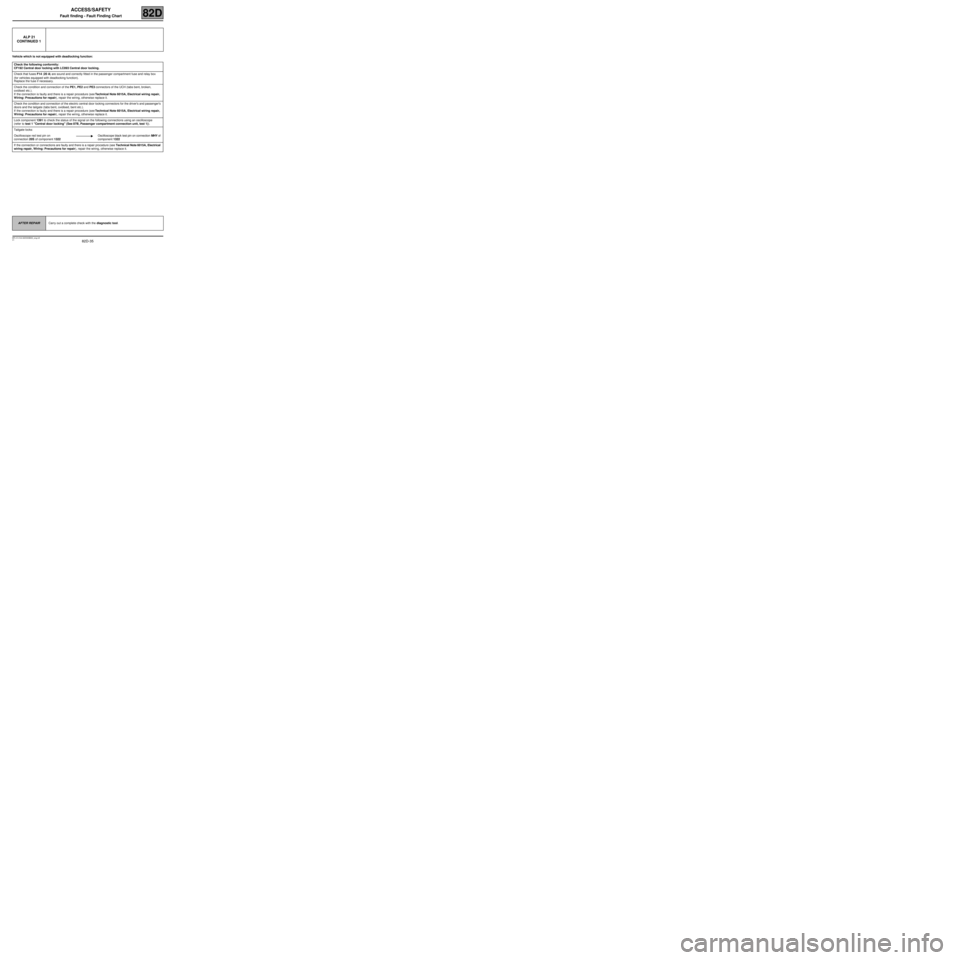
ALP 21
CONTINUED 1
Check the following conformity:
CF192 Central door locking with LC093 Central door locking.
Check that fuses F14 (20 A) are sound and correctly fitted in the passenger compartment fuse and relay box
(for vehicles equipped with deadlocking function).
Replace the fuse if necessary.
Check the condition and connection of the PE1, PE2 and PE3 connectors of the UCH (tabs bent, broken,
oxidised etc.).
If the connection is faulty and there is a repair procedure (see Technical Note 6015A, Electrical wiring repair,
Wiring: Precautions for repair), repair the wiring, otherwise replace it.
Check the condition and connection of the electric central door locking connectors for the driver's and passenger's
doors and the tailgate (tabs bent, oxidised, bent etc.).
If the connection is faulty and there is a repair procedure (see Technical Note 6015A, Electrical wiring repair,
Wiring: Precautions for repair), repair the wiring, otherwise replace it.
Lock component 1391 to check the status of the signal on the following connections using an oscilloscope
(refer to test 1 "Central door locking" (See 87B, Passenger compartment connection unit, test 1)).
Tailgate locks:
Oscilloscope red test pin on
connection 20S of component 1322Oscilloscope black test pin on connection MHY of
component 1322
If the connection or connections are faulty and there is a repair procedure (see Technical Note 6015A, Electrical
wiring repair, Wiring: Precautions for repair), repair the wiring, otherwise replace it.
AFTER REPAIRCarry out a complete check with the diagnostic tool.
Page 43 of 43

82D-43
MR-413-X44-82D000$900_eng.mif
V1
ACCESS/SAFETY
Fault finding - Fault Finding Chart82D
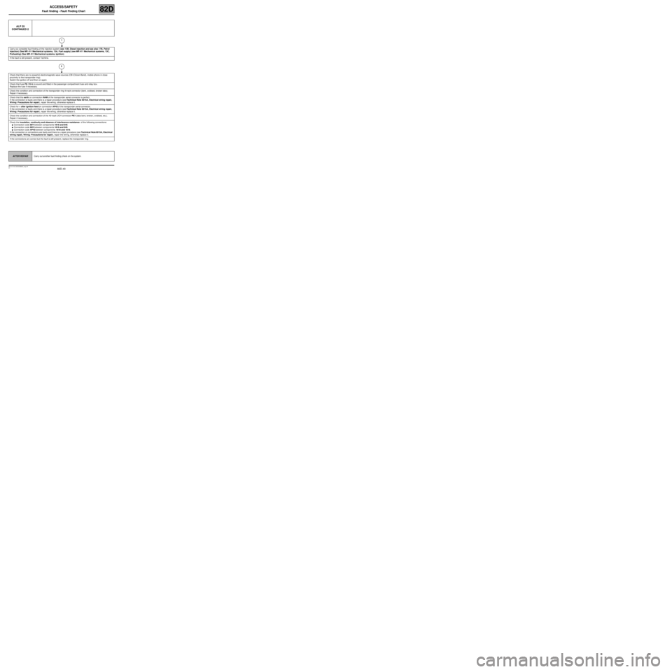
ALP 25
CONTINUED 2
Carry out complete fault finding of the injection system (see 13B, Diesel injection and see also 17B, Petrol
injection) (See MR 411 Mechanical systems, 13A, Fuel supply) (see MR 411 Mechanical systems, 13C,
Preheating) (See MR 411 Mechanical systems, Ignition).
If the fault is still present, contact Techline.
Check that there are no powerful electromagnetic wave sources (CB (Citizen Band), mobile phone in close
proximity to the transponder ring).
Switch the ignition off and then on again.
Check that fuse F8 (15 A) is sound and fitted in the passenger compartment fuse and relay box.
Replace the fuse if necessary.
Check the condition and connection of the transponder ring 4-track connector (bent, oxidised, broken tabs).
Repair if necessary.
Check that the earth on connection NAM of the transponder aerial connector is perfect.
If the connection is faulty and there is a repair procedure (see Technical Note 6015A, Electrical wiring repair,
Wiring: Precautions for repair), repair the wiring, otherwise replace it.
Check for + after ignition feed on connection AP43 of the transponder aerial connector.
If the connection is faulty and there is a repair procedure (see Technical Note 6015A, Electrical wiring repair,
Wiring: Precautions for repair), repair the wiring, otherwise replace it.
Check the condition and connection of the 40-track UCH connector PE1 (tabs bent, broken, oxidised, etc.).
Repair if necessary.
Check the insulation, continuity and absence of interference resistance of the following connections:
●Connection code 80Y between components 1618 and 645.
●Connection code 80X between components 1618 and 645.
●Connection code AP43 between components 1618 and 1016.
If the connection or connections are faulty and there is a repair procedure (see Technical Note 6015A, Electrical
wiring repair, Wiring: Precautions for repair), repair the wiring, otherwise replace it.
If the connections are correct but the fault is still present, replace the transponder ring.
AFTER REPAIRCarry out another fault finding check on the system.
1
2