check engine light RENAULT TWINGO RS 2009 2.G Electrical Equipment - Petrol Injection Workshop Manual
[x] Cancel search | Manufacturer: RENAULT, Model Year: 2009, Model line: TWINGO RS, Model: RENAULT TWINGO RS 2009 2.GPages: 348
Page 35 of 348
17B-35V7 MR-413-X44-17B000$090.mif
17B
SIM 32 Injection
Program no.: D3
Vdiag No.: 44, 4C, 50
and 54
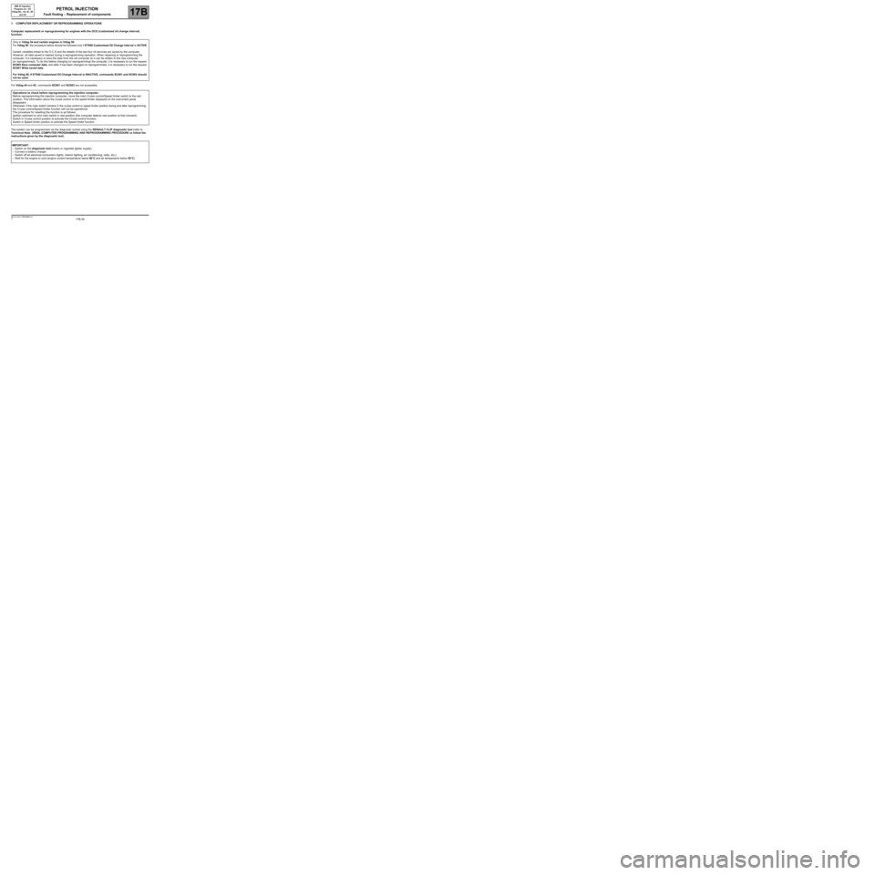
1. COMPUTER REPLACEMENT OR REPROGRAMMING OPERATIONS
Computer replacement or reprogramming for engines with the OCS (customised oil change interval)
function.
For Vdiag 44 and 4C, commands SC001 and SC003 are not accessible.
The system can be programmed via the diagnostic socket using the RENAULT CLIP diagnostic tool (refer to
Technical Note 3585A, COMPUTER PROGRAMMING AND REPROGRAMMING PROCEDURE or follow the
instructions given by the diagnostic tool). Only in Vdiag 54 and certain engines in Vdiag 50:
For Vdiag 50, the procedure below should be followed only if ET840 Customised Oil Change Interval is ACTIVE.
Certain variables linked to the O.C.S and the details of the last four oil services are saved by the computer.
However, all data saved is cleared during a reprogramming operation. When replacing or reprogramming the
computer, it is necessary to save the data from the old computer so it can be written to the new computer
(or reprogrammed). To do this before changing (or reprogramming) the computer, it is necessary to run the request
SC003 Save computer data, and after it has been changed (or reprogrammed), it is necessary to run the request
SC001 Write saved data.
For Vdiag 50, if ET840 Customised Oil Change Interval is INACTIVE, commands SC001 and SC003 should
not be used.
Operations to check before reprogramming the injection computer:
Before reprogramming the injection computer, move the main Cruise control/Speed limiter switch to the rest
position. The information about the cruise control or the speed limiter displayed on the instrument panel
disappears.
Otherwise, if the main switch remains in the cruise control or speed limiter position during and after reprogramming,
the Cruise control/Speed limiter function will not be operational.
The procedure for resetting the function is as follows:
Ignition switched on and main switch in rest position (the computer detects rest position at that moment).
Switch in Cruise control position to activate the Cruise control function.
Switch in Speed limiter position to activate the Speed limiter function.
IMPORTANT:
–Switch on the diagnostic tool (mains or cigarette lighter supply).
–Connect a battery charger.
–Switch off all electrical consumers (lights, interior lighting, air conditioning, radio, etc.).
–Wait for the engine to cool (engine coolant temperature below 60˚C and air temperature below 50˚C).
PETROL INJECTION
Fault finding – Replacement of components
Page 43 of 348
17B-43V7 MR-413-X44-17B000$131.mif
17B
SIM 32 Injection
Program no.: D3
Vdiag No.: 44, 4C, 50
and 54
* EOBD: European On Board Diagnostics
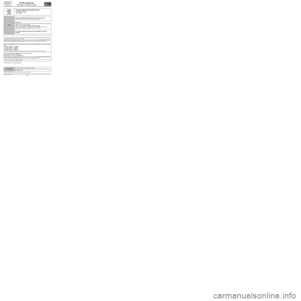
DF001
PRESENT
OR
STOREDCOOLANT TEMPERATURE SENSOR CIRCUIT
1.DEF: signal incoherence
2.DEF: abnormal voltage
3.DEF: EOBD*
NOTESConditions for applying the fault finding procedure to stored faults:
The fault is declared present when the ignition is switched on.
Special notes:
If the fault is present, the EOBD* warning light is illuminated and the low speed engine
cooling fan is permanently activated.
1.DEF: Consult the parameter PR064 Coolant temperature:
If the tool displays 120˚C, this indicates a short circuit to 12V or an open circuit.
If the tool displays - 40˚C, this indicates a short circuit to earth.
Use the Wiring Diagrams Technical Note for NEW TWINGO, E33, CLIO III,
or MODUS.
Check the condition of the connector of the coolant temperature sensor (component code 244) and of the engine
management computer (component code 120).
If the connector or connectors are faulty and if there is a repair procedure (see Technical Note 6015A, Repairing
electrical wiring, Wiring: Precautions for repair), repair the connector, otherwise replace the wiring.
Measure the resistance of the coolant temperature sensor, component code 244 between the connections 3C and
3JK:
●at 10˚C: 12030 Ω < X < 12890 Ω,
●at 25˚C: 2195 Ω < X < 2309 Ω,
●at 50˚C: 795.5 Ω < X < 826.5 Ω,
●at 80˚C: 279.3 Ω < X < 286.7 Ω.
If the coolant temperature sensor resistances are not correct, replace the coolant temperature sensor.
Check the insulation and continuity of the following connections:
●3C between components 120 and 244,
●3JK between the components 120 and 244.
If the connection or connections are faulty and there is a repair procedure (see Technical Note 6015A, Electrical
wiring repair, Wiring: Precautions for repair), repair the wiring, otherwise replace it.
If the fault is still present, contact Techline.
SIM32_V44_DF001/SIM32_V4C_DF001/SIM32_V50_DF001/SIM32_V54_DF001
PETROL INJECTION
Fault finding – Interpretation of faults
AFTER REPAIRDeal with any other faults. Clear the fault memory.
Switch off the ignition, wait 1 minute and carry out a road test followed by a check with
the diagnostic tool.
Page 44 of 348
17B-44V7 MR-413-X44-17B000$131.mif
PETROL INJECTION
Fault finding – Interpretation of faults17B
SIM 32 Injection
Program no.: D3
Vdiag No.: 44, 4C, 50
and 54
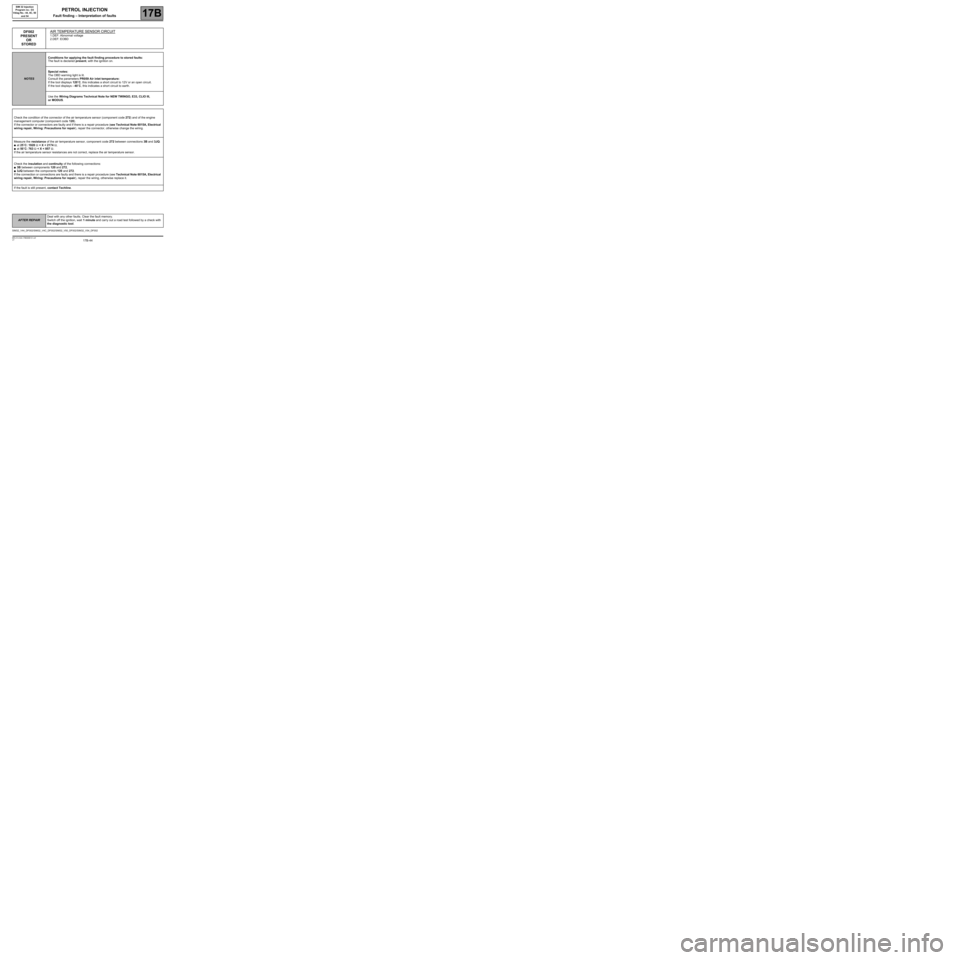
DF002
PRESENT
OR
STOREDAIR TEMPERATURE SENSOR CIRCUIT
1.DEF: Abnormal voltage
2.DEF: EOBD
NOTESConditions for applying the fault finding procedure to stored faults:
The fault is declared present, with the ignition on.
Special notes:
The OBD warning light is lit.
Consult the parameters PR059 Air inlet temperature:
If the tool displays 120˚C, this indicates a short circuit to 12V or an open circuit.
If the tool displays - 40˚C, this indicates a short circuit to earth.
Use the Wiring Diagrams Technical Note for NEW TWINGO, E33, CLIO III,
or MODUS.
Check the condition of the connector of the air temperature sensor (component code 272) and of the engine
management computer (component code 120).
If the connector or connectors are faulty and if there is a repair procedure (see Technical Note 6015A, Electrical
wiring repair, Wiring: Precautions for repair), repair the connector, otherwise change the wiring.
Measure the resistance of the air temperature sensor, component code 272 between connections 3B and 3JQ:
●at 25˚C: 1928 Ω < X < 2174 Ω,
●at 50˚C: 763 Ω < X < 857 Ω.
If the air temperature sensor resistances are not correct, replace the air temperature sensor.
Check the insulation and continuity of the following connections:
●3B between components 120 and 272,
●3JQ between the components 120 and 272.
If the connection or connections are faulty and there is a repair procedure (see Technical Note 6015A, Electrical
wiring repair, Wiring: Precautions for repair), repair the wiring, otherwise replace it.
If the fault is still present, contact Techline.
SIM32_V44_DF002/SIM32_V4C_DF002/SIM32_V50_DF002/SIM32_V54_DF002
AFTER REPAIRDeal with any other faults. Clear the fault memory.
Switch off the ignition, wait 1 minute and carry out a road test followed by a check with
the diagnostic tool.
Page 45 of 348
17B-45V7 MR-413-X44-17B000$131.mif
PETROL INJECTION
Fault finding – Interpretation of faults17B
SIM 32 Injection
Program no.: D3
Vdiag No.: 44, 4C, 50
and 54
Only Vdiag 54.
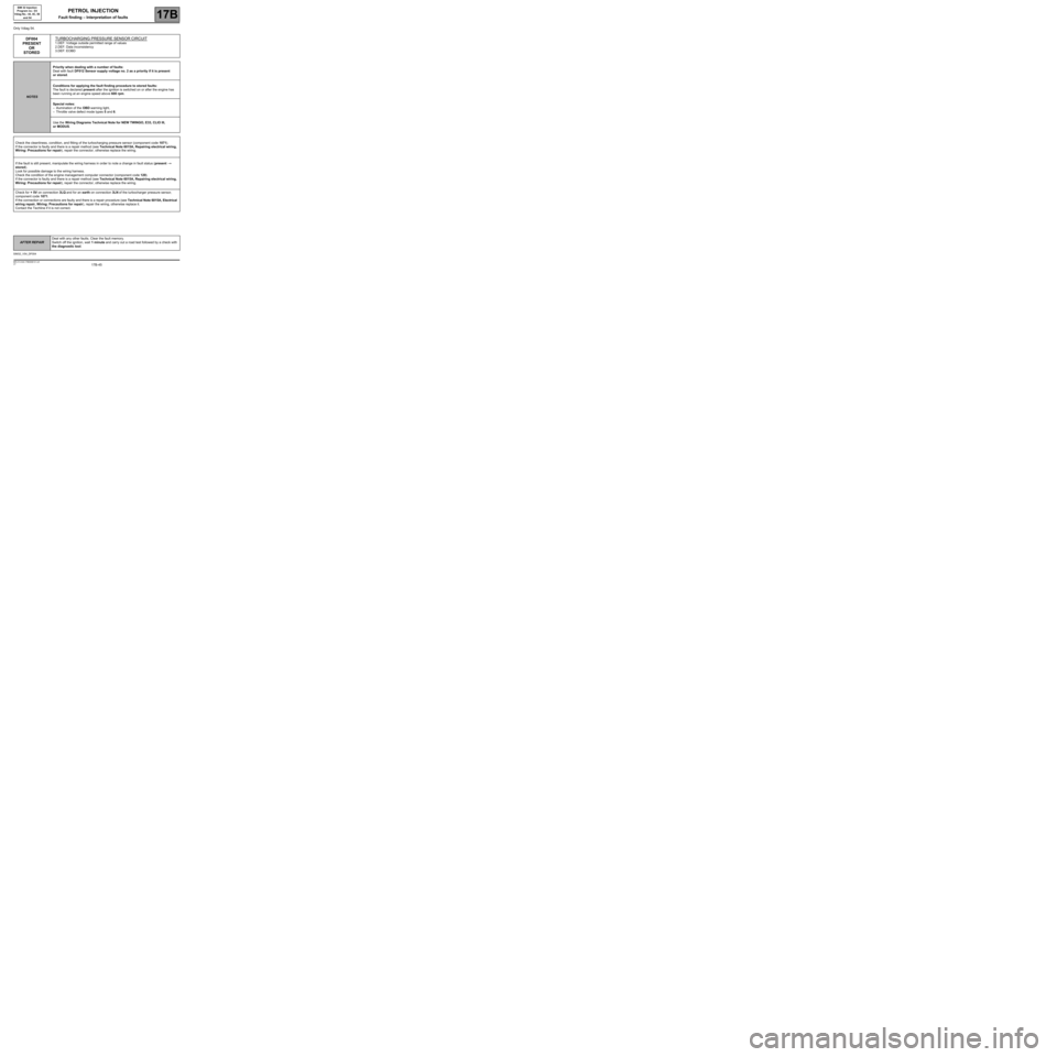
DF004
PRESENT
OR
STOREDTURBOCHARGING PRESSURE SENSOR CIRCUIT
1.DEF: Voltage outside permitted range of values
2.DEF: Data inconsistency
3.DEF: EOBD
NOTESPriority when dealing with a number of faults:
Deal with fault DF012 Sensor supply voltage no. 2 as a priority if it is present
or stored.
Conditions for applying the fault finding procedure to stored faults:
The fault is declared present after the ignition is switched on or after the engine has
been running at an engine speed above 600 rpm.
Special notes:
–illumination of the OBD warning light,
–Throttle valve defect mode types 5 and 6.
Use the Wiring Diagrams Technical Note for NEW TWINGO, E33, CLIO III,
or MODUS.
Check the cleanliness, condition, and fitting of the turbocharging pressure sensor (component code 1071).
If the connector is faulty and there is a repair method (see Technical Note 6015A, Repairing electrical wiring,
Wiring: Precautions for repair), repair the connector, otherwise replace the wiring.
If the fault is still present, manipulate the wiring harness in order to note a change in fault status (present
→
stored).
Look for possible damage to the wiring harness.
Check the condition of the engine management computer connector (component code 120).
If the connector is faulty and there is a repair method (see Technical Note 6015A, Repairing electrical wiring,
Wiring: Precautions for repair), repair the connector, otherwise replace the wiring.
Check for + 5V on connection 3LQ and for an earth on connection 3LN of the turbocharger pressure sensor,
component code 1071.
If the connection or connections are faulty and there is a repair procedure (see Technical Note 6015A, Electrical
wiring repair, Wiring: Precautions for repair), repair the wiring, otherwise replace it.
Contact the Techline if it is not correct.
SIM32_V54_DF004
AFTER REPAIRDeal with any other faults. Clear the fault memory.
Switch off the ignition, wait 1 minute and carry out a road test followed by a check with
the diagnostic tool.
Page 47 of 348

17B-47V7 MR-413-X44-17B000$131.mif
PETROL INJECTION
Fault finding – Interpretation of faults17B
SIM 32 Injection
Program no.: D3
Vdiag No.: 44, 4C, 50
and 54
DF011
PRESENT
OR
STOREDSENSOR SUPPLY VOLTAGE NO. 1
1.DEF: Abnormal voltage
2.DEF: Fault on potentiometer supply 1
3.DEF: EOBD
NOTESPriorities when dealing with a number of faults:
Deal with the fault DF084 Actuator relay control circuit or DF046 Battery voltage as
a priority if they are present or stored.
Conditions for applying the fault finding procedure to stored faults:
The fault is declared present when the ignition is switched on.
Special notes:
In the event of a short circuit to earth or to + 12V, the severity level 1 warning light is
illuminated.
The injection changes over to defect modes 4 and 5, which causes:
–the speed to be limited to 66 mph (110 km/h),
–a loss of power when accelerating (impression that the accelerator pedal is spongy),
–loss of signals from other computers and switch to safe mode on automatic and
sequential gearboxes, if required.
The OBD warning light may illuminate, depending on the sensors affected.
Use the Wiring Diagrams Technical Note for NEW TWINGO, E33, CLIO III,
or MODUS.
Check the cleanliness and condition of the sensor connections for supply voltage assembly No.1:
–manifold pressure sensor, component code 147,
–pedal potentiometer (gang 2), component code 921,
–rotary switch, component code 689,
–refrigerant fluid pressure sensor, component code 1202.
Check the condition of the engine management computer connector, component code 120.
If the connector or connectors are faulty and if there is a repair procedure (see Technical Note 6015A, Repairing
electrical wiring, Wiring: Precautions for repair), repair the connector, otherwise replace the wiring.
SIM32_V44_DF011/SIM32_V4C_DF011/SIM32_V50_DF011/SIM32_V54_DF011
AFTER REPAIRDeal with any other faults. Clear the fault memory.
Switch off the ignition, wait 1 minute and carry out a road test followed by a check with
the diagnostic tool.
Page 49 of 348
17B-49V7 MR-413-X44-17B000$131.mif
PETROL INJECTION
Fault finding – Interpretation of faults17B
SIM 32 Injection
Program no.: D3
Vdiag No.: 44, 4C, 50
and 54
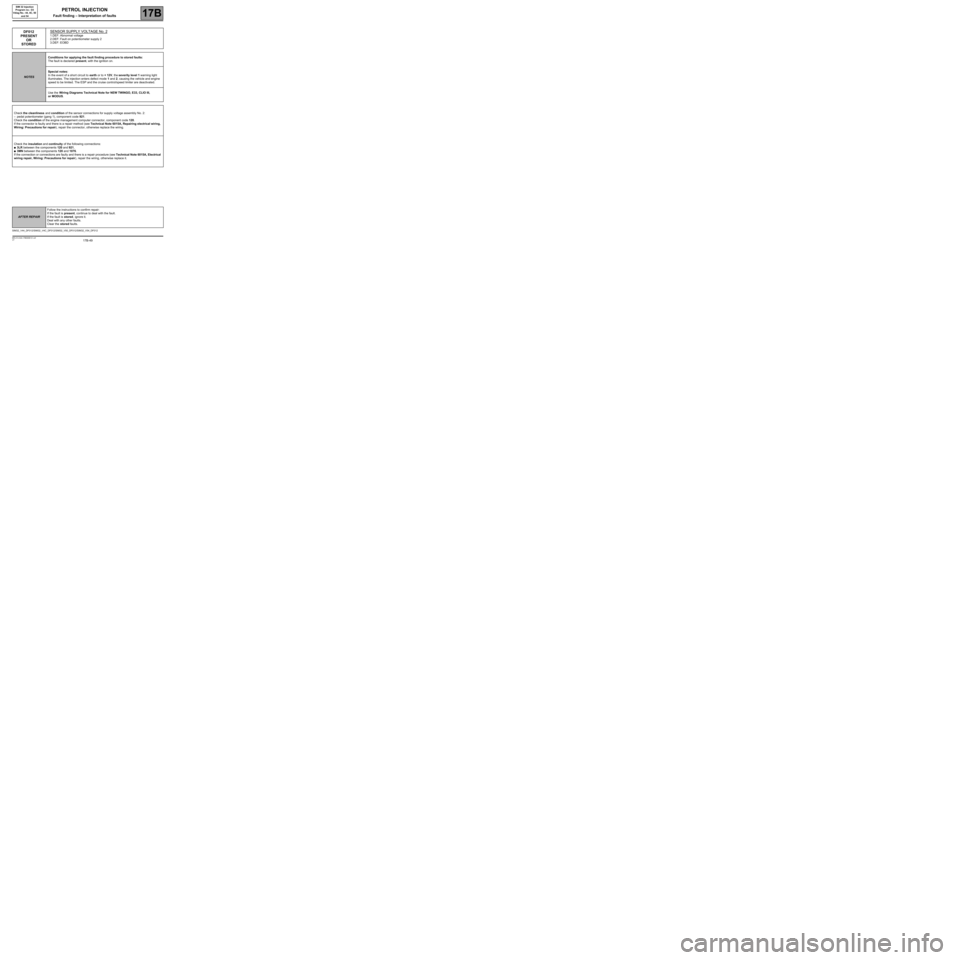
DF012
PRESENT
OR
STOREDSENSOR SUPPLY VOLTAGE No. 2
1.DEF: Abnormal voltage
2.DEF: Fault on potentiometer supply 2
3.DEF: EOBD
NOTESConditions for applying the fault finding procedure to stored faults:
The fault is declared present, with the ignition on.
Special notes:
In the event of a short circuit to earth or to + 12V, the severity level 1 warning light
illuminates. The injection enters defect mode 1 and 2, causing the vehicle and engine
speed to be limited. The ESP and the cruise control/speed limiter are deactivated.
Use the Wiring Diagrams Technical Note for NEW TWINGO, E33, CLIO III,
or MODUS.
Check the cleanliness and condition of the sensor connections for supply voltage assembly No. 2:
–pedal potentiometer (gang 1), component code 921.
Check the condition of the engine management computer connector, component code 120.
If the connector is faulty and there is a repair method (see Technical Note 6015A, Repairing electrical wiring,
Wiring: Precautions for repair), repair the connector, otherwise replace the wiring.
Check the insulation and continuity of the following connections:
●3LR between the components 120 and 921,
●3MN between the components 120 and 1076.
If the connection or connections are faulty and there is a repair procedure (see Technical Note 6015A, Electrical
wiring repair, Wiring: Precautions for repair), repair the wiring, otherwise replace it.
SIM32_V44_DF012/SIM32_V4C_DF012/SIM32_V50_DF012/SIM32_V54_DF012
AFTER REPAIRFollow the instructions to confirm repair:
If the fault is present, continue to deal with the fault.
If the fault is stored, ignore it.
Deal with any other faults.
Clear the stored faults.
Page 51 of 348
17B-51V7 MR-413-X44-17B000$131.mif
PETROL INJECTION
Fault finding – Interpretation of faults17B
SIM 32 Injection
Program no.: D3
Vdiag No.: 44, 4C, 50
and 54
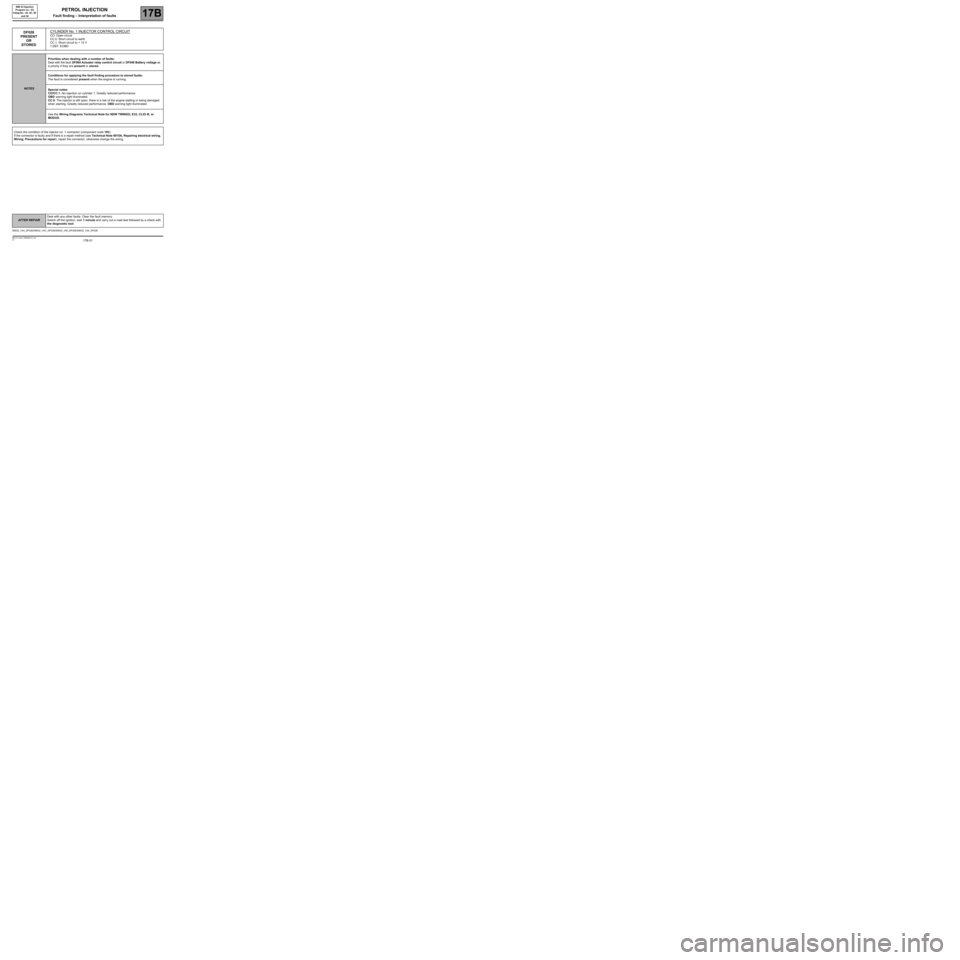
DF026
PRESENT
OR
STOREDCYLINDER No. 1 INJECTOR CONTROL CIRCUITCO: Open circuit
CC.0: Short circuit to earth
CC.1: Short circuit to + 12 V
1.DEF: EOBD
NOTESPriorities when dealing with a number of faults:
Deal with the fault DF084 Actuator relay control circuit or DF046 Battery voltage as
a priority if they are present or stored.
Conditions for applying the fault finding procedure to stored faults:
The fault is considered present when the engine is running.
Special notes:
CO/CC.1: No injection on cylinder 1. Greatly reduced performance.
OBD warning light illuminated.
CC.0: The injector is still open: there is a risk of the engine stalling or being damaged
when starting. Greatly reduced performance. OBD warning light illuminated.
Use the Wiring Diagrams Technical Note for NEW TWINGO, E33, CLIO III, or
MODUS.
Check the condition of the injector no. 1 connector (component code 193).
If the connector is faulty and if there is a repair method (see Technical Note 6015A, Repairing electrical wiring,
Wiring: Precautions for repair), repair the connector, otherwise change the wiring.
SIM32_V44_DF026/SIM32_V4C_DF026/SIM32_V50_DF026/SIM32_V54_DF026
AFTER REPAIRDeal with any other faults. Clear the fault memory.
Switch off the ignition, wait 1 minute and carry out a road test followed by a check with
the diagnostic tool.
Page 54 of 348
17B-54V7 MR-413-X44-17B000$131.mif
PETROL INJECTION
Fault finding – Interpretation of faults17B
SIM 32 Injection
Program no.: D3
Vdiag No.: 44, 4C, 50
and 54
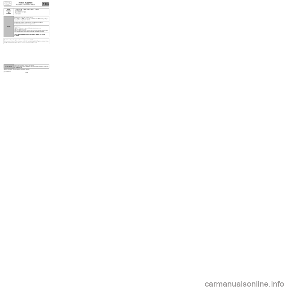
DF027
PRESENT
OR
STOREDCYLINDER No. 2 INJECTOR CONTROL CIRCUITCO: Open circuit
CC.0: Short circuit to earth
CC.1: Short circuit to + 12 V
1.DEF: EOBD
NOTESPriorities when dealing with a number of faults:
Deal with the fault DF084 Actuator relay control circuit or DF046 Battery voltage as
a priority if they are present or stored.
Conditions for applying the fault finding procedure to stored faults:
The fault is declared present with the engine running.
Special notes:
CO/CC.1: No injection on cylinder 2. Greatly reduced performance.
OBD warning light illuminated.
CC.0: The injector is still open: there is a risk of the engine stalling or being damaged
when starting. Greatly reduced performance. OBD warning light illuminated.
Use the Wiring Diagrams Technical Note for NEW TWINGO, E33, CLIO III,
or MODUS.
Check the condition of the injector no. 2 connector (component code 194).
If the connector is faulty and if there is a repair method (see Technical Note 6015A, Repairing electrical wiring,
Wiring: Precautions for repair), repair the connector, otherwise change the wiring.
SIM32_V44_DF027/SIM32_V4C_DF027/SIM32_V50_DF027/SIM32_V54_DF027
AFTER REPAIRDeal with any other faults. Clear the fault memory.
Switch off the ignition, wait 1 minute and carry out a road test followed by a check with
the diagnostic tool.
Page 58 of 348
17B-58V7 MR-413-X44-17B000$131.mif
PETROL INJECTION
Fault finding – Interpretation of faults17B
SIM 32 Injection
Program no.: D3
Vdiag No.: 44, 4C, 50
and 54
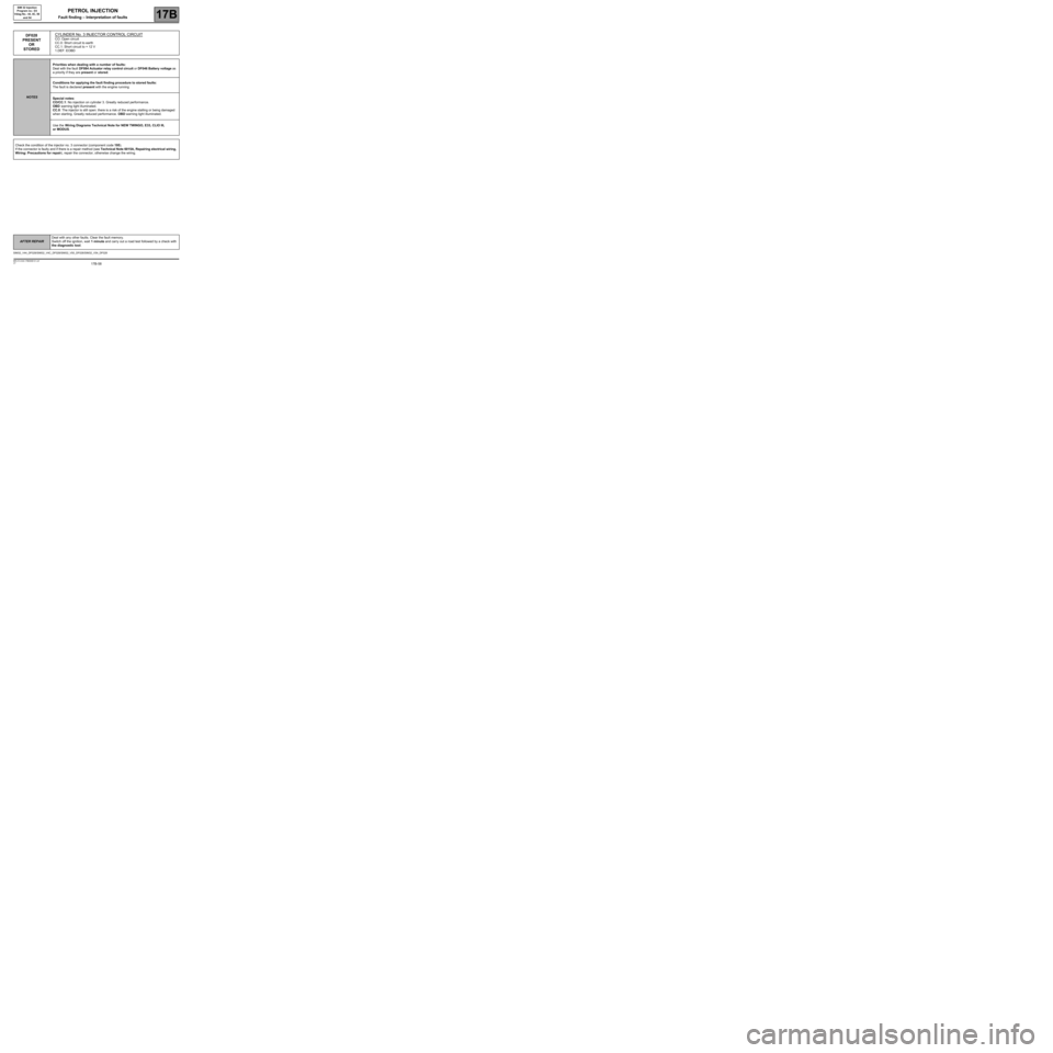
DF028
PRESENT
OR
STOREDCYLINDER No. 3 INJECTOR CONTROL CIRCUITCO: Open circuit
CC.0: Short circuit to earth
CC.1: Short circuit to + 12 V
1.DEF: EOBD
NOTESPriorities when dealing with a number of faults:
Deal with the fault DF084 Actuator relay control circuit or DF046 Battery voltage as
a priority if they are present or stored.
Conditions for applying the fault finding procedure to stored faults:
The fault is declared present with the engine running
Special notes:
CO/CC.1: No injection on cylinder 3. Greatly reduced performance.
OBD warning light illuminated.
CC.0: The injector is still open: there is a risk of the engine stalling or being damaged
when starting. Greatly reduced performance. OBD warning light illuminated.
Use the Wiring Diagrams Technical Note for NEW TWINGO, E33, CLIO III,
or MODUS.
Check the condition of the injector no. 3 connector (component code 195).
If the connector is faulty and if there is a repair method (see Technical Note 6015A, Repairing electrical wiring,
Wiring: Precautions for repair), repair the connector, otherwise change the wiring.
SIM32_V44_DF028/SIM32_V4C_DF028/SIM32_V50_DF028/SIM32_V54_DF028
AFTER REPAIRDeal with any other faults. Clear the fault memory.
Switch off the ignition, wait 1 minute and carry out a road test followed by a check with
the diagnostic tool.
Page 61 of 348
17B-61V7 MR-413-X44-17B000$131.mif
PETROL INJECTION
Fault finding – Interpretation of faults17B
SIM 32 Injection
Program no.: D3
Vdiag No.: 44, 4C, 50
and 54
DF029
PRESENT
OR
STOREDCYLINDER 4 INJECTOR CONTROL CIRCUITCO: Open circuit
CC.0: Short circuit to earth
CC.1: Short circuit to + 12 V
1.DEF: EOBD
NOTESPriorities when dealing with a number of faults:
Deal with the fault DF084 Actuator relay control circuit or DF046 Battery voltage as
a priority if they are present or stored.
Conditions for applying the fault finding procedure to stored faults:
The fault is declared present with the engine running.
Special notes:
CO/CC.1: No injection on cylinder 4. Greatly reduced performance.
OBD warning light illuminated.
CC.0: The injector is still open: there is a risk of the engine stalling or being damaged
when starting. Greatly reduced performance. OBD warning light illuminated.
Use the Wiring Diagrams Technical Note for NEW TWINGO, E33, CLIO III, or
MODUS.
Check the condition of the injector no. 4 connector (component code 196).
If the connector is faulty and if there is a repair method (see Technical Note 6015A, Repairing electrical wiring,
Wiring: Precautions for repair), repair the connector, otherwise change the wiring.
SIM32_V44_DF029/SIM32_V4C_DF029/SIM32_V50_DF029/SIM32_V54_DF029
AFTER REPAIRDeal with any other faults. Clear the fault memory.
Switch off the ignition, wait 1 minute and carry out a road test followed by a check with
the diagnostic tool.