check engine RENAULT TWINGO RS 2009 2.G Electrical Equipment - Petrol Injection Owners Manual
[x] Cancel search | Manufacturer: RENAULT, Model Year: 2009, Model line: TWINGO RS, Model: RENAULT TWINGO RS 2009 2.GPages: 348
Page 165 of 348
17B-165V7 MR-413-X44-17B000$133.mif
PETROL INJECTION
Fault finding – Interpretation of faults17B
SIM 32 Injection
Program no.: D3
Vdiag No.: 44, 4C, 50
and 54
For Clio III and Modus:
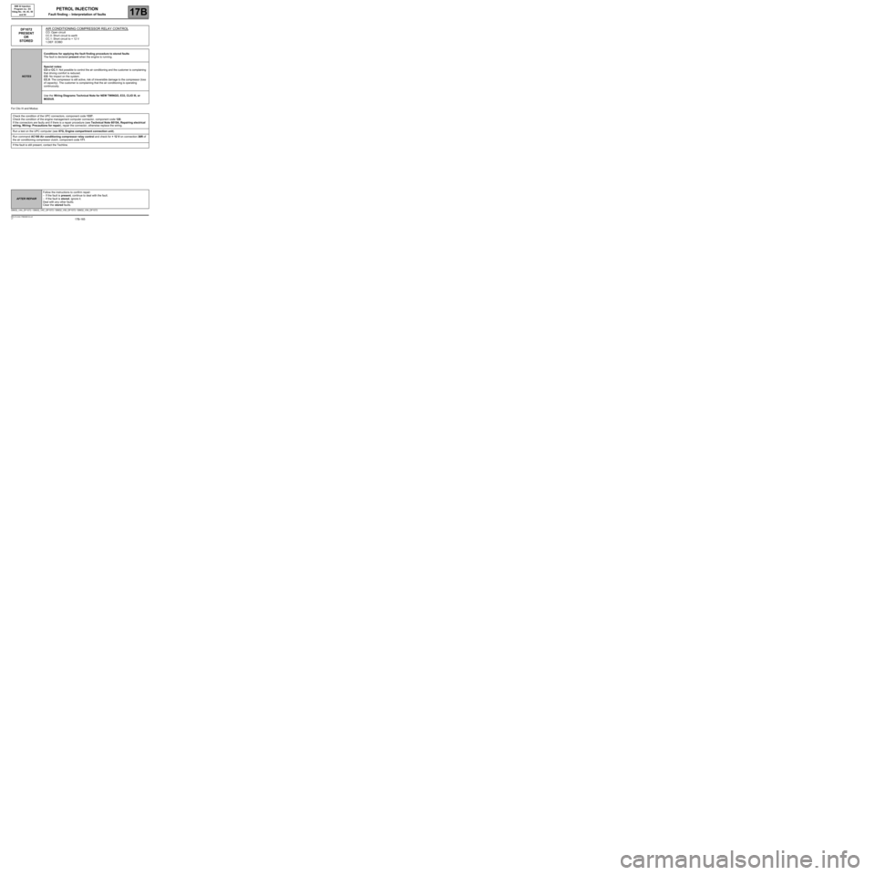
DF1072
PRESENT
OR
STOREDAIR CONDITIONING COMPRESSOR RELAY CONTROLCO: Open circuit
CC.0: Short circuit to earth
CC.1: Short circuit to + 12 V
1.DEF: EOBD
NOTESConditions for applying the fault finding procedure to stored faults
The fault is declared present when the engine is running.
Special notes:
CO or CC.1: Not possible to control the air conditioning and the customer is complaining
that driving comfort is reduced.
CO: No impact on the system.
CC.0: The compressor is still active, risk of irreversible damage to the compressor (loss
of capacity). The customer is complaining that the air conditioning is operating
continuously.
Use the Wiring Diagrams Technical Note for NEW TWINGO, E33, CLIO III, or
MODUS.
Check the condition of the UPC connectors, component code 1337.
Check the condition of the engine management computer connector, component code 120.
If the connectors are faulty and if there is a repair procedure (see Technical Note 6015A, Repairing electrical
wiring, Wiring: Precautions for repair), repair the connector, otherwise replace the wiring.
Run a test on the UPC computer (see 87G, Engine compartment connection unit).
Run command AC180 Air conditioning compressor relay control and check for + 12 V on connection 38R of
the air conditioning compressor clutch, component code 171.
If the fault is still present, contact the Techline.
SIM32_V44_DF1072 / SIM32_V4C_DF1072 / SIM32_V50_DF1072 / SIM32_V54_DF1072
AFTER REPAIRFollow the instructions to confirm repair:
–If the fault is present, continue to deal with the fault.
–If the fault is stored, ignore it.
Deal with any other faults.
Clear the stored faults.
Page 166 of 348
17B-166V7 MR-413-X44-17B000$133.mif
PETROL INJECTION
Fault finding – Interpretation of faults17B
SIM 32 Injection
Program no.: D3
Vdiag No.: 44, 4C, 50
and 54
For New Twingo and E33
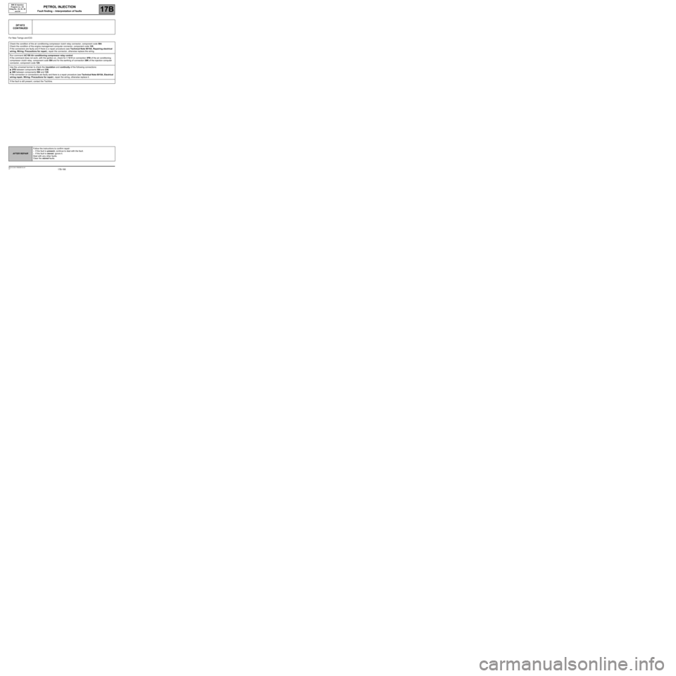
DF1072
CONTINUED
Check the condition of the air conditioning compressor clutch relay connector, component code 584.
Check the condition of the engine management computer connector, component code 120.
If the connectors are faulty and if there is a repair procedure (see Technical Note 6015A, Repairing electrical
wiring, Wiring: Precautions for repair), repair the connector, otherwise replace the wiring.
Run command AC180 Air conditioning compressor relay control
If the command does not work, with the ignition on, check for + 12 V on connection 3FB of the air conditioning
compressor clutch relay, component code 584 and for the earthing of connection 38K of the injection computer
connector, component code 120.
Use the universal bornier to check the insulation and continuity of the following connections:
●3FB between components 584 and 238,
●38K between components 584 and 120.
If the connection or connections are faulty and there is a repair procedure (see Technical Note 6015A, Electrical
wiring repair, Wiring: Precautions for repair), repair the wiring, otherwise replace it.
If the fault is still present, contact the Techline.
AFTER REPAIRFollow the instructions to confirm repair:
–If the fault is present, continue to deal with the fault.
–If the fault is stored, ignore it.
Deal with any other faults.
Clear the stored faults.
Page 171 of 348
17B-171V7 MR-413-X44-17B000$151.mif
17B
SIM 32 Injection
Program no.: D3
Vdiag No.: 44, 4C, 50
and 54
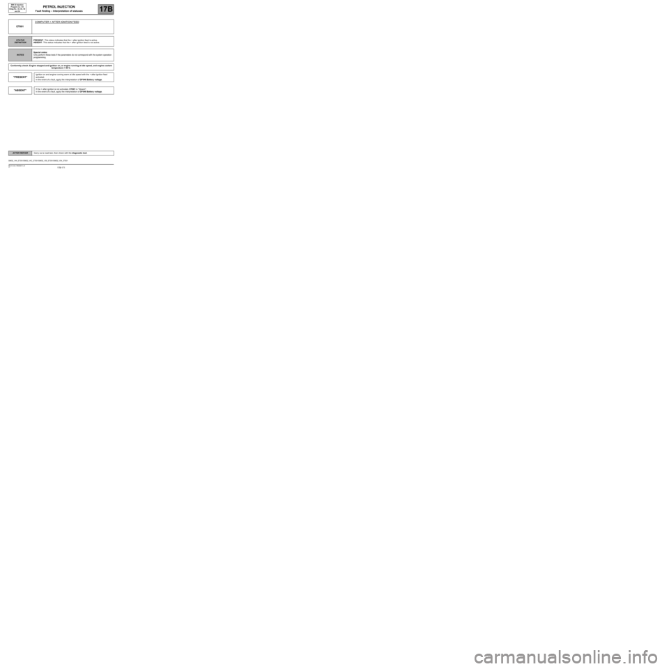
ET001COMPUTER + AFTER IGNITION FEED
STATUS
DEFINITIONPRESENT: This status indicates that the + after ignition feed is active.
ABSENT: This status indicates that the + after ignition feed is not active.
NOTESSpecial notes:
Only perform these tests if the parameters do not correspond with the system operation
programming.
Conformity check: Engine stopped and ignition on, or engine running at idle speed, and engine coolant
temperature > 80˚C.
"PRESENT"
Ignition on and engine running warm at idle speed with the + after ignition feed
activated.
In the event of a fault, apply the interpretation of DF046 Battery voltage.
"ABSENT"If the + after ignition is not activated, ET001 is "Absent".
In the event of a fault, apply the interpretation of DF046 Battery voltage.
SIM32_V44_ET001/SIM32_V4C_ET001/SIM32_V50_ET001/SIM32_V54_ET001
AFTER REPAIRCarry out a road test, then check with the diagnostic tool.
PETROL INJECTION
Fault finding – Interpretation of statuses
Page 172 of 348

17B-172V7 MR-413-X44-17B000$151.mif
PETROL INJECTION
Fault finding – Interpretation of statuses17B
SIM 32 Injection
Program no.: D3
Vdiag No.: 44, 4C, 50
and 54
ET003ENGINE IMMOBILISER
STATUS
DEFINITIONACTIVE: This status indicates that the immobiliser is active.
INACTIVE: This status indicates that the immobiliser is inactive.
NOTESSpecial notes:
Only perform these tests if the parameters do not correspond with the system operation
programming.
Conformity check: Engine stopped and ignition on, or engine running at idle speed, and engine coolant
temperature > 80˚C.
"ACTIVE"Refer to the fault finding note for the UCH (see 87B, Passenger compartment
connection unit).
"INACTIVE"Refer to the fault finding note for the UCH (see 87B, Passenger compartment
connection unit).
SIM32_V44_ET003/SIM32_V4C_ET003/SIM32_V50_ET003/SIM32_V54_ET003
AFTER REPAIRCarry out a road test, then check with the diagnostic tool.
Page 173 of 348
17B-173V7 MR-413-X44-17B000$151.mif
PETROL INJECTION
Fault finding – Interpretation of statuses17B
SIM 32 Injection
Program no.: D3
Vdiag No.: 44, 4C, 50
and 54
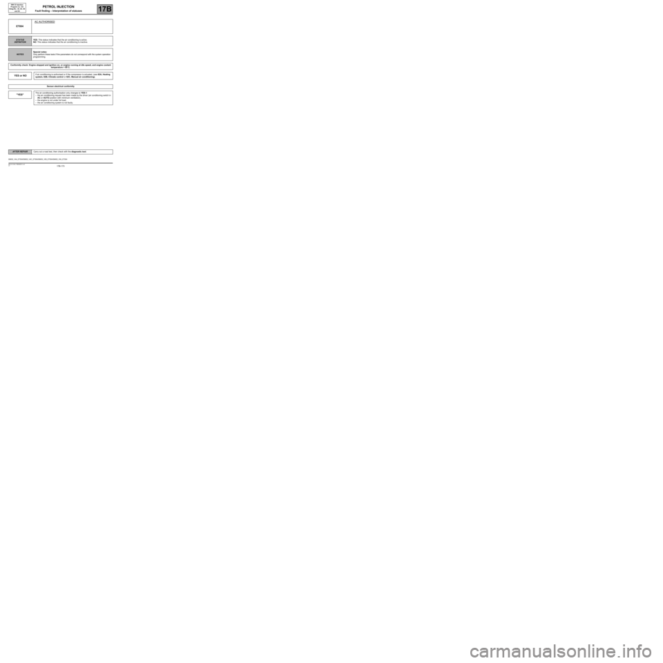
ET004AC AUTHORISED
STATUS
DEFINITIONYES: This status indicates that the air conditioning is active.
NO: This status indicates that the air conditioning is inactive.
NOTESSpecial notes:
Only perform these tests if the parameters do not correspond with the system operation
programming.
Conformity check: Engine stopped and ignition on, or engine running at idle speed, and engine coolant
temperature > 80˚C.
YES or NOIf air conditioning is authorised or if the compressor is actuated, (see 62A, Heating
system, 62B, Climate control or 62C, Manual air conditioning).
Sensor electrical conformity
"YES"The air conditioning authorisation only changes to YES if:
–the air conditioning request has been made by the driver (air conditioning switch in
AC or AUTO position with minimum ventilation),
–the engine is not under full load,
–the air conditioning system is not faulty.
SIM32_V44_ET004/SIM32_V4C_ET004/SIM32_V50_ET004/SIM32_V54_ET004
AFTER REPAIRCarry out a road test, then check with the diagnostic tool.
Page 174 of 348
17B-174V7 MR-413-X44-17B000$151.mif
PETROL INJECTION
Fault finding – Interpretation of statuses17B
SIM 32 Injection
Program no.: D3
Vdiag No.: 44, 4C, 50
and 54
ET004
CONTINUED
"NO"
Status ET004 remains at NO under the following conditions:
–Vehicle stopped with the ignition on,
–faults present in the air conditioning circuit,
–no air conditioning request made by the driver,
–engine under full load.
If status ET004 remains NO then the air conditioning should be authorised, check:
–that the air conditioning compressor is activated correctly,
–the air conditioning system feed fuses,
–the presence of refrigerant in the air conditioning circuit,
If the fault is still present, check the air conditioning computer faults
(see 62A, Heating, 62B, Climate control or 62C, Manual air conditioning).
AFTER REPAIRCarry out a road test, then check with the diagnostic tool.
Page 175 of 348
17B-175V7 MR-413-X44-17B000$151.mif
PETROL INJECTION
Fault finding – Interpretation of statuses17B
SIM 32 Injection
Program no.: D3
Vdiag No.: 44, 4C, 50
and 54
ET021HIGH-SPEED FAN REQUEST–Active
–Inactive
STATUS
DEFINITIONACTIVE: This status indicates that the high-speed fan assembly is active.
INACTIVE: This status indicates that the high-speed fan assembly is inactive.
NOTESSpecial notes:
Apply the checks only if statuses ACTIVE and INACTIVE are inconsistent.
Refer to the Wiring Diagrams Technical Note for NEW TWINGO, E33, CLIO III
or MODUS.
Conformity check: Engine stopped and ignition on, or engine running at idle speed, and engine coolant
temperature > 80˚C.
"ACTIVE"
or
"INACTIVE"Fan unit 2 starts when the coolant temperature exceeds 102˚C and stops when it falls
below 99˚C.
Sensor electrical conformity
SIM32_V44_ET021/SIM32_V4C_ET021/SIM32_V50_ET021/SIM32_V54_ET021
AFTER REPAIRCarry out a road test, then check with the diagnostic tool.
Repeat the conformity check from the start.
Page 176 of 348
17B-176V7 MR-413-X44-17B000$151.mif
PETROL INJECTION
Fault finding – Interpretation of statuses17B
SIM 32 Injection
Program no.: D3
Vdiag No.: 44, 4C, 50
and 54
ET021
CONTINUED 1
Deal with DF001 Coolant temperature sensor circuit first.
Check the consistency of PR064 Coolant temperature.
If this status is inconsistent:
Disconnect the battery.
Check the condition of the engine management computer connector (component code 120).
For NEW TWINGO or E33:
Check the condition of the air conditioning control unit connector (component code 419).
If the connector(s) is(are) faulty and there is a repair procedure (see Technical Note 6015A, Electrical wiring
repair, Wiring: Precautions for repair), repair the connector, otherwise replace the wiring.
Use the universal bornier to check the insulation and continuity of the following connections:
●133B between components 120 and 419,
●133C between components 120 and 419.
If the connection or connections are faulty and there is a repair procedure (see Technical Note 6015A, Electrical
wiring repair, Wiring: Precautions for repair), repair the wiring, otherwise replace it.
If the fault is still present, carry out fault finding on the UCH system (see 87B, Passenger compartment
connection unit).
AFTER REPAIRCarry out a road test, then check with the diagnostic tool.
Repeat the conformity check from the start.
Page 177 of 348
17B-177V7 MR-413-X44-17B000$151.mif
PETROL INJECTION
Fault finding – Interpretation of statuses17B
SIM 32 Injection
Program no.: D3
Vdiag No.: 44, 4C, 50
and 54
ET021
CONTINUED 2
For CLIO III or MODUS:
Check the condition of the Protection and Switching Unit connector (see Technical Note wiring Diagram, CLIO
III or MODUS, component code 1337).
If the connector or connectors are faulty and if there is a repair procedure (see Technical Note 6015A, Electrical
wiring repair, Wiring: Precautions for repair), repair the connector, otherwise change the wiring.
Use the universal bornier to check the insulation and continuity of the following connections:
●133B between components 120 and 1337,
●133C between components 120 and 1337.
If the connection or connections are faulty and there is a repair procedure (see Technical Note 6015A, Electrical
wiring repair, Wiring: Precautions for repair), repair the wiring, otherwise replace it.
If the fault is still present, carry out fault finding on the Protection and Switching Unit system (see 87G, Engine
compartment connection unit).
If the fault is still present, contact the Techline.
AFTER REPAIRCarry out a road test, then check with the diagnostic tool.
Repeat the conformity check from the start.
Page 178 of 348
17B-178V7 MR-413-X44-17B000$151.mif
PETROL INJECTION
Fault finding – Interpretation of statuses17B
SIM 32 Injection
Program no.: D3
Vdiag No.: 44, 4C, 50
and 54
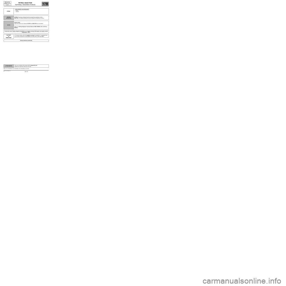
ET022LOW-SPEED FAN REQUEST–Active
–Inactive
STATUS
DEFINITIONACTIVE: This status indicates that the low-speed fan assembly is active.
INACTIVE: This status indicates that the low-speed fan assembly is inactive.
NOTESSpecial notes:
Apply the checks only if statuses ACTIVE and INACTIVE are inconsistent.
Refer to the Wiring Diagrams Technical Note for NEW TWINGO, E33, CLIO III or
MODUS.
Conformity check: Engine stopped and ignition on, or engine running at idle speed, and engine coolant
temperature > 80˚C.
"ACTIVE"
or
"INACTIVE"To ensure cooling, when the engine is running, fan assembly 1 is activated when
the coolant temperature exceeds 99˚C and stops when it falls below 96˚C.
Sensor electrical conformity
SIM32_V44_ET022/SIM32_V4C_ET022/SIM32_V50_ET022/SIM32_V54_ET022
AFTER REPAIRCarry out a road test, then check with the diagnostic tool.
Repeat the conformity check from the start.