light RENAULT TWINGO RS 2009 2.G Engine And Peripherals Passenger Compartment Connection Unit OBD Manual PDF
[x] Cancel search | Manufacturer: RENAULT, Model Year: 2009, Model line: TWINGO RS, Model: RENAULT TWINGO RS 2009 2.GPages: 179, PDF Size: 0.57 MB
Page 141 of 179
87B -141
MR-413-X44-87B000$624.mif
V5
UCH
Vdiag No.: 44PASSENGER COMPARTMENT CONNECTION UNIT
Fault finding - Interpretation of statuses87B
AFTER REPAIRRepeat the conformity check from the start.
Carry out fault finding on the system.
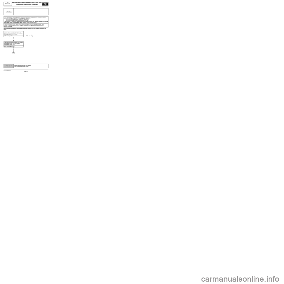
Special feature: Depending on the vehicle equipment, an additional fuse and diode are present on the
wiring: ET463
CONTINUED 2
Check the insulation, continuity and the absence of interference resistance of the following connections:
Central door locking/warning switch check (component code 1391):
●Connection code 20AW between components 645 and 1391.
●Connection code 20M between components 645 and 1391.
If the connection or connections are faulty and there is a repair procedure (see Technical Note 6015A, Electrical
wiring repair, Wiring: Precautions for repair), repair the wiring, otherwise replace it.
If the connections are correct, replace the central door locking/warning switch (component code 1391).
(See MR 411 Mechanical 84A, Control - Signals, Hazard warning lights and central door locking:
Removal - Refitting).
With the engine running, check that the door
open warning (buzzer) is active when the driver
door is open and the lights are on.
Is the warning active?
NO
Check the continuity of connection H24 between
components 140 and 1016 and between
components 119 and 1016.
Is the continuity correct?
NO
C
YESB
Page 143 of 179
87B -143
MR-413-X44-87B000$624.mif
V5
UCH
Vdiag No.: 44PASSENGER COMPARTMENT CONNECTION UNIT
Fault finding - Interpretation of statuses87B
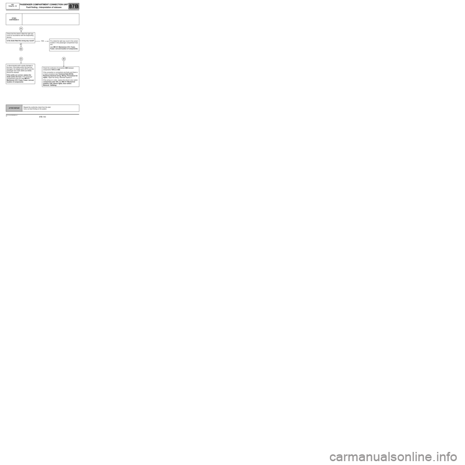
ET463
CONTINUED 4
Check that the diode is fitted the right way
round (in accordance with the foolproofing
device).
Is the diode fitted the wrong way round?
Fit a diode the right way round in the correct
location in the passenger compartment fuse
box.
(see MR 411 Mechanical, 81C, Fuses,
Fuses: List and location of components)
A disconnected earth causes damage to
the fuse. If the diode and/or the fuse are
damaged, the tailgate earth (MYH) and the
passenger door earth (MAN and MAM)
should be checked.
If the earths are correct, replace the
diode and/or the fuse in the passenger
compartment fuse box (see MR 411
Mechanical, 81C, Fuses, Fuses: List and
location of components)Check the continuity of connection 86H between
components 1016 and 645.
If the connection or connections are faulty and there is
a repair procedure (see Technical Note 6015A,
Repairing electrical wiring, Wiring: Precautions for
repair), repair the wiring, otherwise replace it.
If the wiring is in order, replace the driver's door switch
(component code 140) (see MR 411 Mechanical
systems, 81B, Interior lights, Door switch:
Removal - Refitting)
A
YES
NO
B
DB
AFTER REPAIRRepeat the conformity check from the start.
Carry out fault finding on the system.
Page 154 of 179
87B -154
MR-413-X44-87B000$816.mif
V5
PASSENGER COMPARTMENT CONNECTION UNIT
Fault finding - Interpretation of commands
UCH
Vdiag No.: 44
87B
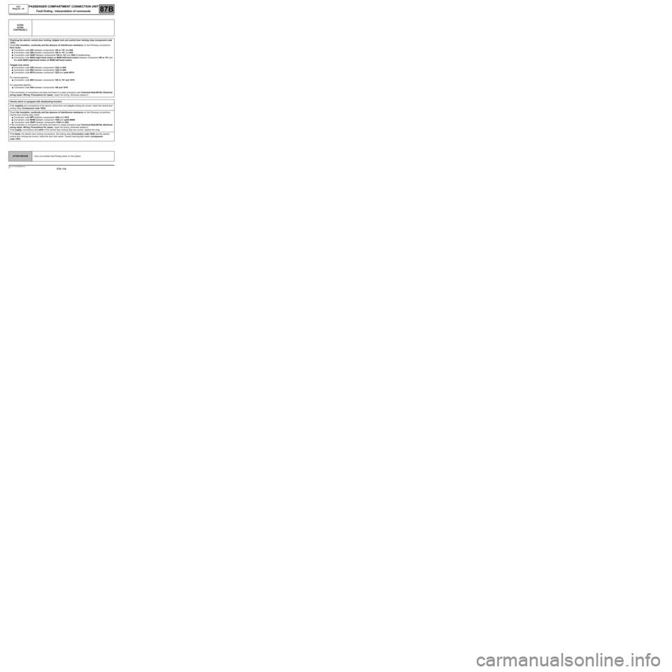
AC004
AC005
CONTINUED 2
Checking the electric central door locking, tailgate lock and central door locking relay (component code
1322):
Check the insulation, continuity and the absence of interference resistance on the following connections:
Door locks:
●Connection code 20C between components 140 or 141 and 645.
●Connection code 20D between components 140 or 141 and 645.
●Connection code 20AP between components 140 or 141 and 1042 (if deadlocking).
●Connection code MAN (right-hand motor) or MAM (left-hand motor) between component 140 or 141 and
the earth MAN (right-hand motor) or MAM (left-hand motor).
Tailgate lock check:
●Connection code 20S between components 1322 or 645.
●Connection code 86H between components 1322 or 645.
●Connection code MYH between component 1322 and earth MYH.
For manual gearbox:
●Connection code 86H between components 140 or 141 and 1016.
For sequential gearbox:
●Connection code H24 between components 140 and 1016.
If the connection or connections are faulty and there is a repair procedure (see Technical Note 6015A, Electrical
wiring repair, Wiring: Precautions for repair), repair the wiring, otherwise replace it.
Vehicle which is equipped with deadlocking function:
If the supplies and connections of the electric central door and tailgate locking are correct, check the central door
locking relay (Component code 1042).
Check the insulation, continuity and the absence of interference resistance on the following connections:
Central door locking relay check:
●Connection code BP3 between components 1042 and 1016.
●Connection code MAM between component 1042 and earth MAM.
●Connection code 20AP between components 1042 and 645.
If the connection or connections are faulty and there is a repair procedure (see Technical Note 6015A, Electrical
wiring repair, Wiring: Precautions for repair), repair the wiring, otherwise replace it.
If the supply, connections and earth of the central door locking relay are correct, replace the relay.
If the feeds, the electric door locking connections, the locking relay (Connection code 1042) and the electric
central door locking are correct, check the door lock switch / hazard warning light switch (component
code 1391).
AFTER REPAIRCarry out another fault finding check on the system.
Page 155 of 179
87B -155
MR-413-X44-87B000$816.mif
V5
PASSENGER COMPARTMENT CONNECTION UNIT
Fault finding - Interpretation of commands
UCH
Vdiag No.: 44
87B
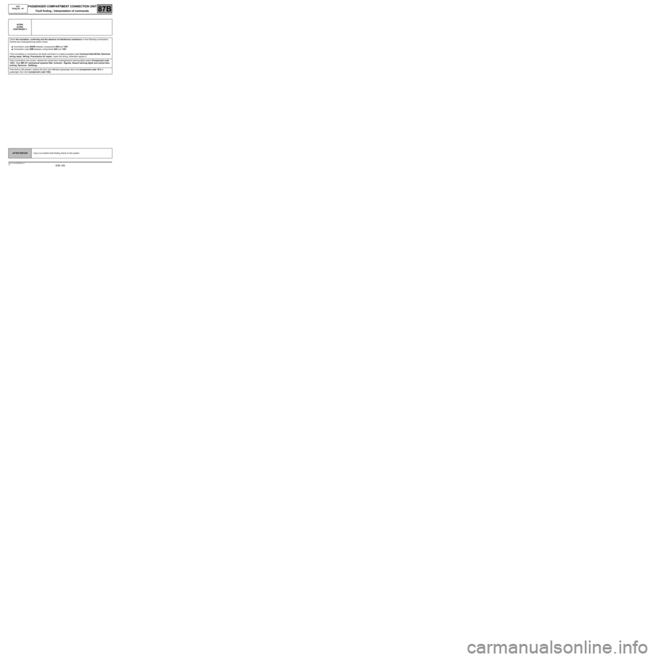
AC004
AC005
CONTINUED 3
Check the insulation, continuity and the absence of interference resistance on the following connections:
Central door locking/warning switch check:
●Connection code 20AW between components 645 and 1391.
●Connection code 20M between components 645 and 1391.
If the connection or connections are faulty and there is a repair procedure (see Technical Note 6015A, Electrical
wiring repair, Wiring: Precautions for repair), repair the wiring, otherwise replace it.
If the connections are correct, replace the central door locking/hazard warning lights switch (Component code
1391). (See MR 411 mechanical systems 84A, Controls - Signals, Hazard warning lights and central door
locking: Removal - Refitting).
If the fault is still present, replace the door lock affected (passenger door lock (component code 141) or
passenger door lock (component code 140)).
AFTER REPAIRCarry out another fault finding check on the system.
Page 158 of 179
87B -158
MR-413-X44-87B000$816.mif
V5
PASSENGER COMPARTMENT CONNECTION UNIT
Fault finding - Interpretation of commands
UCH
Vdiag No.: 44
87B
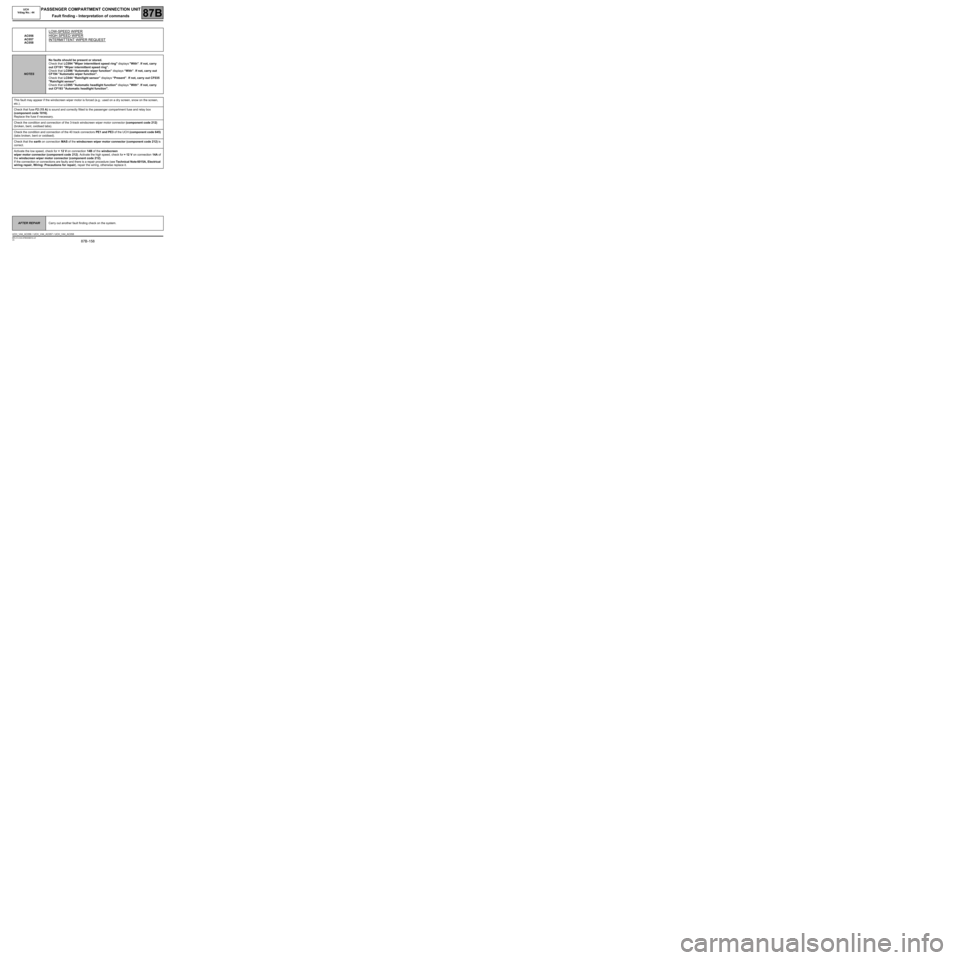
AC056
AC057
AC058
LOW-SPEED WIPER
HIGH SPEED WIPER
INTERMITTENT WIPER REQUEST
NOTESNo faults should be present or stored.
Check that LC094 "Wiper intermittent speed ring" displays "With". If not, carry
out CF191 “Wiper intermittent speed ring”.
Check that LC096 “Automatic wiper function” displays “With”. If not, carry out
CF194 "Automatic wiper function".
Check that LC044 “Rain/light sensor” displays “Present”. If not, carry out CF035
"Rain/light sensor".
Check that LC095 "Automatic headlight function" displays "With". If not, carry
out CF193 "Automatic headlight function".
This fault may appear if the windscreen wiper motor is forced (e.g.: used on a dry screen, snow on the screen,
etc.).
Check that fuse F2 (15 A) is sound and correctly fitted to the passenger compartment fuse and relay box
(component code 1016).
Replace the fuse if necessary.
Check the condition and connection of the 3-track windscreen wiper motor connector (component code 212)
(broken, bent, oxidised tabs).
Check the condition and connection of the 40 track connectors PE1 and PE3 of the UCH (component code 645)
(tabs broken, bent or oxidised).
Check that the earth on connection MAS of the windscreen wiper motor connector (component code 212) is
correct.
Activate the low speed, check for + 12 V on connection 14B of the windscreen
wiper motor connector (component code 212). Activate the high speed, check for + 12 V on connection 14A of
the windscreen wiper motor connector (component code 212).
If the connection or connections are faulty and there is a repair procedure (see Technical Note 6015A, Electrical
wiring repair, Wiring: Precautions for repair), repair the wiring, otherwise replace it.
AFTER REPAIRCarry out another fault finding check on the system.
UCH_V44_AC056 / UCH_V44_AC057 / UCH_V44_AC058
Page 164 of 179
87B -164
MR-413-X44-87B000$864.mif
V5
87B
PASSENGER COMPARTMENT CONNECTION UNIT
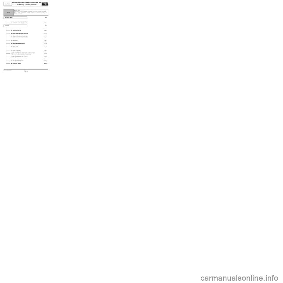
Fault finding - Customer complaints
NOTESSpecial notes:
This summary corresponds to the complete list of customer complaints for a UCH.
These customer complaints are divided by function in the section corresponding to the
function concerned.
DIALOGUE FAULT87B
NO DIALOGUE WITH THE COMPUTER ALP 1
LIGHTING80D
NO REAR FOG LIGHTS ALP 2
NO RIGHT-HAND DIRECTION INDICATOR ALP 3
NO LEFT-HAND DIRECTION INDICATOR ALP 4
NO SIDE LIGHTS ALP 5
NO DIPPED BEAM HEADLIGHTS ALP 6
NO HEADLIGHTS ALP 7
NO FRONT FOG LIGHTS ALP 8
LIGHTS DO NOT SWITCH OFF AFTER + AFTER IGNITION
FEED IS CUT AND DRIVER'S DOOR IS OPENEDALP 9
LIGHTS DO NOT SWITCH ON AT NIGHT ALP 10
NO SEE-ME-HOME LIGHTING ALP 11
NO COURTESY LIGHTS ALP 12
MR-413-X44-87B000$864.mif
UCH
Vdiag No.: 44
Page 166 of 179
87B -166
MR-413-X44-87B000$864.mif
V5
UCH
Vdiag No.: 44PASSENGER COMPARTMENT CONNECTION UNIT
Fault finding - Customer complaints87B
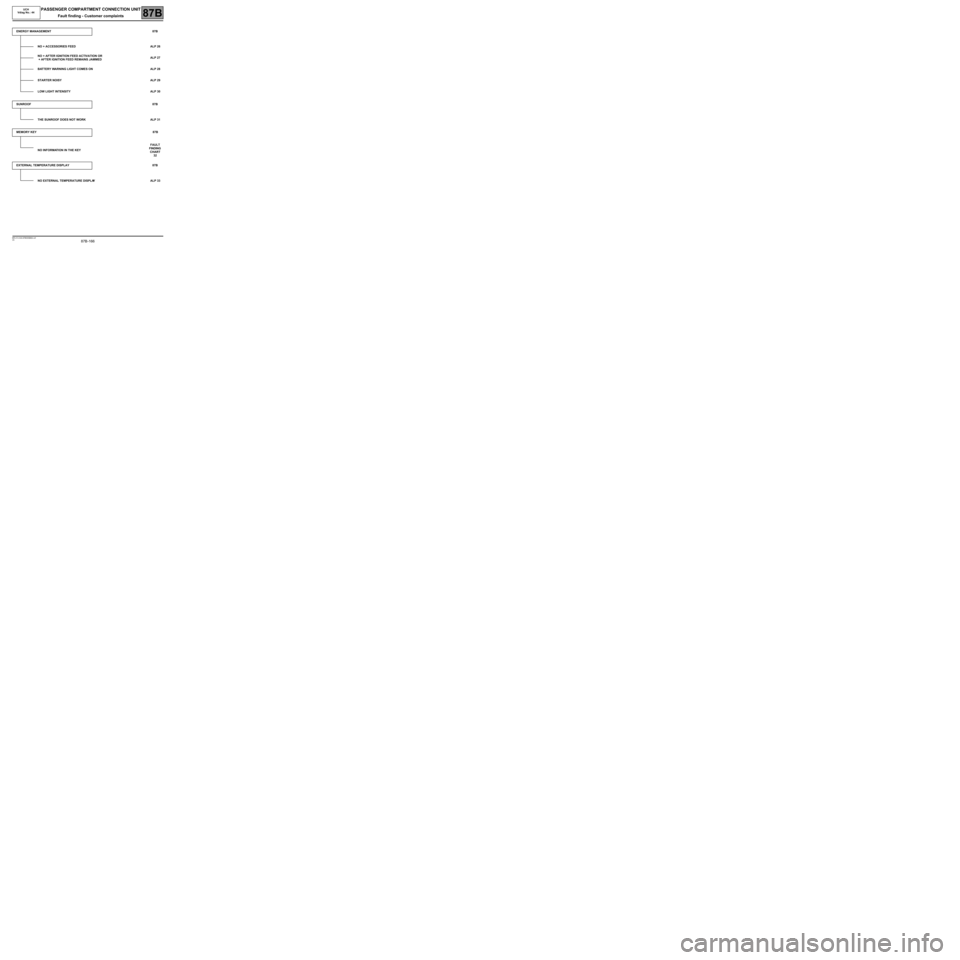
ENERGY MANAGEMENT87B
NO + ACCESSORIES FEED ALP 26
NO + AFTER IGNITION FEED ACTIVATION OR
+ AFTER IGNITION FEED REMAINS JAMMEDALP 27
BATTERY WARNING LIGHT COMES ON ALP 28
STARTER NOISY ALP 29
LOW LIGHT INTENSITY ALP 30
SUNROOF87B
THE SUNROOF DOES NOT WORK ALP 31
MEMORY KEY87B
NO INFORMATION IN THE KEYFAULT
FINDING
CHART
32
EXTERNAL TEMPERATURE DISPLAY 87B
NO EXTERNAL TEMPERATURE DISPLAYALP 33
Page 169 of 179
87B -169
MR-413-X44-87B000$912.mif
V5
PASSENGER COMPARTMENT CONNECTION UNIT
Fault finding - Fault Finding Chart
UCH
Vdiag No.: 44
87B
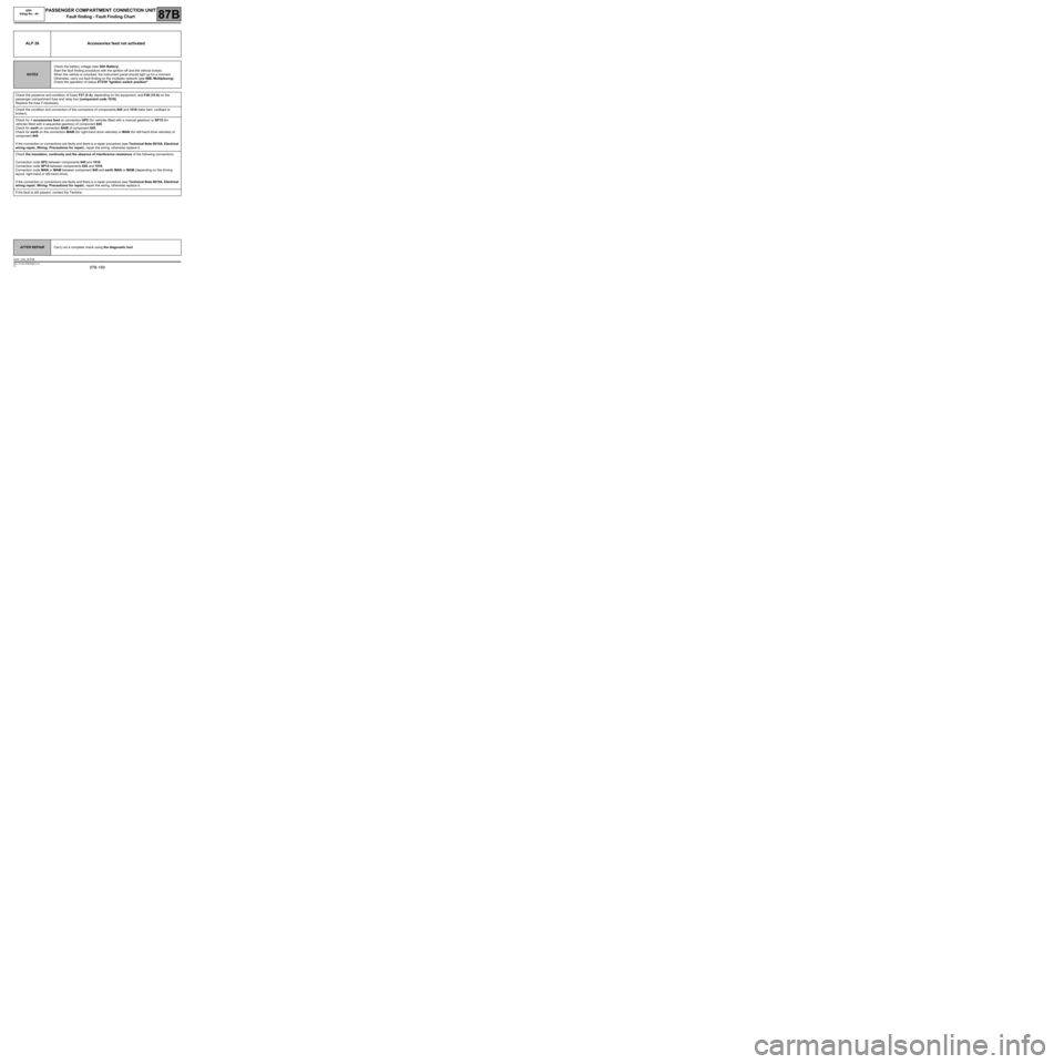
ALP 26 Accessories feed not activated
NOTESCheck the battery voltage (see 80A Battery).
Start the fault finding procedure with the ignition off and the vehicle locked.
When the vehicle is unlocked, the instrument panel should light up for a moment.
Otherwise, carry out fault finding on the multiplex network (see 88B, Multiplexing).
Check the operation of status ET239 "Ignition switch position".
Check the presence and condition of fuses F27 (5 A), depending on the equipment, and F29 (15 A) on the
passenger compartment fuse and relay box (component code 1016).
Replace the fuse if necessary.
Check the condition and connection of the connectors of components 645 and 1016 (tabs bent, oxidised or
broken).
Check for + accessories feed on connection SP2 (for vehicles fitted with a manual gearbox) or SP15 (for
vehicles fitted with a sequential gearbox) of component 645.
Check for earth on connection NAM of component 645.
Check for earth on the connection MAM (for right-hand drive vehicles) or MAN (for left-hand drive vehicles) of
component 645.
If the connection or connections are faulty and there is a repair procedure (see Technical Note 6015A, Electrical
wiring repair, Wiring: Precautions for repair), repair the wiring, otherwise replace it.
Check the insulation, continuity and the absence of interference resistance of the following connections:
Connection code SP2 between components 645 and 1016.
Connection code SP15 between components 645 and 1016.
Connection code MAN or MAM between component 645 and earth MAN or MAM (depending on the driving
layout; right-hand or left-hand drive).
If the connection or connections are faulty and there is a repair procedure (see Technical Note 6015A, Electrical
wiring repair, Wiring: Precautions for repair), repair the wiring, otherwise replace it.
If the fault is still present, contact the Techline.
AFTER REPAIRCarry out a complete check using the diagnostic tool.
UCH_V44_ALP26
Page 171 of 179
87B -171
MR-413-X44-87B000$912.mif
V5
PASSENGER COMPARTMENT CONNECTION UNIT
Fault finding - Fault Finding Chart
UCH
Vdiag No.: 44
87B
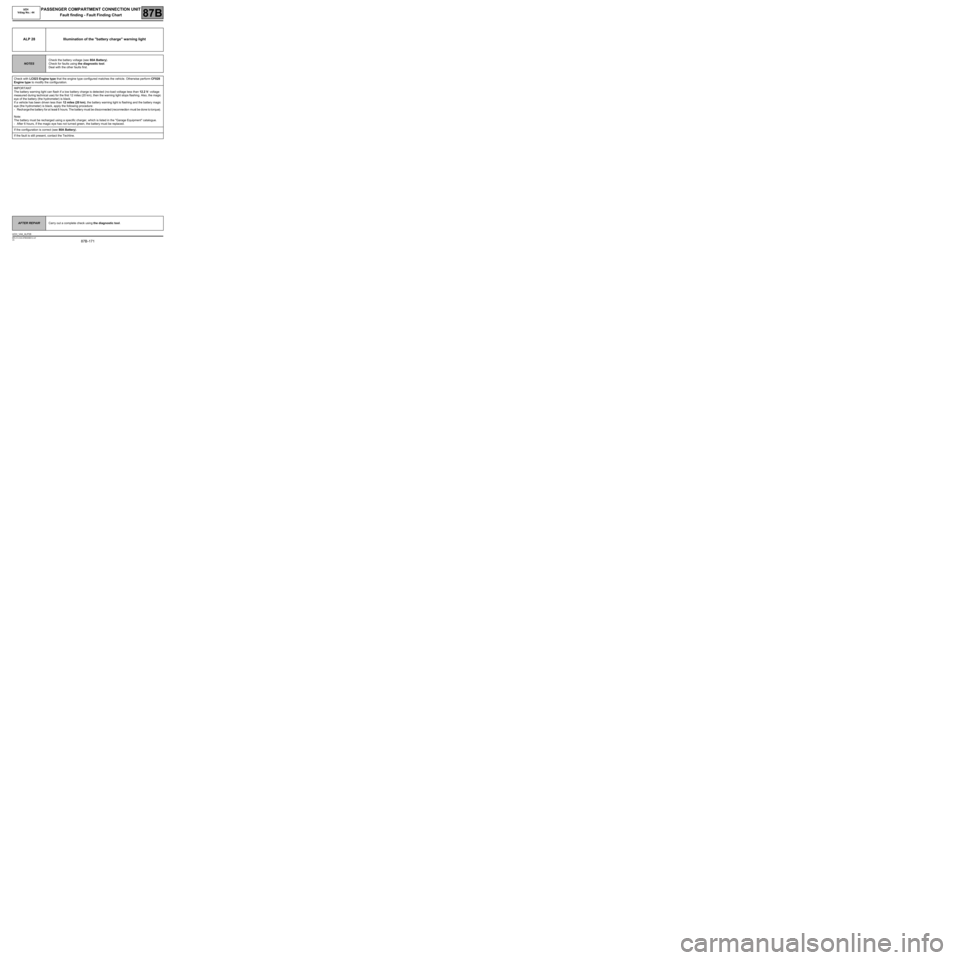
ALP 28 Illumination of the "battery charge" warning light
NOTESCheck the battery voltage (see 80A Battery).
Check for faults using the diagnostic tool.
Deal with the other faults first.
Check with LC023 Engine type that the engine type configured matches the vehicle. Otherwise perform CF028
Engine type to modify the configuration.
IMPORTANT
The battery warning light can flash if a low battery charge is detected (no-load voltage less than 12.2 V: voltage
measured during technical use) for the first 12 miles (20 km), then the warning light stops flashing. Also, the magic
eye of the battery (the hydrometer) is black.
If a vehicle has been driven less than 12 miles (20 km), the battery warning light is flashing and the battery magic
eye (the hydrometer) is black, apply the following procedure:
-Recharge the battery for at least 6 hours. The battery must be disconnected (reconnection must be done to torque).
Note:
The battery must be recharged using a specific charger, which is listed in the "Garage Equipment" catalogue.
-After 6 hours, if the magic eye has not turned green, the battery must be replaced.
If the configuration is correct (see 80A Battery).
If the fault is still present, contact the Techline.
AFTER REPAIRCarry out a complete check using the diagnostic tool.
UCH_V44_ALP28
Page 173 of 179
87B -173
MR-413-X44-87B000$912.mif
V5
PASSENGER COMPARTMENT CONNECTION UNIT
Fault finding - Fault Finding Chart
UCH
Vdiag No.: 44
87B
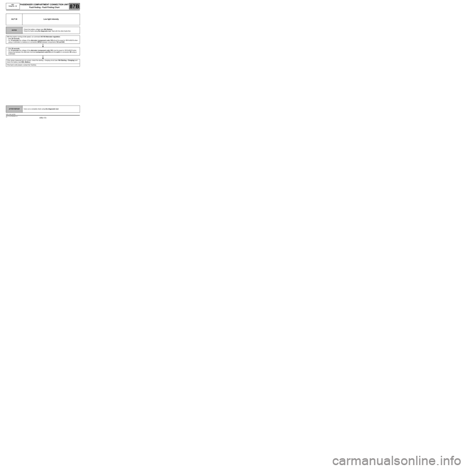
ALP 30 Low light intensity
NOTESCheck the battery voltage (see 80A Battery).
Check for faults using the diagnostic tool. Deal with the other faults first.
With the engine running at idle speed, run command AC130 Alternator regulation.
–Wait 20 seconds.
–For 10 seconds the voltage of the alternator (component code 103) should be equal to 15 V ± 0.2 V, when
using a multimeter to measure on connection BPDA between components 103 and 645.
–Wait 20 seconds.
–For 10 seconds the voltage of the alternator (component code 103) must be equal to 13 V ± 0.2 V when
measuring between the alternator terminal (component code103) and the earth on connection 2N using a
multimeter.
If the values measured are not correct, check the starting - charging circuit (see 16A Starting - Charging) and
check the battery (see 80A, Battery).
If the fault is still present, contact the Techline.
AFTER REPAIRCarry out a complete check using the diagnostic tool.
UCH_V44_ALP30