oil filter RENAULT TWINGO RS 2009 2.G Engine And Peripherals Manual Online
[x] Cancel search | Manufacturer: RENAULT, Model Year: 2009, Model line: TWINGO RS, Model: RENAULT TWINGO RS 2009 2.GPages: 652
Page 471 of 652

17A-15
IGNITION
Plugs: Removal - Refitting
D4F, and 780 – D4F, and 782
17A
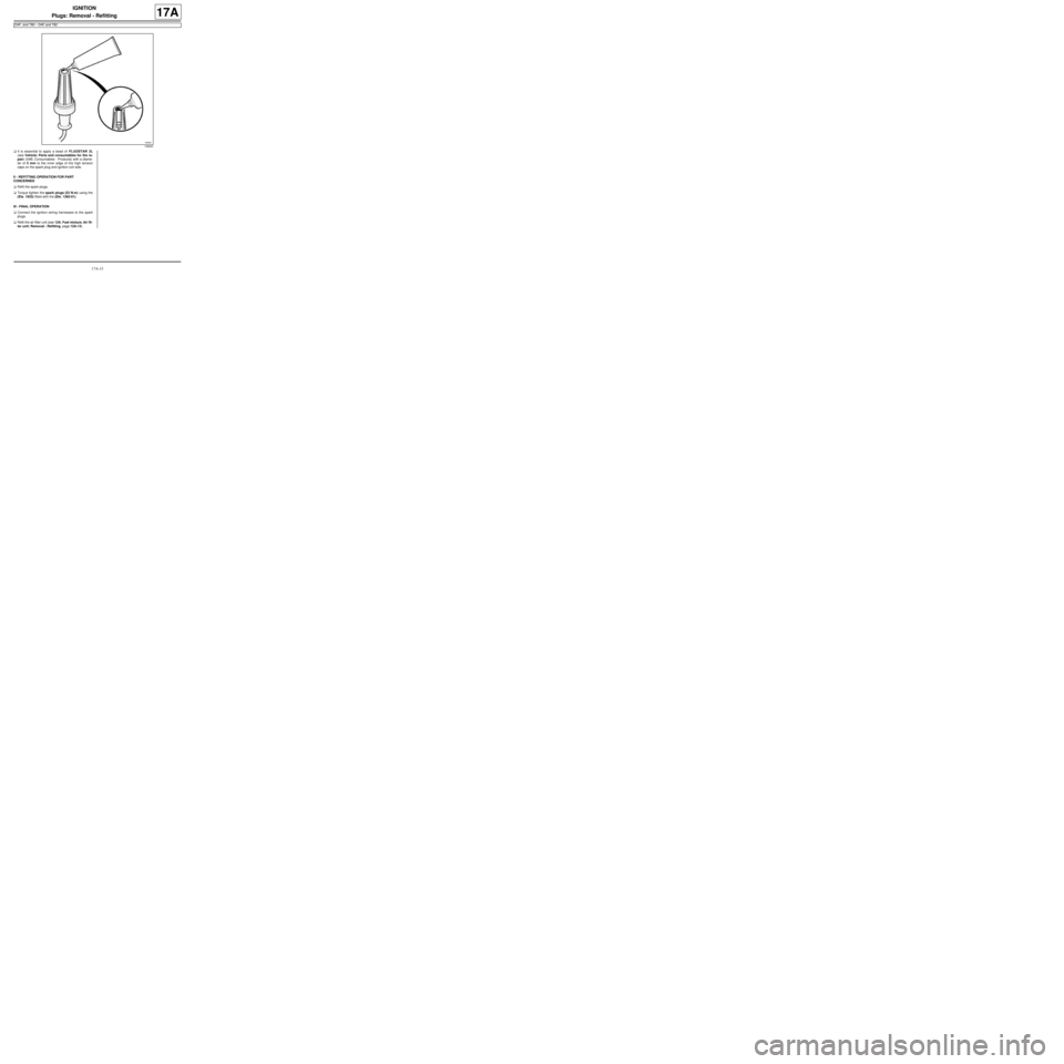
aIt is essential to apply a bead of FLUOSTAR 2L
(see Vehicle: Parts and consumables for the re-
pair) (04B, Consumables - Products) with a diame-
ter of 2 mm to the inner edge of the high tension
caps on the spark plug and ignition coil side.
II - REFITTING OPERATION FOR PART
CONCERNED
aRefit the spark plugs.
aTorque tighten the spark plugs (23 N.m) using the
(Ele. 1933) fitted with the (Ele. 1382-01).
III - FINAL OPERATION
aConnect the ignition wiring harnesses to the spark
plugs.
aRefit the air filter unit (see 12A, Fuel mixture, Air fil-
ter unit: Removal - Refitting, page 12A-13) .
106640
Page 507 of 652

17B-32
PETROL INJECTION
Injector rail - Injectors: Removal - Refitting
D4F, and 780 or 782
17B
REFITTING
I - REFITTING PREPARATION OPERATION
aparts always to be replaced: injector clip on in-
jector rail.
aparts always to be replaced: injector seal.
II - REFITTING OPERATION FOR PART
CONCERNED
aRefit:
-the injectors with new seals,
-new clips on the injectors,
-the injector rail - injector electrical wiring.
aConnect the connectors of the electrical wiring to the
injectors.
aRefit:
-the « injector rail - injector » assembly,
-the « injector rail - injector » assembly bolts.
aTorque tighten the injector rail - injector bolts (4.5
N.m).
aConnect:
-the fuel supply pipe on the injector rail,
-the electrical wiring connector to the injector rail,
-the oil vapour rebreathing pipe on the inlet distribu-
tor.
aRefit the dipstick.
III - FINAL OPERATION
aFit the petrol vapour rebreathing pipe.
aClip on the petrol vapour rebreathing pipe.
aConnect the petrol vapour rebreathing pipe to:
-the air outlet pipe of the air filter unit,
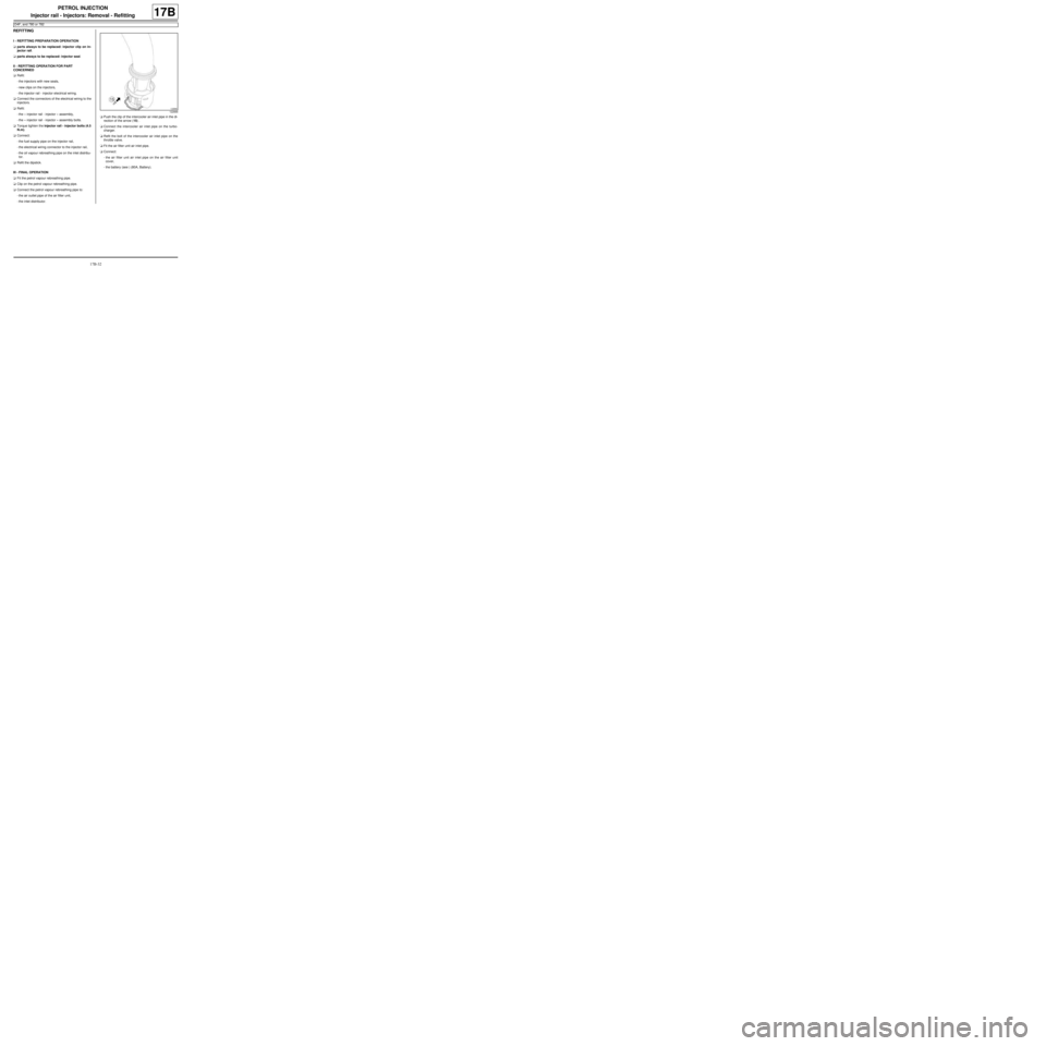
-the inlet distributor.aPush the clip of the intercooler air inlet pipe in the di-
rection of the arrow (15) .
aConnect the intercooler air inlet pipe on the turbo-
charger.
aRefit the bolt of the intercooler air inlet pipe on the
throttle valve.
aFit the air filter unit air inlet pipe.
aConnect:
-the air filter unit air inlet pipe on the air filter unit
cover,
-the battery (see ) (80A, Battery).
122666
Page 520 of 652

19A-10
COOLING
Cooling system: Draining - Refilling
D4F or D7F or K4M or K9K
19A
2 - Filling method without special tools
a
aRemove the air filter unit (see 12A, Fuel mixture,
Air filter unit: Removal - Refitting, page 12A-13) .
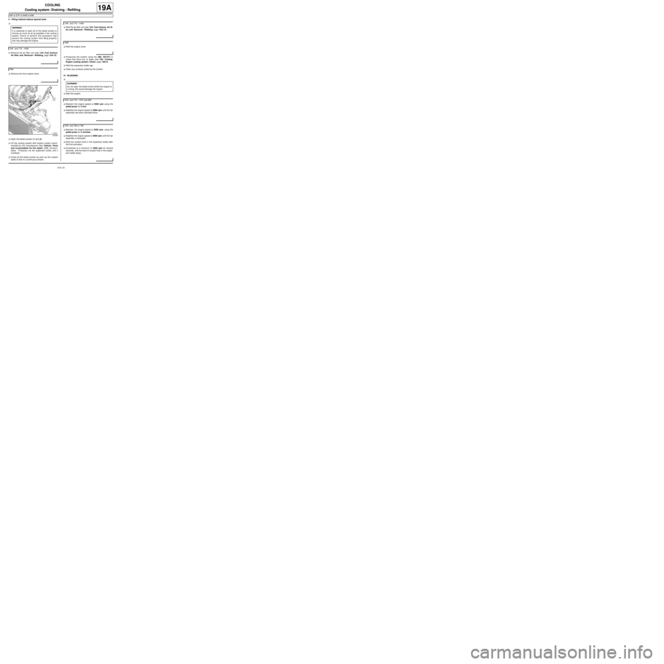
aRemove the front engine cover.
aOpen the bleed screws (1) and (2) .
aFill the cooling system with engine coolant recom-
mended by the manufacturer (see Vehicle: Parts
and consumables for the repair) (04B, Consum-
ables - Products) via the expansion bottle until it
overflows.
aClose all the bleed screws as soon as the coolant
starts to flow in a continuous stream.aRefit the air filter unit (see 12A, Fuel mixture, Air fil-
ter unit: Removal - Refitting, page 12A-13) .
aRefit the engine cover.
aPressurise the system using the (Ms. 554-07) to
check that there are no leaks (see 19A, Cooling,
Engine cooling system: Check, page 19A-2) .
aRefit the expansion bottle cap.
aClean any surfaces soiled by the coolant.
IV - BLEEDING
a
aStart the engine.
aMaintain the engine speed at 2500 rpm using the
pedal press for 5 min.
aStabilise the engine speed at 2000 rpm until the fan
assembly has been activated twice.
aMaintain the engine speed at 2500 rpm, using the
pedal press for 5 minutes.
aStabilise the engine speed at 2000 rpm until the fan
assembly is activated.
aNote the coolant level in the expansion bottle after
this first activation.
aAccelerate at a minimum of 4000 rpm for several
seconds, until the level of coolant fluid in the expan-
sion bottle drops. WARNING
It is essential to open all of the bleed screws to
remove as much as air as possible in the cooling
system. Failure to perform this procedure may
prevent the cooling system from filling properly
and may damage the engine.
D4F, and 772 – K4M
K9K
120526
D4F, and 772 – K4M
K9K
WARNING
Do not open the bleed screw whilst the engine is
running; this would damage the engine.
D4F, and 772 – D7F, and 800
D4F, and 780 or 782
Page 596 of 652

19B-14
EXHAUST
Catalytic converter: Removal - Refitting
K9K
19B
aIf they are replaced, torque tighten the catalytic
converter studs on the turbocharger (9 Nm ).
II - REFITTING OPERATION FOR PART
CONCERNED
aFrom underneath the vehicle, fit:
-the catalytic converter on the turbocharger fitted
with a new seal between the catalytic converter
and the turbocharger,
-one of the catalytic converter nuts on the turbo-
charger.
aIn order, fit (without tightening):
-the catalytic converter upstream strut bolts on the
engine,
-the catalytic converter downstream strut bolt and
nut on the gearbox,
-the catalytic converter upstream strut bolts on the
catalytic converter,
-the catalytic converter downstream strut bolt on the
catalytic converter,
-the catalytic converter nuts on the turbocharger,
aTorque tighten and in order:
-the catalytic converter nuts on the turbocharger
(26 Nm),
-the catalytic converter upstream strut bolts on
the engine (44 Nm),
-the catalytic converter downstream strut bolts
on the gearbox (21 Nm),
-the catalytic converter downstream strut nut on
the gearbox (21 Nm),
-the catalytic converter upstream strut bolts on
the catalytic converter (26 Nm),
-the catalytic converter downstream strut bolt
on the catalytic converter (21 Nm).
aFit in order:
-a new exhaust system sealing ring on the catalytic
converter,
-the exhaust pipe on the catalytic converter,
-the exhaust pipe springs and bolts on the catalytic
converter.aTorque tighten the exhaust pipe bolts on the cata-
lytic converter (21 Nm).
aCheck the following and deal with if necessary:
-that there is no contact with the underbody,
-the presence and correct positioning of all the ex-
haust pipe heat shields.
III - FINAL OPERATION.
aRefit:
-the engine tie-bar (see 19D, Engine mounting,
Lower engine tie-bar: Removal - Refitting, page
19D-18) ,
-the air filter box (see 12A, Fuel mixture, Air filter
unit: Removal - Refitting, page 12A-13) ,
-the scoop under the scuttle panel grille ( (see
Scoop under the scuttle panel grille: Removal -
Refitting) ),
-the scuttle panel grille ( (see Scuttle panel grille:
Removal - Refitting) ),
-the windscreen wiper arms ( (see Windscreen
wiper arm: Removal - Refitting) ).
aConnect the battery ( (see Battery: Removal - Re-
fitting) ).
aStart the engine.
aCheck that there are no leaks and deal with them if
necessary. Note:
Check that there is no contact between the cata-
lytic conver ter and the turbocharger oil return
pipe during the entire catalytic converter tighten-
ing operation.