relay RENAULT TWINGO RS 2009 2.G Engine And Peripherals Workshop Manual
[x] Cancel search | Manufacturer: RENAULT, Model Year: 2009, Model line: TWINGO RS, Model: RENAULT TWINGO RS 2009 2.GPages: 652
Page 12 of 652
10A-6
ENGINE AND CYLINDER BLOCK ASSEMBLY
Lower cover: Removal - Refitting
K9K
10A
REMOVAL
I - REMOVAL PREPARATION OPERATION
aPosition the vehicle on a two-post lift (see Vehicle:
Towing and lifting) (02A, Lifting equipment).
aRemove:
-the front wheels (see Wheel: Removal - Refitting)
(35A, Wheels and tyres),
-the front wheel arch liners (see Front wheel arch
liner: Removal - Refitting) (55A, Exterior protec-
tion),
-the front bumper (see Front bumper: Removal -
Refitting) (55A, Exterior protection). Special tooling required
Tav. 476Ball joint extractor.
Tav. 1233-01Tooling for carrying out opera-
tions on the axle subframe.
Equipment required
flywheel immobiliser
safety strap(s)
Tightening torquesm
lowe r cylinder block
bolts14 Nm
multifunction support
bolt on the sump25 N.m
sump bolts on the gear-
box casing44 Nm
subframe front bolts62 N.m
subframe rear bolts105 Nm
subframe rear tie rod
inner bolts21 N.m
subframe rear tie rod
outer bolts90 N.m
lower ball joint bolts62 N.m
track rod end nuts37 N.m
subframe tie-rod upper
bolts21 N.m
subframe tie-rod lower
bolts62 N.m
bolts of the front right-
hand driveshaft relay
bearing44 N.m
bolt of the front right-
hand driveshaft relay
bearing bracket21 N.m
relay bearing bolts on
the front right-hand
driveshaft44 N.m
right-hand driveshaft
relay bearing closure
panel bolts21 Nm
catalytic converter
upstream stay bolt on
the cylinder block44 N.m
catalytic converter
downstream stay bolt on
the sump44 Nm
catalytic converter
downstream stay bolts
on the catalytic con-
verter26 Nm
universal joint bolt24 N.m Tightening torquesm
Page 14 of 652
10A-8
ENGINE AND CYLINDER BLOCK ASSEMBLY
Lower cover: Removal - Refitting
K9K
10A
aRemove:
-the bolt (4) from the relay bearing flange,
-the bolts (5) from the relay bearing,
-the relay bearing.aRemove:
-the bolts (6) from the relay bearing,
-the bolts of the relay bearing closure panel,
-the relay bearing closure panel.
aPivot the relay bearing on the right-hand driveshaft
then slide it towards the gearbox. K9K, and 718
141225
K9K, and 740
120418
Page 18 of 652
10A-12
ENGINE AND CYLINDER BLOCK ASSEMBLY
Lower cover: Removal - Refitting
K9K
10A
-the subframe rear bolts (105 Nm),
-the subframe rear tie rod inner bolts (21 N.m),
-the subframe rear tie rod outer bolts (90 N.m).
aRefit the radiator mounting cross member (see Ra-
diator mounting cross member: Removal - Refit-
ting) (41A, Front lower structure).
aDetach the radiator and the intercooler from the up-
per cross member using a safety strap(s).
aDetach the radiator from the upper cross member
using a safety strap(s).
aRefit:
-the rear engine tie-bar (see 19D, Engine mount-
ing, Lower engine tie-bar: Removal - Refitting,
page 19D-18) ,
-the lower ball joints,
-the track rod ends.
aTighten to torque:
-the lower ball joint bolts (62 N.m),
-the track rod end nuts (37 N.m).
aRefit the subframe tie rod upper bolts.
aTighten to torque:
-the subframe tie-rod upper bolts (21 N.m),
-the subframe tie-rod lower bolts (62 N.m).
aRefit the front right-hand driveshaft relay bearing
aTighten to torque:
-the bolts of the front right-hand driveshaft relay
bearing (44 N.m),
-the bolt of the front right-hand driveshaft relay
bearing bracket (21 N.m).aFit the relay bearing on its bearing on the front right-
hand driveshaft.
aTorque tighten the relay bearing bolts on the front
right-hand driveshaft (44 N.m).
aRefit the closure panel of the front right-hand drive-
shaft relay bearing
aTorque tighten the right-hand driveshaft relay
bearing closure panel bolts (21 Nm).
aRefit the catalytic converter upstream stay, by slid-
ing it in relation to the bolt remaining on the sump.
aTighten the following until contact is made and to tor-
que:
-the catalytic converter upstream stay bolt on
the cylinder block (44 N.m),
-the catalytic converter downstream stay bolt on
the sump (44 Nm),
-the catalytic converter downstream stay bolts
on the catalytic converter (26 Nm).
aFit the steering box universal joint equipped with a
new bolt.
aTorque tighten the universal joint bolt (24 N.m).
aRemove the flywheel immobiliser.
aRefit:
-the front bumper (see Front bumper: Removal -
Refitting) (55A, Exterior protection),
-the front wheel arch liners (see Front wheel arch
liner: Removal - Refitting) (55A, Exterior protec-
tion),
-the front wheels (see Wheel: Removal - Refitting)
(35A, Wheels and tyres).
aFill up the engine oil (see 10A, Engine and cylinder
block assembly, Engine oil: Draining - Refilling,
page 10A-22) . K9K, and 718
K9K, and 740
K9K, and 718
K9K, and 740
Note:
Ensure that the right-hand dr iveshaft relay bear-
ing closure panel is refi tted the right way round.
Page 24 of 652
10A-18
ENGINE AND CYLINDER BLOCK ASSEMBLY
Lower cover: Removal - Refitting
K4M
10A
REMOVAL
I - REMOVAL PREPARATION OPERATION
aPosition the vehicle on a two-post lift (see Vehicle:
Towing and lifting) (02A, Lifting equipment).
aRemove:
-the dipstick,
-the front wheels (see Wheel: Removal - Refitting)
(35A, Wheels and tyres),
-the engine undertray.
aDrain the engine oil (see 10A, Engine and cylinder
block assembly, Engine oil: Draining - Refilling,
page 10A-22) .
aRemove:
-the front wheel arch liners (see Front wheel arch
liner: Removal - Refitting) (55A, Exterior protec-
tion),
-the front bumper (see Front bumper: Removal -
Refitting) (55A, Exterior protection),-the rear engine tie-bar (see 19D, Engine mount-
ing, Lower engine tie-bar: Removal - Refitting,
page 19D-18) ,
-the front axle subframe (see Front axle subframe:
Removal - Refitting) (31A, Front axle compo-
nents).
aRemove:
-the front right-hand driveshaft flange bolt (1) on the
relay bearing,
-the bolts (2) from the front right-hand driveshaft re-
lay bearing,
-the front right-hand driveshaft relay bearing. Tightening torquesm
sump bolts (initial
torque)14 N.m
sump bolts14 N.m
sump bolts on the gear-
box44 N.m
bolt mounting the multi-
function support on the
sump25 N.m
catalytic pre-converter
upstream bracket bolt44 N.m
driveshaft relay bearing
bolts44 N.m.
right-hand driveshaft
bracket bolt on the relay
bearing21 N.m
IMPORTANT
Wear leaktight gloves (Nitrile type) for this opera-
tion.
128800
Page 27 of 652
10A-21
ENGINE AND CYLINDER BLOCK ASSEMBLY
Lower cover: Removal - Refitting
K4M
10A
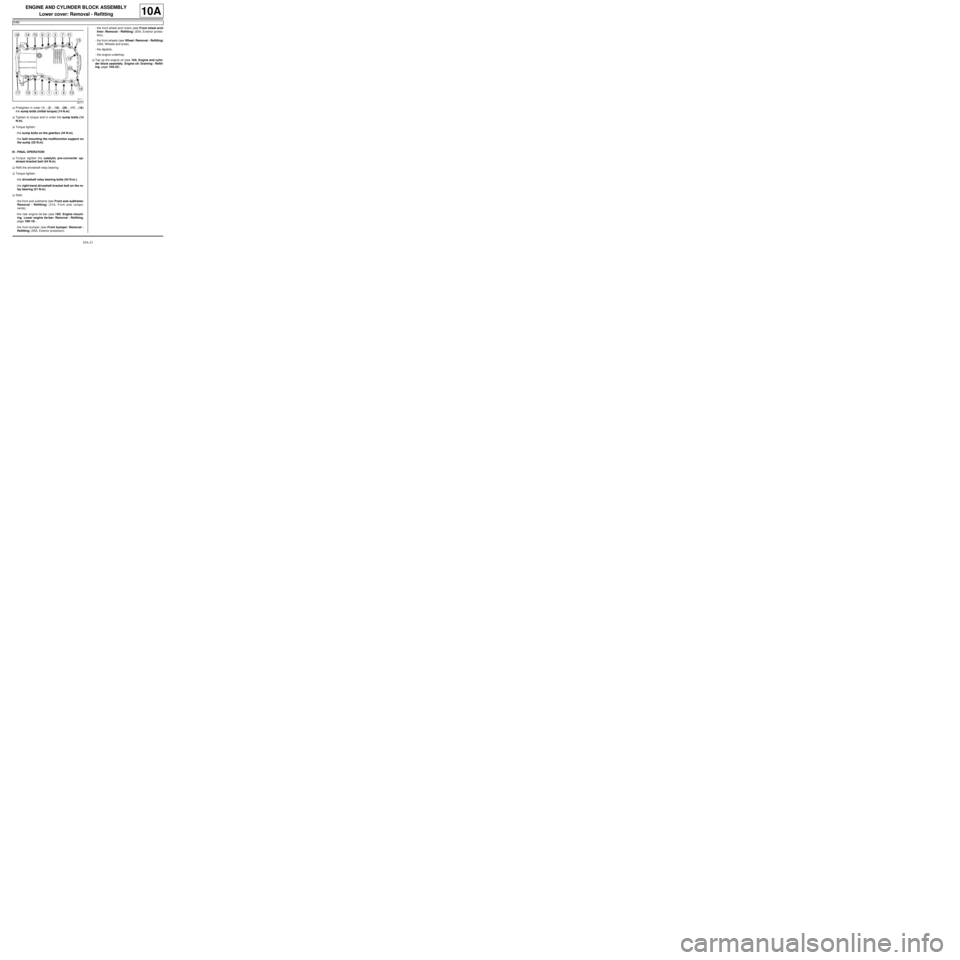
aPretighten in order (1) , (2) , (19) , (20) , (17) , (18)
the sump bolts (initial torque) (14 N.m).
aTighten to torque and in order the sump bolts (14
N.m).
aTorque tighten:
-the sump bolts on the gearbox (44 N.m),
-the bolt mounting the multifunction support on
the sump (25 N.m).
III - FINAL OPERATION
aTorque tighten the catalytic pre-converter up-
stream bracket bolt (44 N.m).
aRefit the driveshaft relay bearing.
aTorque tighten:
-the driveshaft relay bearing bolts (44 N.m.),
-the right-hand driveshaft bracket bolt on the re-
lay bearing (21 N.m).
aRefit:
-the front axle subframe (see Front axle subframe:
Removal - Refitting) (31A, Front axle compo-
nents),
-the rear engine tie-bar (see 19D, Engine mount-
ing, Lower engine tie-bar: Removal - Refitting,
page 19D-18) ,
-the front bumper (see Front bumper: Removal -
Refitting) (55A, Exterior protection),-the front wheel arch liners (see Front wheel arch
liner: Removal - Refitting) (55A, Exterior protec-
tion),
-the front wheels (see Wheel: Removal - Refitting)
(35A, Wheels and tyres),
-the dipstick,
-the engine undertray.
aTop up the engine oil (see 10A, Engine and cylin-
der block assembly, Engine oil: Draining - Refill-
ing, page 10A-22) .
20171
Page 43 of 652
10A-37
ENGINE AND CYLINDER BLOCK ASSEMBLY
Conrod bearing shell: Removal - Refitting
K9K
10A
REMOVAL
I - REMOVAL PREPARATION OPERATION
aPosition the vehicle on a two-post lift (see Vehicle:
Towing and lifting) (02A, Lifting equipment).
aRemove the engine undertray.
aDrain the oil from the engine (see 10A, Engine and
cylinder block assembly, Engine oil: Draining -
Refilling, page 10A-22) .
aRemove the oil filter (see 10A, Engine and cylinder
block assembly, Oil filter: Removal - Refitting,
page 10A-29) .
aRemove the lower engine tie-bar (see 19D, Engine
mounting, Lower engine tie-bar: Removal - Refit-
ting, page 19D-18) .
aStrap the radiator to the vehicle using safety
strap(s).
aRemove the front axle subframe (see Front axle
subframe: Removal - Refitting) (31A, Front axle
components).
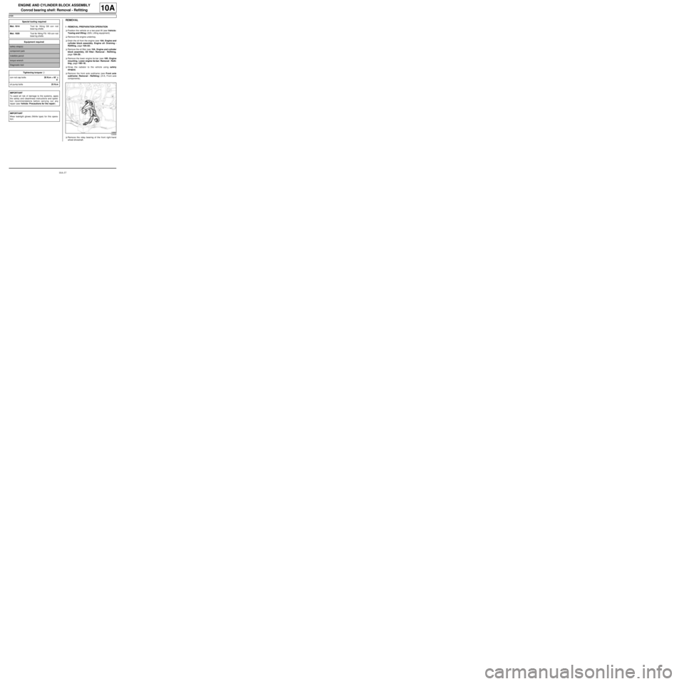
aRemove the relay bearing of the front right-hand
wheel driveshaft. Special tooling required
Mot. 1914Tool for fitting G9 con rod
bear ing shells
Mot. 1920Tool for fitting F9 / K9 con rod
bear ing shells
Equipment required
safety strap(s)
component jack
indelible pencil
torque wrench
Diagnostic tool
Tightening torquesm
con rod cap bolts20 N.m + 45˚ ±± ± ±
6˚
oil pump bolts25 N.m
IMPORTANT
To avoid all risk of damage to the systems, apply
the safety and cleanliness instructions and opera-
tion recommendations before carrying out any
repair (see Vehicle: Precautions for the repair) .
IMPORTANT
Wear leaktight gloves (Nitrile type) for this opera-
tion.
123838
Page 50 of 652
10A-44
ENGINE AND CYLINDER BLOCK ASSEMBLY
Conrod bearing shell: Removal - Refitting
K9K
10A
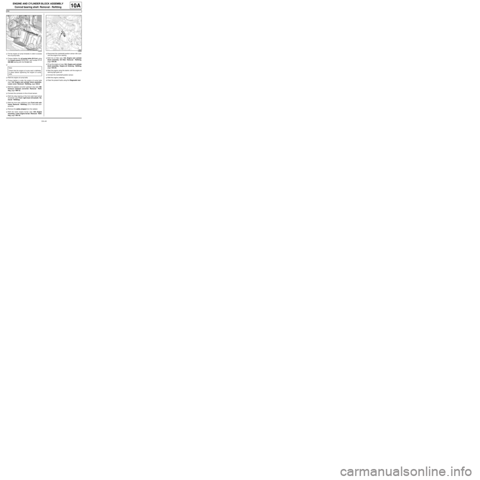
aTilt the engine oil sump forwards in order to access
the oil pump bolts.
aTorque tighten the oil pump bolts (25 N.m) using
the torque wrench PROSTEEL, part number 77 11
226 888 starting with the 13 mm bolt.
a
aRefit the engine oil sump bolts.
aTorque tighten in order the engine oil sump bolts
(see 10A, Engine and cylinder block assembly,
Lower cover: Removal - Refitting, page 10A-6) .
aRefit the catalytic converter upstream stay (see 19B,
Exhaust, Catalytic converter: Removal - Refit-
ting, page 19B-12) .
aConnect the connector to the oil level sensor.
aRefit the relay bearing of the front right-hand wheel
driveshaft (see Front right-hand driveshaft: Re-
moval - Refitting) .
aRefit the front axle subframe (see Front axle sub-
frame: Removal - Refitting) (31A, Front axle com-
ponents).
aRemove the safety strap(s) from the radiator.
aRefit the lower engine tie-bar (see 19D, Engine
mounting, Lower engine tie-bar: Removal - Refit-
ting, page 19D-18) .aDisconnect the crankshaft position sensor (4) to pre-
vent the engine from starting.
aRefit the oil filter (see 10A, Engine and cylinder
block assembly, Oil filter: Removal - Refitting,
page 10A-29)
aFill up the engine oil (see 10A, Engine and cylinder
block assembly, Engine oil: Draining - Refilling,
page 10A-22) .
aStart the engine using the starter until the engine oil
warning light goes out.
aConnect the crankshaft position sensor.
aRefit the engine undertray.
aClear the present faults using the Diagnostic tool.
140918
Note:
Check that the engine oil sump seal is definitely
in place before tightening the engine oil sump
bolts.
123824
Page 97 of 652
10A-91
ENGINE AND CYLINDER BLOCK ASSEMBLY
Engine - gearbox assembly: Removal - Refitting
K9K
10A
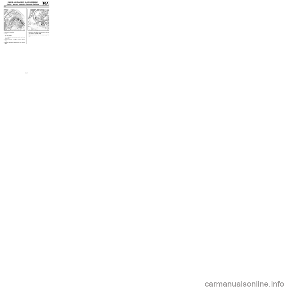
aRemove the fuses (20) .
aUnclip:
-the fuse holders,
-the engine compartment connection unit relay
plates (21) .
aRemove the earth nut (22) on the front left-hand
wing.
aMove the earth wiring away from the front left-hand
wing.aRemove the clip (23) on the coolant pump inlet pipe
hose using the tool (Mot. 1448).
aDisconnect the hose from the coolant pump inlet
pipe.
121435121431
Page 99 of 652
10A-93
ENGINE AND CYLINDER BLOCK ASSEMBLY
Engine - gearbox assembly: Removal - Refitting
K9K
10A
II - FINAL OPERATION
aRemove the.
aLubricate the seals using recommended air condi-
tioning oil to make fitting easier.
aRefit:
-the connecting pipes to the compressor,
-the connecting pipe union bolts on the compressor,
-the bolt for the connecting pipe mounting on the
compressor.
aConnect:
-the pressostat connector,
-the hose to the coolant pump inlet pipe using the
tool (Mot. 1448).
aFit:
-the hose clip on the coolant pump inlet pipe using
the tool (Mot. 1448),
-the earth on the front left-hand wing.
aRefit the earth nut on the front left-hand wing.
aClip:
-the engine compartment connection unit relay
plates,
-the fuse holders.
aRefit the fuses.
aConnect the preheating unit connector.
aRefit the earth nut on the front left-hand side mem-
ber.
aFit the engine compartment connection unit.
aRefit the engine compartment connection unit
mountings on the body.
aConnect the black connector.
aClip on the black connector.
aRefit:
-the engine compartment connection unit cover,
-a new clip on the battery mounting to hold the elec-
trical wiring.
aConnect the wiring connectors to the fan assembly.aClip the fan assembly wiring.
aRemove the blanking plugs.
aConnect the high pressure pump inlet pipe.
aClip on the fuel supply pipe.
aConnect the high pressure pump return pipe.
aClip on the fuel return pipe.
aRemove the blanking plugs on the clutch hydraulic
control and on the control pipe.
aConnect the clutch hydraulic control to the gearbox.
aClip:
-the clutch control hydraulic pipe on the gearbox,
-the gearbox controls on the cable sleeve stops,
-the gearbox controls on the gear selectors.
aConnect:
-the hoses to the heater radiator,
-the top hose to the water chamber.
aFit:
-the hose clips on the heater radiator using the tool
(Mot. 1448),
-the clip for the top hose on the water chamber us-
ing the tool (Mot. 1448).
aRefit:
-the front section of the intermediate pipe (see 19B,
Exhaust, Intermediate pipe: Removal - Refit-
ting, page 19B-28) ,
-the front right-hand wheel driveshaft (see Front
right-hand driveshaft: Removal - Refitting)
(29A, Driveshafts),
-the front left-hand wheel driveshaft (see Front left-
hand driveshaft: Removal - Refitting) (29A,
Driveshafts),
-the radiator mounting cross member (see Radiator
mounting cross member: Removal - Refitting)
(41A, Front lower structure),
-the front axle subframe (see Front axle subframe:
Removal - Refitting) (31A, Front axle compo-
nents),
-the engine tie-bar (see 19D, Engine mounting,
Lower engine tie-bar: Removal - Refitting, page
19D-18) . WARNING
To prevent any leaks, check that the seal and the
surface of the pipe are in good condition. The
seal and the surface must be clean and scratch
free.
Page 106 of 652
10A-100
ENGINE AND CYLINDER BLOCK ASSEMBLY
Engine - gearbox assembly: Removal - Refitting
K4M
10A
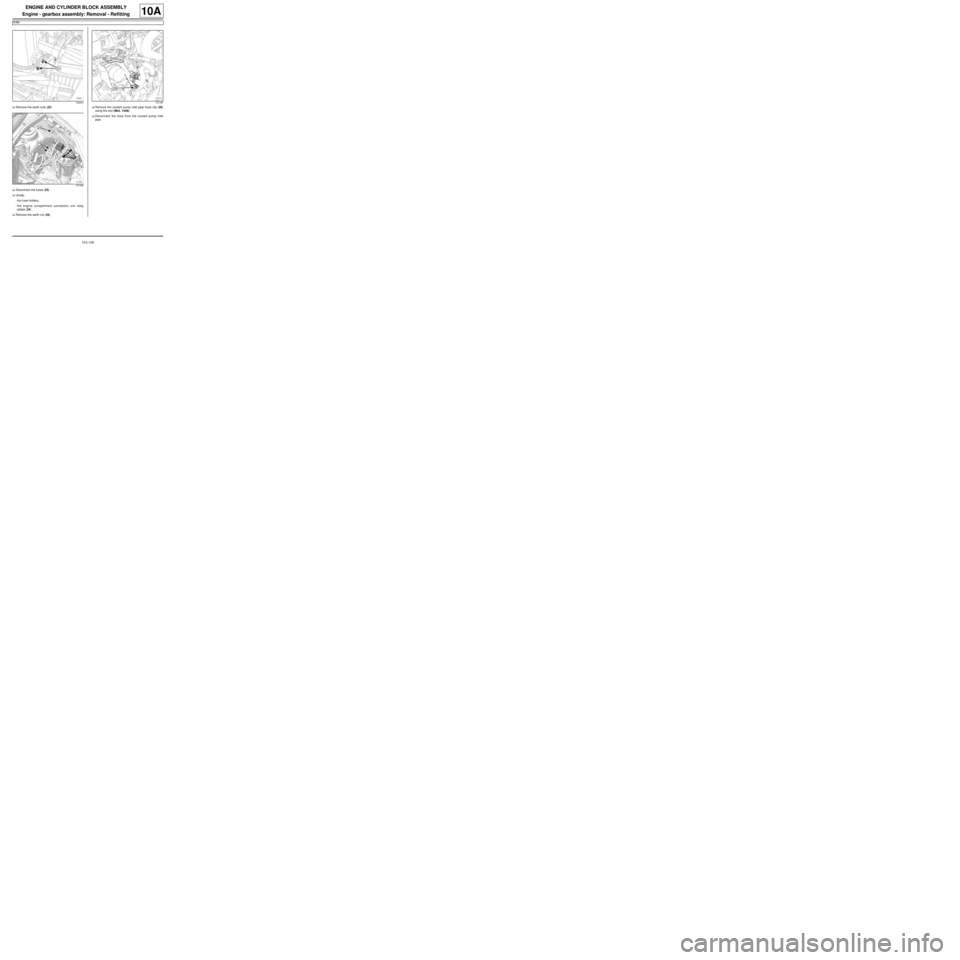
aRemove the earth nuts (22) .
aDisconnect the fuses (23) .
aUnclip:
-the fuse-holders,
-the engine compartment connection unit relay
plates (24) .
aRemove the earth nut (25) .aRemove the coolant pump inlet pipe hose clip (26)
using the tool (Mot. 1448).
aDisconnect the hose from the coolant pump inlet
pipe.
132347
121435131781